SM9209
SPECIFICATIONS AND PARTS ARE SUBJECT TO CHANGE FOR IMPROVEMENT
DVD DIGITAL THEATRE SYSTEM
SERVICE MANUAL
2002
November
Digital Media Division
HTDK160
ST
AN
DB
Y
DV
D
TU
NE
R
AU
X
2
5
8
0
SL
EE
P
RE
PE
AT
A-
B
N/P
ME
NU
/P
B
C
SL
OW
/M
EM
OR
Y
Zo
om
EQ
La
ng
ua
ge
AU
DI
O
Go
To
Su
bT
itle
AN
GL
E
Re
tur
n
DI
SP
LA
Y
MU
TE
SE
LE
CT
AD
J/V
OL
SE
TU
P
TIT
LE
PL
AY
/PA
US
E
OP
EN
/C
LO
SE
PR
OG
LIS
TE
NI
NG
EN
T
PO
WE
R
RE
MO
TE
CO
NT
RO
LL
ER
RB
-HT
DK
16
0
STANDBY

ENGLISH
SAFETY PRECAUTIONS
WARNING: The following precautions must be observed.
ALL PRODUCTS
Before any service is performed on the chassis an
isolation transformer should be inserted between the
power line and the product.
1. When replacing the chassis in the cabinet, ensure
all the protective devices are put back in place.
2. When service is required, observe the original
lead dressing. Extra precaution should be taken to
ensure correct lead dressing in any high voltage
circuitry area.
3. Many electrical
and
mechanical parts in
HITACHI products have special safety related
characteristics. These characteristics are often not
evident from visual inspection, nor can the
protection afforded by them necessarily be
obtained by using replacement components rated
for higher voltage, wattage, etc. Replacement
parts
which
have
these
special
safety
characteristics are identified by marking with a
! on the schematics and the replacement parts
list.
The use of a substitute replacement component
that does not have the same safety characteristics
as the HITACHI recommended replacement one,
shown in the parts list, may create electrical
shock, fire, X-radiation, or other hazards.
4. Always replace original spacers and maintain lead
lengths. Furthermore, where a short circuit has
occurred, replace those components that indicate
evidence of overheating.
5. Insulation resistance should not be less than 2M
ohms at 500V DC between the main poles and
any accessible metal parts.
6. No flashover or breakdown should occur during
the dielectric strength test, applying 3kV AC or
4.25kV DC for two seconds between the main
poles and accessible metal parts.
7. Before returning a serviced product to the
customer, the service technician must thoroughly
test the unit to be certain that it is completely safe
to operate without danger of electrical shock. The
service technician must make sure that no
protective device built into the instrument by the
manufacturer
has
become
defective,
or
inadvertently damaged during servicing.
CE MARK
1. HITACHI products may contain the CE mark on
the rating plate indicating that the product
contains parts that have been specifically
approved
to
provide
electromagnetic
compatibility to designated levels.
2. When replacing any part in this product, please
use only the correct part itemised in the parts list
to ensure this standard is maintained, and take
care to replace lead dressing to its original state,
as this can have a bearing on the electromagnetic
radiation/immunity.
PICTURE TUBE
1. The line output stage can develop voltages in
excess of 25kV; if the E.H.T. cap is required to be
removed, discharge the anode to chassis via a
high value resistor, prior to its removal from the
picture tube.
2. High voltage should always be kept at the rated
value of the chassis and no higher. Operating at
higher voltages may cause a failure of the picture
tube or high voltage supply, and also, under
certain circumstances could produce X-radiation
levels moderately in excess of design levels. The
high voltage must not, under any circumstances,
exceed 29kV on the chassis (except for projection
Televisions).
3. The primary source of X-radiation in the product
is the picture tube. The picture tube utilised for
the above mentioned function in this chassis is
specially constructed to limit X-radiation. For
continued X-radiation protection, replace tube
with the same type as the original HITACHI
approved type
4. Keep the picture tube away from the body while
handling. Do not install, remove, or handle the
picture tube in any manner unless shatterproof
goggles are worn. People not so equipped should
be kept away while picture tubes are handled
LASERS
If the product contains a laser avoid direct exposure to
the beam when the cover is open or when interlocks are
defeated or have failed.

CONTENTS
1 GENERAL INFORMATION ............................................... E1-1
1-1 SPECIFICATIONS ....................................................... E1-1
1-2 CONTROLLING VERSION OF FIRMWARE ............... E1-2
1-3 REPAIR INSTRUCTIONS ............................................ E1-3
2 EXPLODED VIEW ................................................................ 2-1
2-1 MAIN UNIT ..................................................................... 2-1
2-2 SUBWOOFER ................................................................ 2-2
3 REPLACEMENT PARTS LIST ............................................. 3-1
3-1 MAIN UNIT SECTION .................................................... 3-1
3-1-1 MECHANICAL PARTS LIST ..................................... 3-1
3-1-2 ELECTRICAL PARTS LIST ...................................... 3-2
TUNER ........................................................................... 3-2
SCART ........................................................................... 3-3
KEY PANEL .................................................................... 3-4
POWER .......................................................................... 3-5
MAIN ............................................................................... 3-6
3-2 SUBWOOFER SECTION ............................................... 3-9
3-2-1 MECHANICAL PARTS LIST ..................................... 3-9
3-2-2 ELECTRICAL PARTS LIST ................................... 3-10
AMP & JACK ................................................................ 3-10
POWER ........................................................................ 3-10
SCHEMATIC, CIRCUIT BOARD AND BLOCK DIAGRAMS ..... 1
1 MAIN UNIT SECTION ............................................................. 1
1-1 WIRING DIAGRAM ........................................................... 1
1-2 BLOCK DIAGRAM ............................................................ 2
1-3 SCHEMATIC DIAGRAMS ................................................. 3
TUNER ................................................................................. 3
SCART ................................................................................. 4
KEY PANEL .......................................................................... 5
POWER ............................................................................... 6
MAIN .................................................................................... 7
1-4 IC BLOCK DIAGRAMS ....................................................11
1-5 CIRCUIT BOARD DIAGRAMS ........................................ 16
TUNER ............................................................................... 16
SCART ............................................................................... 18
KEY PANEL ........................................................................ 19
POWER .............................................................................. 20
MAIN .................................................................................. 21
2 SUBWOOFER SECTION .......................................................23
2-1 WIRING DIAGRAM ......................................................... 23
2-2 BLOCK DIAGRAM .......................................................... 24
2-3 SCHEMATIC DIAGRAMS ............................................... 25
AMP & JACK ...................................................................... 25
POWER .............................................................................. 26
2-4 CIRCUIT BOARD DIAGRAMS ........................................ 27
AMP & JACK ...................................................................... 27
POWER .............................................................................. 28

E1 - 1
DVD Player
Pickup Semiconductor laser, Wavelength 650 mm
Signal system
NTSC / PAL
Video signal horizontal resolution 480 lines (DVD)
Video signal-to-noise ratio 50 dB (DVD)
Audio signal-to-noise ratio 60 dB
Total harmonic distortion 0.05%
Dynamic range DVD : 80 dB ; CD: 80 dB
FM Tuner
System PLL quartz-locked digital synthesizer system
Tuning range 87.50 ~ 108.00 MHz (50 kHz step)
Antenna FM pigtail antenna
Antenna terminals 75 ohms, unbalanced
Intermediate frequency 10.7 MHz
AM Tuner
System PLL quartz-locked digital synthesizer system
Tuning range 522~1620 kHz (9 kHz interval)
Antenna AM Loop antenna
Video outputs
CVBS Video 1 Vp-p 75 ohms
S-video Y: 1 Vp-p 75 ohms
C: PAL 0.3 Vp-p 75 ohms / NTSC 0.286 Vp-p 75 ohms
Scart out 1 Vp-p 75 ohms
Optical & Coaxial out 1 Vp-p 75 ohms
Audio line outputs
Audio L/R 1 Vrms, 1k ohms
Subwoofer 1.2Vrms maximum (adjustable), 1k ohms
Audio power outputs
Stereo mode 50 W + 50 W (8 ohms at 1 kHz, THD 10%)
Surround mode Front: 50 W + 50 W (8 ohms at 1 kHz, THD 10%)
Center: 50 W (8 ohms at 1 kHz, THD 10%)
Rear: 50 W + 50 W (8 ohms at 1 kHz, THD 10%)
Phones Headphones jack(stereo 3.54mm)
General (main unit)
Power requirements AC 220 - 240 V, 50 Hz
Power consumption 250 W
Dimensions W 435 x H 59 x D 345 mm
Weight 4.8 kg
Active Subwoofer
Output power : 100 W (4 ohms at 55Hz, THD 10%)
Speaker system : Bass reflex
Power requirements : AC 220 - 240 V, 50 Hz
Power consumption : 165 W
Speaker unit : 8 inches
Rated impedance : 4 ohms
Dimensions : W 200 x H 360 x D 345 mm
Weight : 9.8 kg
Front / Center / Rear speakers
Power: 50 W maximum
Speaker system: Bass reflex
Speaker unit: 3 inches,cone type: paper
Rated impedance: 8 ohms
Dimensions: W 90 x H 150 x D 110 mm
Weight: 0.64 kg (rear speaker)
0.82 kg (front , center speaker)
1-1 SPECIFICATIONS
MAIN UNIT
SPEAKERS
GENERAL INFORMATION
1
E1 - 2
1-2 CONTROLLING VERSION OF FIRMWARE
The firmware is regularly modified as required to improve the
performance.
Check to see whether the customer problem can be solved by
upgrading the firmware : If it can, do so.
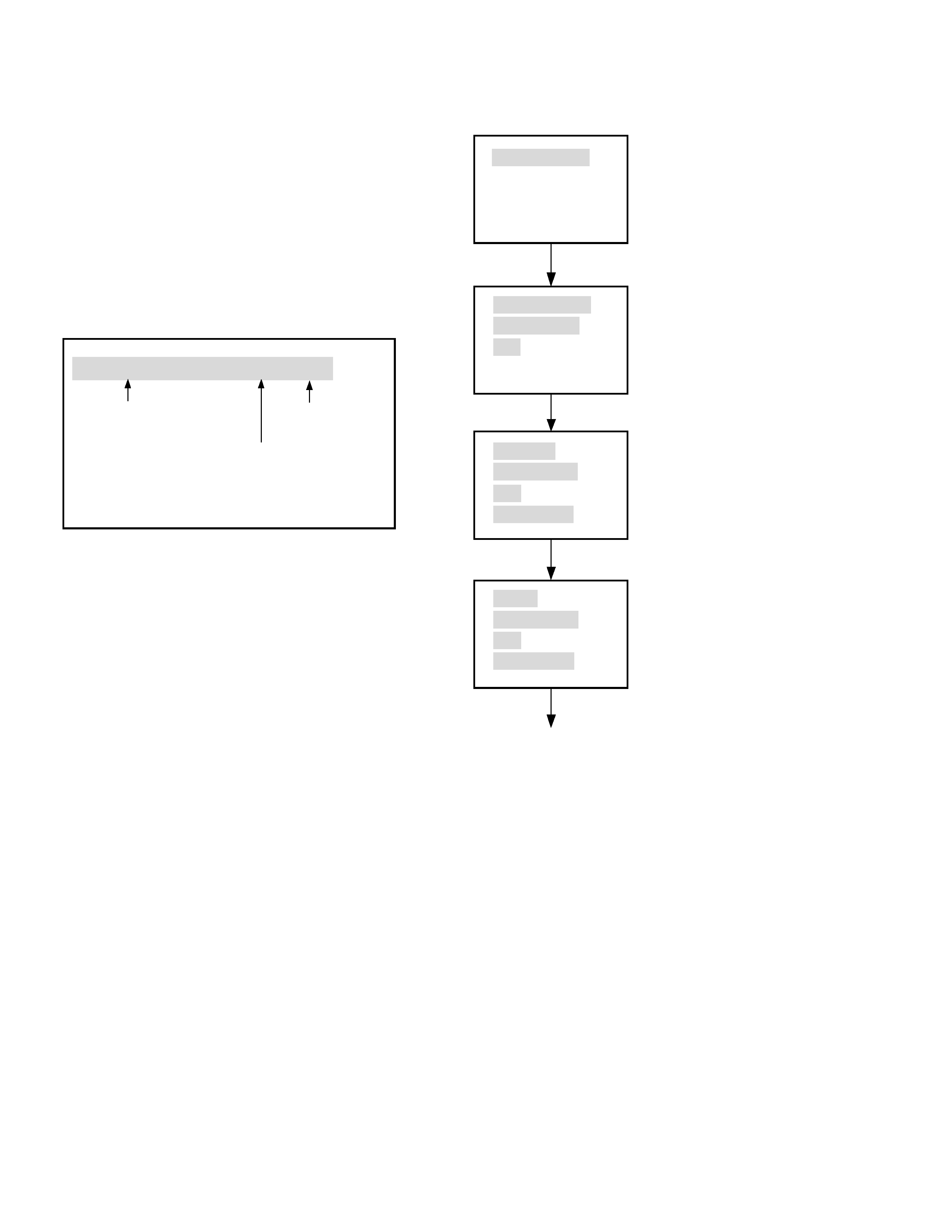
<Procedure for checking the version of firmware>
1) Open the tray with power on.
2) While holding down the "ADJ/VOL (+)" key on remote con
trol, press the "Zoom" key.
3) The version of firmware will appear at the top left of screen.
(The display will disappear in approx. 5 seconds.)
VER XXXX
1 ATUO
EUR
2 0
Version No.
Region Code
Tuner Area
<Procedure for rewriting firmware>
1) Turn power on.
2) Place the upgrade CD-R on tray, and press the"OPEN/
CLOSE" or "PLAY" key.
3) Messages will appear at the top left of screen in the order
shown below ("MP3 STOP" will appear in the display).
4) When rewrite of the firmware is complete, the system will
automatically turn off.
5) Unplug the power cord and then plug it in again.
6) Turn power on, and press the "OPEN/CLOSE" key while
"LOADING" is shown in the display to remove the upgrade
CD-R (if the CD-R is left in the tray, rewrite of the firmware
will restart).
7) Check the version of firmware.
Caution: Be sure not to unplug the power cord during the
rewrite operation.
Note:
If the firmware has been changed, etc., we will use Service
News, etc. to report on how to obtain new firmware data and
create an upgraded disc.
DISC LOADING
BANK30.ROM
READ START
015
WRITING
READ START
000
READ OVER
DONE
READ START
000
READ OVER
Power will automatically turn off.
* 1) 015 will be counted down to 000.
* 2) WRITING will flash.