SM0763
RAD-25NH4
RAD-40NH4
RAI -25NH4
RAI -40NH4
SERVICE MANUAL
TECHNICAL INFORMATION
INFORMATIONS TECHNIQUES
REFER TO THE FOUNDATION MANUAL AND
SERVICE MANUAL TC NO.0757EF, TC NO. 0758EF.
RÉFÉREZ-VOUS AU COMITÉ TECHNIQUE TC NO.0758EF,
TC NO.0757EF DE MANUEL DE BASE ET DE MANUEL
D'ENTRETIEN TECHNIQUE DE RÉPARATION.
ROOM AIR CONDITIONER
SPECIFICATIONS AND PARTS ARE SUBJECT TO CHANGE FOR IMPROVEMENT
LES SPECIFICATIONS ET PIECES DETACHEES PEUVENT CHANGER POUR ETRE AMELIOREES.
FOR SERVICE PERSONNEL ONLY
RESERVE AU PERSONNEL
SPECIFICATIONS
CARACTERISTIQUES GENERALES
NOTE:
This manual describes only points that differ from RAF-25, 50NH4,
RAD-25, 40QH4 / RAM-70, 80QH4 (TC No. 0757EF) and RAM-60QH4
(TC NO. 0758EF) for items not described in this manual.
REMARQUE:
Le présent manuel décrit uniquement les points qui diffèrent avec les
descriptions pour les modèles RAF-25, 50NH4, RAD-25, 40QH4 / RAM-70,
80QH4 (TC NO. 0757EF) et RAM-60QH4 (TC NO. 0758EF) à propos des
rubriques qui ne sont pas traitées dans ce manuel.
SPECIFICATIONS
CARACTERISTIQUES GENERALES
FEATURES
CARACTÉRISTIQUES
HOW TO USE
UTILISATION
INSTALLATION
INSTALLATION
CONSTRUCTION AND DIMENSIONAL DIAGRAM
DIMENSIONS DES UNITÉS
MAIN PARTS COMPONENT
PRINCIPAUX COMPOSANTS
WIRING DIAGRAM
SCHÉMAS ÉLECTRIQUES
WIRING DIAGRAM OF THE PRINTED WIRING BOARD
SCHÉMA ÉLECTRIQUE DU CIRCUIT IMPRIMÉ
BLOCK DIAGRAM
ORGANIGRAMME DE CONTROLE
BASIC MODE
MODE DE BASE
REFRIGERATING CYCLE DIAGRAM
SCHÉMA DU CYCLE DE RÉFRIGÉRATION
AUTO SWING FUNCTION
FONCTION BALAYAGE AUTOMATIQUE
DESCRIPTION OF MAIN CIRCUIT OPERATION
DESCRIPTION DES PRINCIPAUX CIRCUITS ÉLECTRIQUES
SERVICE CALL Q&A
MODE OPERATOIRE DE DEPANNAGE
TROUBLE SHOOTING WHEN THE TIMER LAMP BLINKS
DEPANNAGE LORSQUE LE TEMOIN DE MINUTERIE CLIGNOTE
PARTS LIST AND DIAGRAM
LISTE DES PIÉCES DE RECHANGE ET DIAGRAMME
CONTENTS
TABLE DES MATIERES
TYPE
TYPE
MODEL
MODÈLE
POWER SOURCE
PHASE/TENSION/FREQUENCE
TOTAL INPUT
PUISSANCE ABSORBEE TOTALE
(W)
TOTAL AMPERES
AMPERES TOTAUX
(A)
COOLING CAPACITY
REFRIGERATION CAPACITE
(kW)
HEATING CAPACITY
CHAUFFAGE CAPACITE
(kW)
W, L
DIMENSIONS
DIMENSIONS
(mm)
H, H
D, P
NET WEIGHT
POIDS NET
(kg)
DC INVERTER SYSTEM MULTI (FREE DUCT, CEILING CASSETTE)
SYSTÈME D'INVERSEUR DE C.C. MULTI (GAINE LIBRE, CASSETTE AU PLAFOND)
INDOOR UNIT
UNITÉ INTÉRIEURE
1ø, 230V, 50Hz
RAD-25NH4
RAI-25NH4
RAD-40NH4
RAI-40NH4
REFER TO THE SPECIFICATIONS PAGE ( 9 )
REPORTEZ-VOUS AUX SPECIFICATIONS DE LA PAGE ( 11 )
INDOOR UNIT
MAY 2004
Hitachi Home & Life Solutions, Inc.
750
235
400
14.0
580
285
580
20.0
9
38
46
76
86
91
92
97
107
115
150
154
156
182
190
208
RAI-25NH4
RAI-40NH4
RAD-25NH4
RAD-40NH4
PANEL:RAI-ECPM
PANNEAU:RAI-ECPM
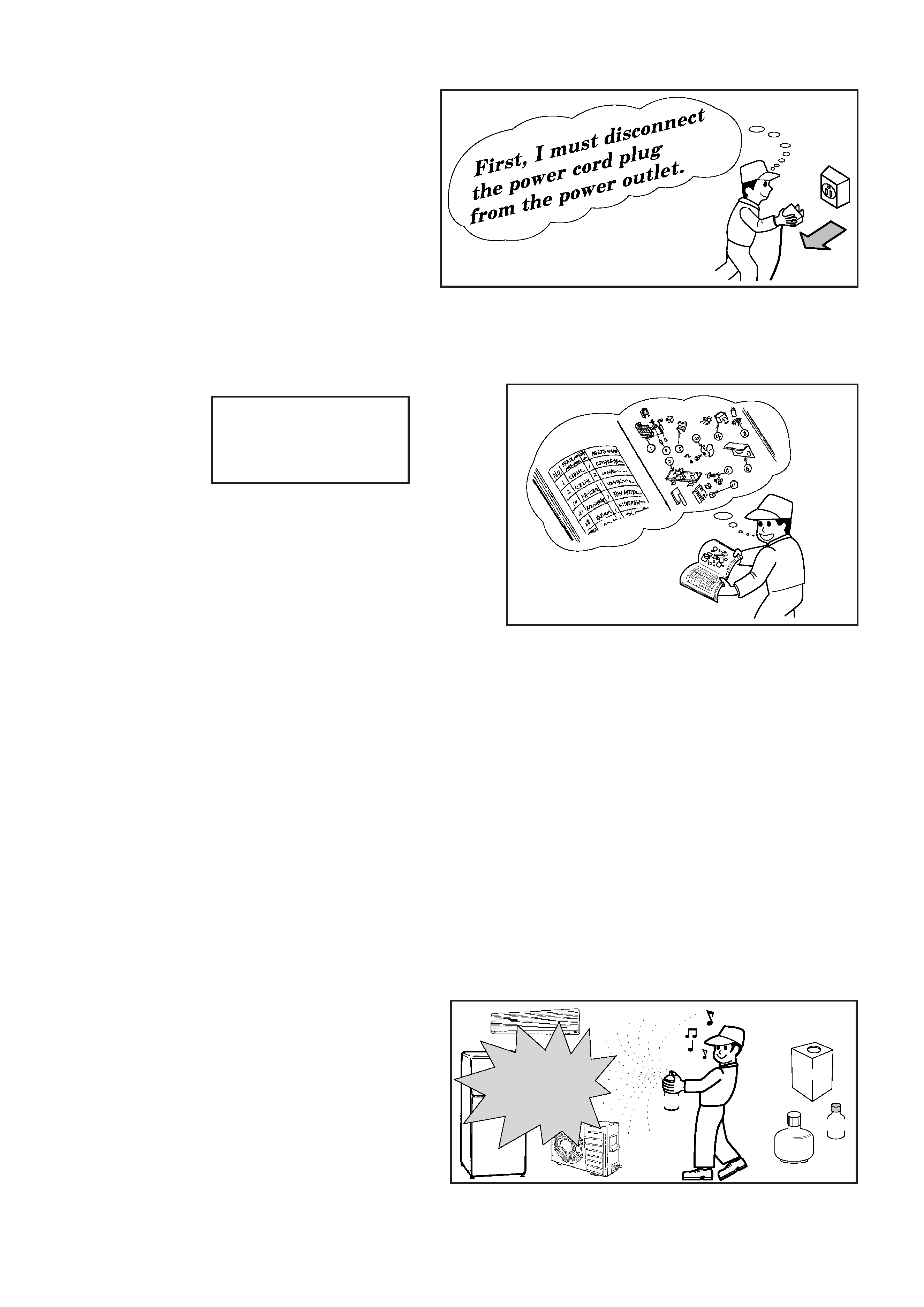
1. In order to disassemble and repair the
unit in question, be sure to disconnect the
power cord plug from the power outlet
before starting the work.
2. If it is necessary to replace any parts, they should be replaced with respective genuine parts for the unit,
and the replacement must be effected in correct manner according to the instructions in the Service
Manual of the unit.
3. After completion of repairs, the initial state should be
restored.
4. Lead wires should be connected and laid as in the
initial state.
5. Modification of the unit by the user himself should
absolutely be prohibited.
6. Tools and measuring instruments for use in repairs or inspection should be accurately calibrated in
advance.
7. In installing the unit having been repaired, be careful to prevent the occurrence of any accident such as
electrical shock, leak of current, or bodily injury due to the drop of any part.
8. To check the insulation of the unit, measure the insulation resistance between the power cord plug and
grounding terminal of the unit.
The insulation resistance should be 1M
9 or more as measured by a 500V DC megger.
9. The initial location of installation such as window, floor or the other should be checked for being safe
enough to support the repaired unit again.
If it is found not so strong and safe, the unit should be installed at the initial location after reinforced or
at a new location.
10. Any inflammable object must not be placed
about the location of installation.
11. Check the grounding to see whether it is
proper or not, and if it is found improper,
connect the grounding terminal to the earth.
Spray
gasoline
gasbombe
thinner
SAFETY DURING REPAIR WORK
If the contacts of electrical
parts are defective, replace
the electrical parts without
trying to repair them
1
2
3
4
5
2
WORKING STANDARDS FOR PREVENTING BREAKAGE OF SEMICONDUCTORS
1. Scope
The standards provide for items to be generally observed in carrying and handling semiconductors in
relative manufactures during maintenance and handling thereof. (They apply the same to handling of
abnormal goods such as rejected goods being returned.)
2. Object parts
(1) Micro computer
(2) Integrated circuits (I.C.)
(3) Field effective transistor (F.E.T.)
(4) P.C. boards or the like to which the parts mentioned in (1) and (2) of this paragraph are equipped.
3. Items to be observed in handling
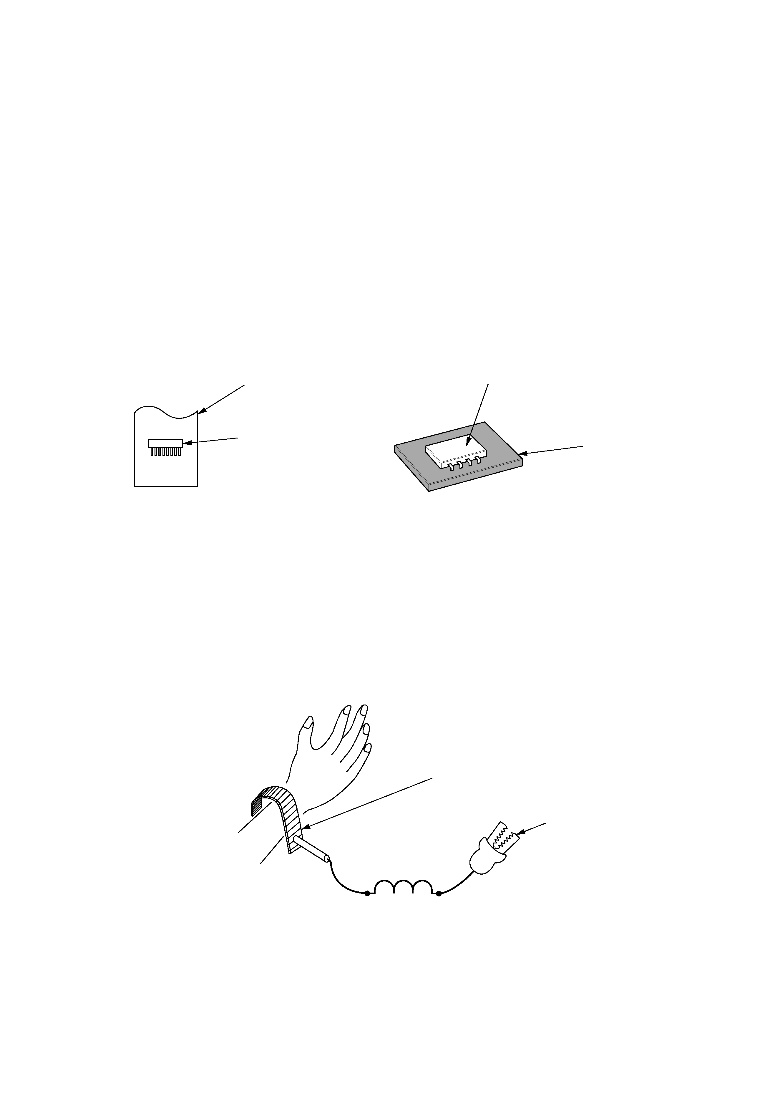
(1) Use a conductive container for carrying and storing of parts. (Even rejected goods should be handled in
the same way.)
(2) When any part is handled uncovered (in counting, packing and the like), the handling person must
always use himself as a body earth. (Make yourself a body earth by passing one M ohm earth
resistance through a ring or bracelet.)
(3) Be careful not to touch the parts with your clothing when you hold a part even if a body earth is
being taken.
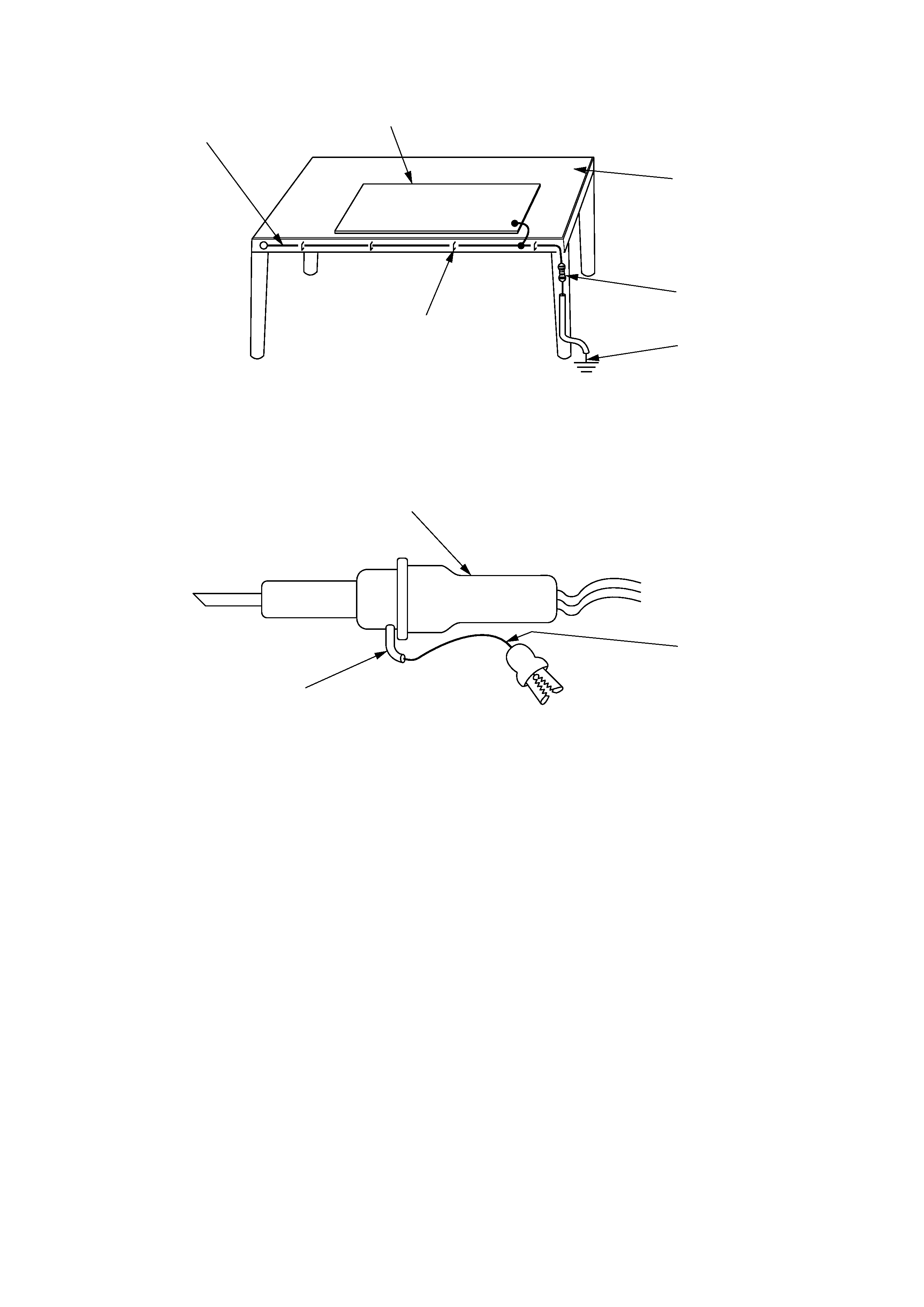
(4) Be sure to place a part on a metal plate with grounding.
(5) Be careful not to fail to turn off power when you repair the printed circuit board.
At the same time,
try to repair the printed circuit board on a grounded metal plate.
HIT
ACH
I IC4
01T
H1 ,
188
UV
Fig. 1 Conductive container
A conductive polyvinyl bag
IC
IC
Conductive sponge
Fig. 2 Body earth
Body earth (Elimik conductive band)
Clip for connection with
a grounding wire
1M
9
4
(6) Use a three wire type soldering iron including a grounding wire.
Fig.4 Grounding a solder iron
Use a high insulation mode (100V, 10M
9 or higher) when ordinary iron is to be used.
(7) In checking circuits for maintenance, inspection, or some others, be careful not to have the test probes
of the measuring instrument shortcircuit a load circuit or the like.
Bare copper wire (for body earth)
Metal plate (of Al. stainless steel, etc.)
Working table
Resistor 1M
9(1/2W)
Earth wirte
Staple
Fig.3 Grounding of the working table
soldering iron
Grounding wire
Screw stop at the screwed
part using a rag plate

6
1. In quiet operation or stopping the running, its heard slight flowing noise of refrigerant
in
the
refrigerating
cycle
occasionally,
but
this
noise
is
not
abnormal
for
the
operation.
2. When it thunders near by, it is recommend to stop the operation and to disconnect
the power cord plug from the power outlet for safety.
3. The room air conditioner dose not start automaticaly after recovery of the electric
power failure for preventing fuse blowing.
Re-press START / STOP button after 3
minutes from when unit stopped.
4. If the room air conditioner is stopped by adjusting thermostat, or missoperation, and
re-start in a moment, there is occasion that the cooling and heating operation does
not start for 3 minutes, it is not abnormal and this is the result of the operation of
IC delay circuit.
This IC delay circuit ensures that there is no danger of blowing
fuse or damaging parts even if operation is restarted accidentally.
5. This room air conditioner should not be used at the cooling operation when the
outside temperature is below 10°C (50°F).
6. This room air conditioner (the reverse cycle) should not be used when the outside
temperature is below 15°C (5°F).
If the reverse cycle is used under this condition, the outside heat exchanger is
frosted and efficiency falls.
7. When the outside heat exchanger is frosted, the front is melted by operating the hot
gas system, it is not trouble that at this time fan stops and the vapour may rise
from the outside heat exchanger.
8. With this model, lead-free solder is used for P.W.B.. Since the melting point of this
solder is higher than conventional solders, the soldering iron may become too hot
when replacing component on P.W.B., and the component could break. Therefore,
replace P.W.B. for repair except in unavoidable circumstances.
CAUTION