SPECIFICATIONS AND PARTS ARE SUBJECT TO CHANGE FOR IMPROVEMENT.
Plasma Display
August 2004 Digital Media Division
YK
No.00
9E-1
SERVICE MANUAL
Be sure to read this manual before servicing. To assure safety from fire, electric shock, injury, harmful radiation
and materials, various measures
have been provided for in this HITACHI Plasma displayservice manual.
Be sure to read
all cautionary items described in the manual to maintain safety before servicing.
Contents
1. Since
the Panel Module and front Filter are made of glass, handle a broken Module and/or Filter with
sufficient care, in order not to be injured.
2. Rep
air work should not be started until after the Panel Module and the AC/DC Power supply have cooled
sufficiently.
3. Special care sh
ould be exercised in the proximity of the display area in order not to damage its surface.
4. The Panel Module sh
ould not be touched with bare hands, as this will protect its surface from stains.
5. It is recommended to use clean soft gloves during the rep
air work in order to protect not only the display
area of the Panel Module but also
the technician.
6. The Chip Tube of
the Panel Module (located in the upper left corner of the back of the glass panel)
is very fragile; as well, the flat cables connecting the Panel to the drive circuit PWBs are very weak. Take
care not to damage these, otherwise, the panel will never light again.
Service Warning
Caution
1. Features ----------------------------------------------- 3
2. Specifications----------------------------------------- 4
3. Component Names --------------------------------- 5
4. Service point ------------------------------------------ 6
5.
Service Modes -------------------------------------7
6. Troubleshooting ------------------------------------ 3
4
7.
Block Diagram ------------------------------------ 37
CH 4
CMP420V1 / CMP420V2
42EDT41
(PW1A)
8. Connector Diagram ....................................... 40
9. Wiring Diagram ............................................. 41
10. Basic Circuit Diagram .................................. 43
11. Printed Wiring Board Diagram ..................... 47
12. Disassembly Diagram .................................. 50
13. Replacement Parts List ................................ 51
14. DC Voltages ................................................. 53
Version 009E-1.4
CH 1
CH 2, CH 3
2
CMP420V1/CMP420V2/42EDT41 (PW1A)
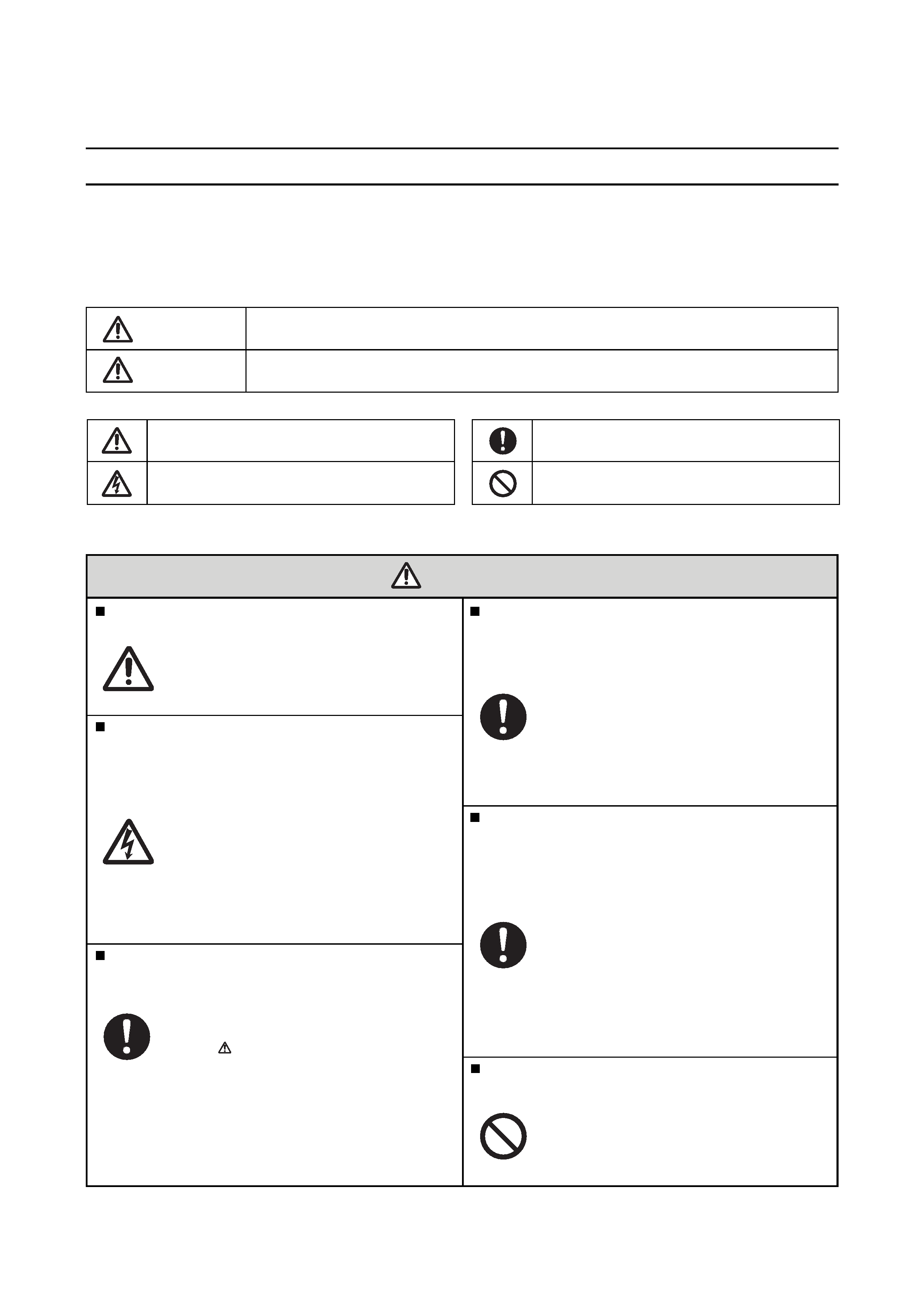
CAUTION FOR SAFETY
Please read this page before
making repairs to the monitor.
This page explain
s certain safety items found in this manual which are intended to ensure the
safety of the technician and to prevent accidents during any repair work.
Warning
This symbol means "
Personnel Electrical Safety Hazard"
Caution
This symbol means "
Equipment Operational Hazard"
This symbol means "CAUTION"
This symbol means "POSSIB
ILITY OF
ELECTRIC SHOCK"
This symbol means "
DO IT!"
This symbol means "DON
'T DO IT!"
S
pecial Instructions
This indicates cabinet, chassis or parts
which
require special attention.
Please follow
any notes as well as all safety
precautions.
Prevent
electrical shock
Please use care and caution when
servicing this product. High voltages
exist in the set which can cause injury
or death.
Please disconnect
the AC power
during repair to prevent serious shock
or death.
Use
only recommended components.
Please use t
he same characteristic compo-
nent
s, which is same as previous for your
safety
. To ensure reliability, specially marked
Keep the same wiring dress for boards.
This monitor uses insulated spacers
which are intended to isolate metal
parts from electrical components.
Internal
wiring is isolated from components by
using clamps, retainers, etc., so please return
to original condition for prevention of electrical
shock or fire.
S
afety check should be done after finished.
Every part (removed screws, component
and wiring) should be returned to previous
condition.
Check around
the repaired area for
any damage by mistake. Measure the
insulated impedance
of AC by ohm meter.
Confirm
that the value of impedance
is
greater than 4M ohm.
It is
possible for electric shock or fire to
occur if the value is less than 4M ohm.
Repair to the HDCP circuit is limited.
Never remove the shield case, which is
assembled to code
with the HDCP circuit
WARNING
parts ( ) should be OEM when replaced.
These parts are also safety related, so
electrical shock and/or fire could result
from using generic parts.
3
CMP420V1/CMP420V2/42EDT41 (PW1A)
PRECAUTIONS
How to clean the plasma
panel screen (front glass) of the monitor
Before cleaning the monitor, turn off the monitor and disconnect the power plug from the power outlet.
To prevent scratching or damaging the plasma screen face, do not
wipe the surface with sharp or hard
objects. Clean the screen with a soft cloth moistened with warm water and dry with a soft cloth. If it is not
clean enough, then use a cloth with glass cleaner. Do not use any harsh or abrasive chemicals.
How to clean the cabinet of the monitor
Use a soft cloth to clean the cabinet and control panel of the monitor. When excessively soiled dilute a neutral
detergent in water, wet and wring out the soft cloth and afterward wipe with a dry soft cloth.
Never use acid/alkaline detergent, alcoholic detergent, abrasive cleaner, powder soap, OA cleaner, car wax,
etc. because they
could cause discoloration, scratches or cracks.
1. Features
Large-screen, high-definition plasma display panel
The
42-inch color plasma display panel, with a resolution of 852 (H) x 480(V) pixels, creates a high-definition, large-
screen (aspect ratio : 16:9) and low-profile flat display. Free from electromagnetic interferences from geomagnetic
sources and ambient power lines, the panel produces
medium-quality images free from any color misconvergence
or corner focus distortion.
High Performance Digital Processor
A wide range of personal computer signals can be handled, from 640 x 400, 640 x 480 VGA to 1600 x 1200 UXGA.
(RGB analog input)
Easy-to-use remote control and on
-screen-display system (OSD)
The remote control included eases the setting
of display controls. Furthermore, the on-screen-display (OSD),
displays the
input status control settings in an easy-to-view fashion.
Power saving system
The International ENERGY STAR power saver feature saves power consumption automatically when input sig-
nals are not available.
When connected to a VESA DPMS-compliant PC, the monitor cuts its power consumption while it is idle.
TruBass
TruBass, SRS and ( ) symbol are trademarks of SRS Labs,Inc.
TruBass technology is incorporated under license from SRS Labs, Inc.
[AV MONITOR model] CMP420V1, CMP420V2
[TELEVISION model] 42EDT41
- One mini D-sub terminal and one DVI-D terminal for RGB input.
(The D-sub terminal can also receive component RGB - selectable via customer OSD.)
- One composite/S-video input terminal and two component video input terminals, added with VIDEO board.
(One of the component inputs has the capability to select RGB via customer OSD.)
- One SCART terminal for European standard, added with VIDEO board.
(It operates as composite/S-video input and RGB input terminal, or composite video output terminal.
-One composite video output terminal as a monitoring output, added with VIDEO board.
-Simple type remote (CP-RD4)
- Various input/output terminals, added with VIDEO board. (same features as above mentioned AV MONITOR)
- Tuner input added with VIDEO board
- Complex type remote (CLU-W900)
4
CMP420V1/CMP420V2/42EDT41 (PW1A)
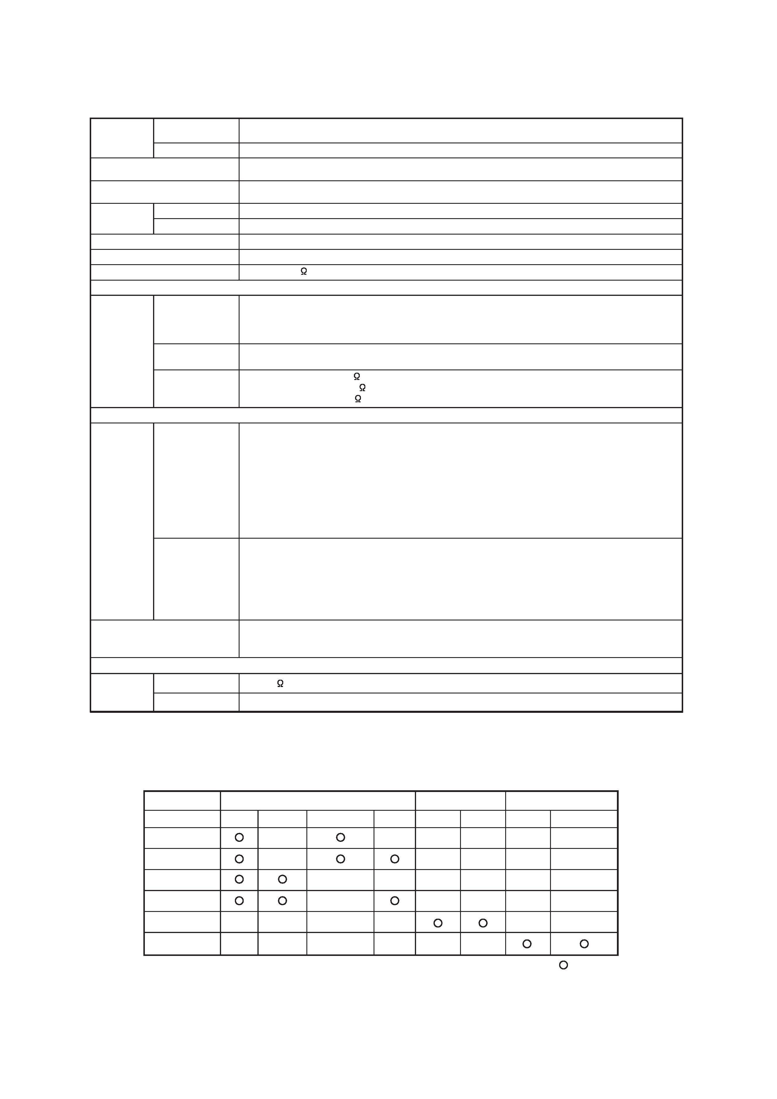
2. Specifications
Panel
Display
dimensions
Approx. 42 inches (920 (H) x 518 (V) mm, diagonal 1059mm)
Resolution
852 (H) x 480 (V) pixels
Net dimensions
(excluding Speakers/Stand)
1030 (W) x 636 (H) x 91 (D) mm
Net weight
(excluding Speakers/Stand)
CMP420V1/V2:33.2kg 42EDT41:34.2kg
Ambient
conditions
Temperature
Relative humidity
Operating : 20% to 80%, Storage : 20% to 90% (non-condensing)
Power supply
AC100 - 240V, 50/60Hz
Power consumption/at standby
310W / <3W
Audio output
(RGB input)
Input signals
Input terminals
RGB1 DVI input terminal (DVI-D)
RGB1 audio input terminal (3.5mm Stereo Mini Jack)
RGB2 analog RGB input terminal (D-sub 15-pin)
RGB2 audio input terminal (3.5mm Stereo Mini Jack)
Video signals
0.7 V/1.0 Vp-p, analog RGB (Recommended Signal)
480i, 576i, 480p, 576p, 1080i/50, 1080i/60, 720p/60
Sync signals
H/V separate, TTL level [2K ]
H/V composite, TTL level [2K ]
Sync on green, 0.3 Vp-p [75 ]
(Video input)
(RF input)
Input signals
Input signals
Input terminals
Input terminals
RF Video System
AV1: composite video input terminal (RCA)
AV1: Y PB PR video input terminal (RCA)
AV1: L/R audio input terminal (RCA)
AV2: composite video input terminal (RCA)
AV2: Y/G PB/B PR/R video input terminal (RCA)
AV2: L/R audio input terminal (RCA)
AV3: composite video input terminal (RCA)
AV3: S video input terminal (RCA)
AV3: L/R audio input terminal (RCA)
AV4: composite video / S video / RGB / L/R audio input terminal (Scart)
Video signals
AV1: NTSC-M, PAL-M, PAL-N
AV1: 480i, 576i, 480p, 576p, 1080i/50, 1080i/60, 720p/60
AV2: NTSC-M, PAL-M, PAL-N
AV2: 480i, 576i, 480p, 576p, 1080i/50, 1080i/60, 720p/60, RGB
AV3: NTSC-M, PAL-M, PAL-N
AV4: NTSC-M, PAL-M, PAL-N
NTSC-M
AV4: RGB
Video output Signal
OUTPUT (MONITOR): composite video monitor-output terminal (RCA)
OUTPUT (MONITOR): L/R audio monitor- output terminal (RCA)
AV4: composite video / L/R audio monitor-output terminal (SCART)
Operating : 5
to 35
, Storage : -15
to 60
12W + 12W (6
)
ANT : 75
unbalanced
Applicable video signals for each input terminal
Terminal
RCA/SCART
DVI
D-sub
Signal
CVBS
S-video
Component
RGB
PC
STB
RGB
Component
AV1
AV2
AV3
AV4
RGB1
RGB2
(
:Available)
5
CMP420V1/CMP420V2/42EDT41 (PW1A)
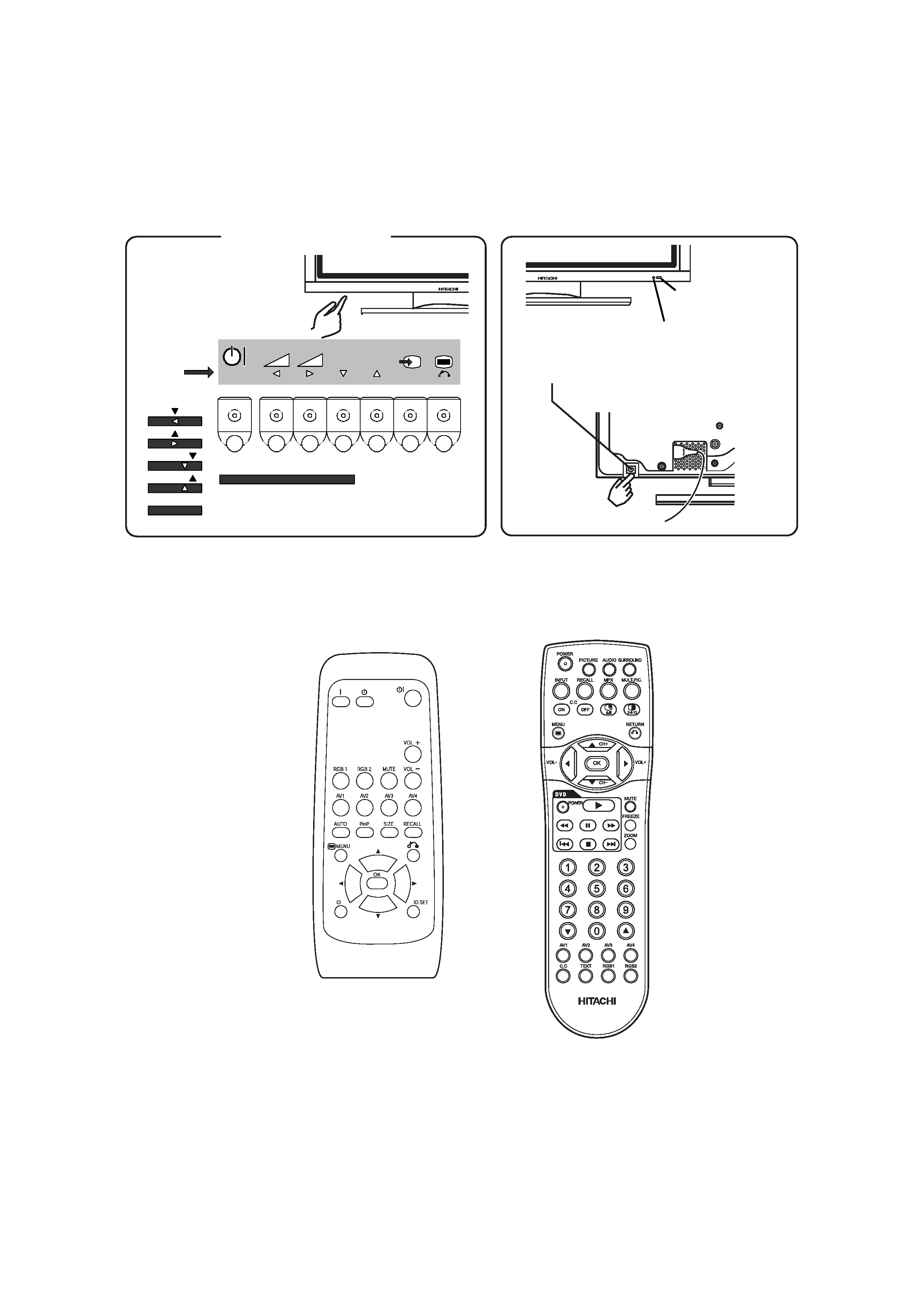
3. Component names
Remote-control
receiver
· Adjustment buttons are located
on the bottom.
· The back cover is provided with
indications to distinguish the
adjustment buttons.
Control panel
Main power switch
· The main power switch is located at the back, on the
lower surface.
Indicating lamp
for
CMP420V1
CMP420V2
for
42EDT41
[Remote control]
[Main unit]
NOTE:
1st number indicates normal button operation
2nd number indicates function during MENU
Rear Label
7
6
5
4
3
2
1
-
+
OK
2. VOL
2. ADJ
1. SUB POWER
3. VOL
3. ADJ
4. PROGRAM
4. SELECT
5. PROGRAM
5. SELECT
6. INPUT SELECT
6. OK
7. MENU