SPECIFICATIONS AND PARTS ARE SUBJECT TO CHANGE FOR IMPROVEMENT.
Multimedia LCD Projector
October 2005 Digital Media Division
SM0559
PJ-TX200
E (C11H2)
SERVICE MANUAL
Be sure to read this manual before servicing. To assure safety from fire, electric shock, injury, harmful
radiation and materials, various measures are provided in this Hitachi Multimedia LCD Projector. Be
sure to read cautionary items described in the manual to maintain safety before servicing.
Caution
1. When replac
ing the lamp, avoid burns to your fingers as the lamp becomes very hot.
2. Never touch the lamp bulb with a finger or anything else. Never drop it or give it a shock. They may
cause bursting of the bulb.
3. This projector is provided with a high voltage circuit for the lamp. Do not touch the electric
al parts of
the power unit when turning on the projector.
4. Do not touch the exhaust fan during operation.
5. The LCD module assembly is likely to be damaged. If replacing the LCD LENS/PRISM assembly,
do not hold the FPC of the LCD module assembly.
6. Use the cables which are included with the projector or specified.
Service Warning
Warning
The technical information and parts shown in this
manual are not to be used for: the development,
design, production, storage or use of nuclear, chemical,
biological or missile weapons or other weapons of
mass destruction; or military purposes; or purposes that
endanger global safety and peace. Moreover, do not
sell, give, or export these items, or grant permission for
use to parties with such objectives. Forward all inquiries
to Hitachi Ltd.
1. Features ----------------------------------------------- 2
2. Specifications----------------------------------------- 2
3. Names of each part --------------------------------- 3
4. Adjustment -------------------------------------------- 6
5. Troubleshooting ------------------------------------ 13
6. Service points -------------------------------------- 18
7. Wiring diagram ------------------------------------- 30
8. Disassembly diagram----------------------------- 35
9. Replacement parts list---------------------------- 40
10.RS-232C commands ----------------------------- 41
11. Block diagram -------------------------------------- 51
12.Connector connection diagram ---------------- 52
13.Basic circuit diagram------------------------------ 53
Contents
2
PJ-TX200(C11H2)
1. Features
· Super focus ED (Extra-low dispersion) lenses are adopted for the highest possible image quality.
· 720P wide LCD panels realize faithful reproduction of high-definition images.
· Motorized iris control is provided for realizing film-like images with blacker black.
· 1.6x zoom lens and the optical lens shift allow flexible installation and viewing position.
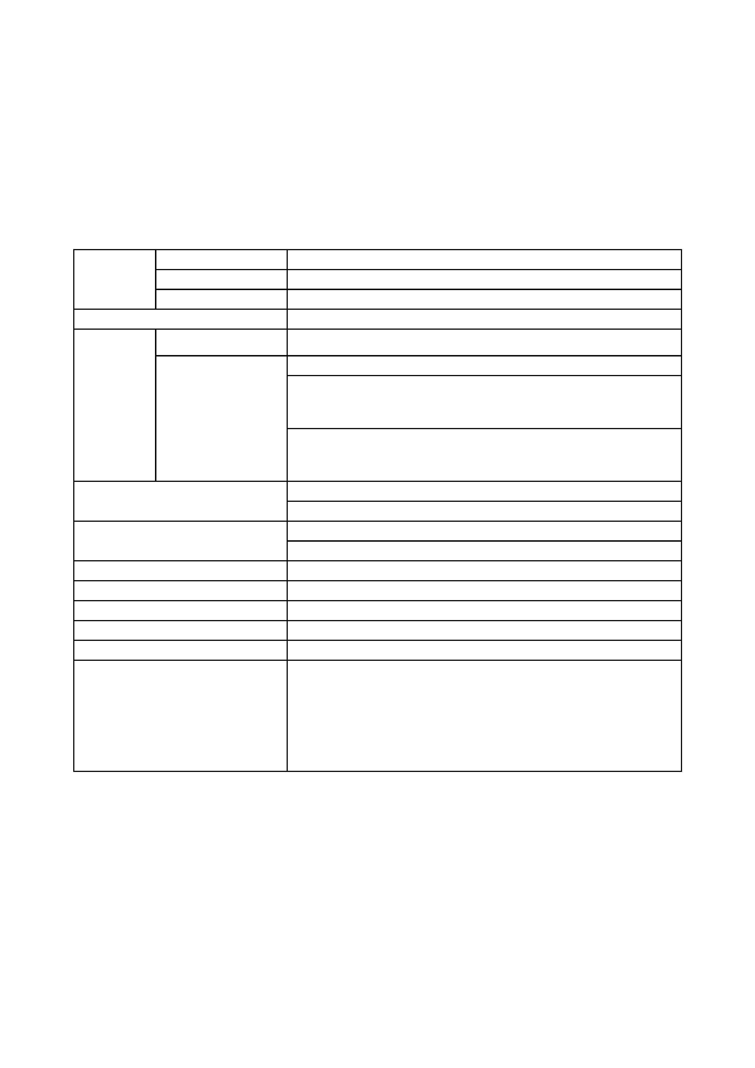
2. Specifications
Liquid crystal
panel
Drive system
TFT active matrix
Panel size
1.8cm(0.7 type)
Number of pixels
1280 (H) x 720 (V)
Lamp
150W UHB
Video Input
System
NTSC,PAL(BGDHI),SECAM,PAL-M,PAL-N,NTSC4.43,PAL60
Level
Composite 1.0±0.1Vp-p(75termination)
S-Video Y : 1.0±0.1Vp-p(75termination)
C : 0.286±0.1Vp-p(NTSC burst signal,75termination)
0.3±0.1Vp-p(PAL/SECAM burst signal,75termination)
Component Y : 1.0±0.1Vp-p(75termination)
CB/PB : 0.7±0.1Vp-p(75termination)
CR/PR : 0.7±0.1Vp-p(75termination)
RGB analog input
Video signal: 0.7V p-p (75termination)
Sync. signal: TTL level
HDMI digital input
Type: T.M.D.S
Signal level: DC: 3.3V±5%, AC: 0.15 - 1.56Vp-p
Power supply
AC100~120V / 2.4A , AC220~240V / 1.3A
Power consumption
220W
Dimensions
340(W) × 113(H) × 299(D) mm (No including protruding parts)
Weight
4.7kg(10.4lbs)
Temperature
Operation : 5~35°C Storage : -20~60°C
Accessories
Power cord
PJ-TX200W x 3 (US, UK, Europe)
PJ-TX200E x 2 (UK, Europe)
Component video cable x 1
Lens cap x 1
Rivet (for Lens cap) x 1
Strap (for Lens cap) x 1
Remote control x 1
Battery (for Remote control) x 2
User's manual
Safety guide x 1
Operating guide book x 2
SCART adapter (PJ-TX200E only) x 1
3
PJ-TX200(C11H2)
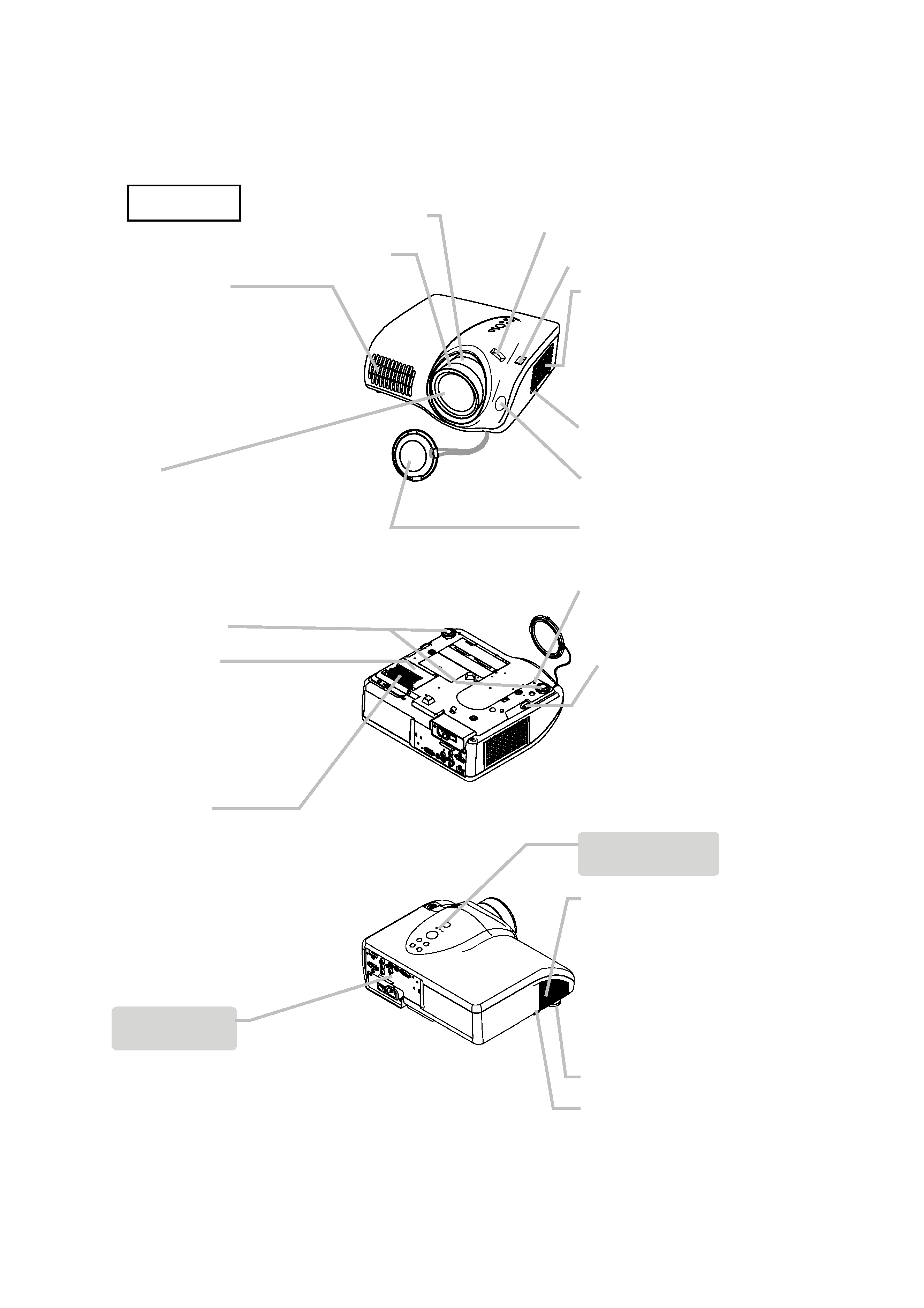
3. Names of each part
Part names
Exhaust vent
Do not block or cover the
projector's vents.
To avoid being burnt,
please do not touch areas
near the vents while the
projector is in use or
immediately after use.
Lens
A bright light for projecting is
emitted from the lens.
Please do not look into the
lens while the projector is
in use.
Elevator feet
Lamp cover
Covers the lamp.
The lamp has a finite
product life. Preparation
of a new lamp and
early replacement are
recommended.
Intake vent
Do not place anything that
may be sucked into or stick
to the vents underneath
the projector.
Zoom ring
Focus ring
(Front right view)
Filter cover
Covers the air filter and intake
vent.
Maintain the air filter to
ensure proper ventilation.
Control buttons
See next page.
Exhaust vent
Do not block or cover the
projector's vents.
To avoid being burnt,
please do not touch areas
near the vents while the
projector is in use or
immediately after use.
Ports
See next page.
Please see the
"Connecting your devices"
section for more information.
Horizontal lens shift dials
Vertical lens shift dials
Elevator button
Remote sensor
Lens cover
Strap hole
Elevator button
Elevator foot
Elevator button
(Bottom view)
(Rear left view)
Projector
4
PJ-TX200(C11H2)
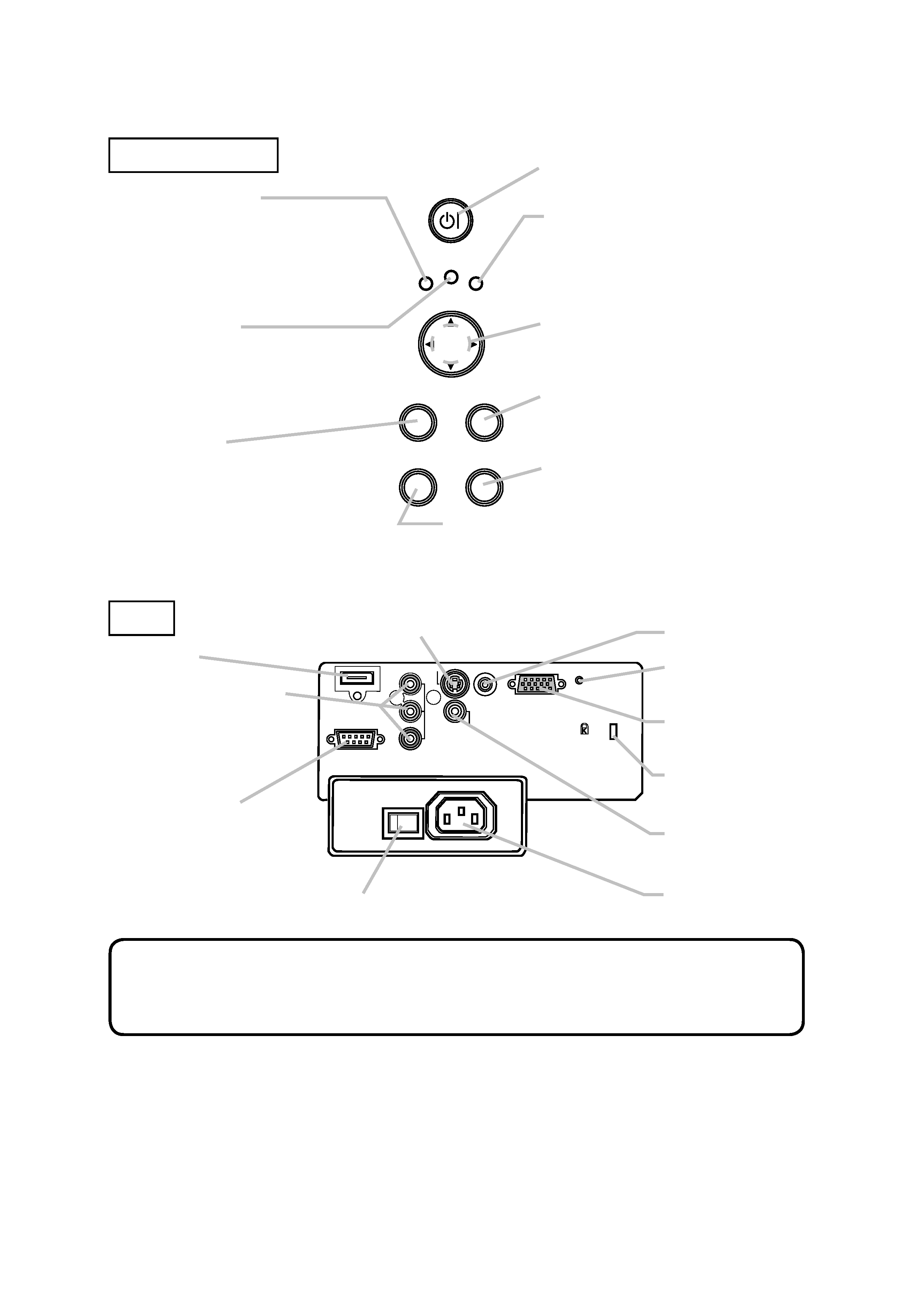
POWER indicator
This indicator blinks while the
projector is cooling down or
warming up
Note that a lit or blinking red
indicator denotes a problem.
TEMP indicator
Note that a lit or blinking red
indicator indicates a problem.
MENU button
Used to begin or end a menu
operation.
STANDBY/ON button
Used to turn the power on and off.
LAMP indicator
Note that a lit or blinking red
indicator indicates a problem.
Cursor buttons ,,,
Used to make adjustments and
operate menus.
ENTER button
Used to proceed to the next stage
in a menu operation.
RESET button
Used to cancel an adjustment.
INPUT button
Used to select an input signal. Pressing this
button toggles between input ports.
HDMI port
COMPONENT VIDEO
ports
This is a set of input
ports composed of Y, CB/
PB and CR/PR ports.
CONTROL port
S-VIDEO port
Power switch
TRIGGER port
Restart switch
COMPUTER port
Kensington lock
slot
VIDEO port
AC inlet
· Use only an HDMI cable marked with the HDMI logo for HDMI
connections.
· The TRIGGER port (12V/25mA) is used to connect to a screen that can be
controlled via a trigger signal from display equipment.
NOTE
POWER
MENU
ENTER
LAMP
TEMP
STANDBY/ON
INPUT
RESET
Y
CB/PB
CR/PR
COMPONENT VIDEO
S-VIDEO
VIDEO
COMPUTER
CONTROL
HDMI
TRIGGER
AC IN
I
O
Control buttons
Ports
5
PJ-TX200(C11H2)
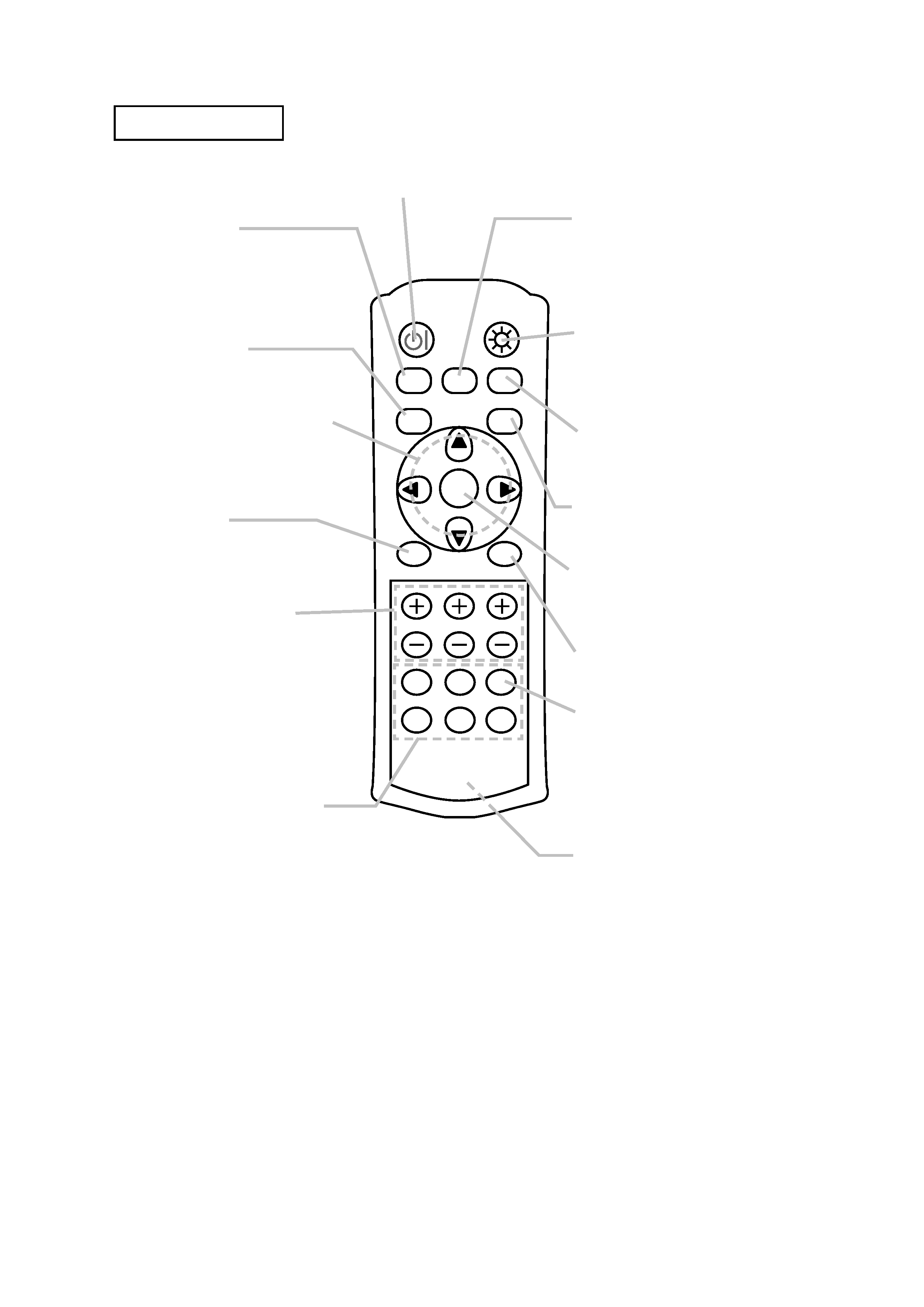
POWER button
Used to turn the power on and off.
BLACK button
Used to select a BLACK
mode. Each mode adjusts the
black setting to suit different
conditions.
ASPECT button
Used to select an aspect ratio.
Cursor buttons ,,,
Used to make adjustments
and operate menus.
MENU button
Used to begin or end a menu
operation.
CONTRAST, BRIGHT,
COLOR buttons
Used to adjust the contrast,
brightness and color tone.
PC, HDMI, COMPO,
S-VIDEO, VIDEO buttons
Used to select an input port.
PC button
COMPUTER port
HDMI button
HDMI port
COMPO button
COMPONENT VIDEO ports
S-VIDEO button
S-VIDEO port
VIDEO button
VIDEO port
MODE button
Used to select a mode. Each
mode is a combination of
settings for gamma, color
temperature and iris.
LIGHT button
Used to make the buttons on
the remote control light up for
a short time.
MEMORY button
Used to save and load user
adjustment settings.
IRIS button
Used to adjust the iris.
ENTER button
Used to proceed to the next
stage in a menu operation.
RESET button
Used to cancel an adjustment.
Battery cover
The battery cover is on the
back of the remote control.
AUTO button
Used to enable the automatic
adjustment function.
POWER
LIGHT
BLACK
ASPECT
MENU
BRIGHT CONTRAST COLOR
IRIS
MODE
MEMORY
ENTER
RESET
HDMI
PC
AUTO
COMPO
S-VIDEO
VIDEO
Remote control