SPECIFICATIONS AND PARTS ARE SUBJECT TO CHANGE FOR IMPROVEMENT.
Multimedia LCD Projector
August 2003 Digital Media Division
SM
0536
PJTX10AU
SERVICE MANUAL
Be sure to read this manual before servicing. To assure safety from fire, electric shock, injury, harmful radi-
ation and materials, various measures are provided in this Hitachi Multimedia LCD Projector. Be sure to
read cautionary items described in the manual to maintain safety before servicing.
Caution
1. When replace the lamp, to avoid burns to your fingers. The lamp becomes too hot.
2. Never touch the lamp bulb with a finger or anything else. Never drop it or give it a shock. They may
cause bursting of the bulb.
3. This projector is provided with a high voltage circuit for the lamp. Do not touch the electric parts of
power unit (main), when turn on the projector.
4. Do not touch the exhaust fan, during operation.
5. The LCD module assembly is likely to be damaged. If replacing to the LCD LENS/PRISM assembly, do
not hold the FPC of the LCD module assembly.
6. Use the cables which are included with the projector or specified.
Service Warning
1. Features --------------------------------------------------- 2
2. Specifications--------------------------------------------- 2
3. Names of each part ------------------------------------- 3
4. Adjustment ------------------------------------------------ 5
5. Troubleshooting-----------------------------------------11
6. Service points ------------------------------------------ 16
7. Wiring diagram ----------------------------------------- 29
8. Disassembly diagram--------------------------------- 34
9. Replacement parts list-------------------------------- 37
10.RS-232C communication ---------------------------- 38
11.Block diagram------------------------------------------- 46
12.Connector connection diagram -------------------- 47
13.Basic circuit diagram---------------------------------- 48
Contents
Warning
The technical information and parts shown in this
manual are not to be used for: the development,
design, production, storage or use of nuclear, chemical,
biological or missile weapons or other weapons of
mass destruction; or military purposes; or purposes that
endanger global safety and peace. Moreover, do not
sell, give, or export these items, or grant permission for
use to parties with such objectives. Forward all inquiries
to Hitachi Ltd.
(C10H)
PJTX10E
PJTX10W
2
PJ-TX10 (C10H)
1. Features
Easy and flexible keystone adjustment
My memory
Optical lens shift
Wide angle lens
Low noise
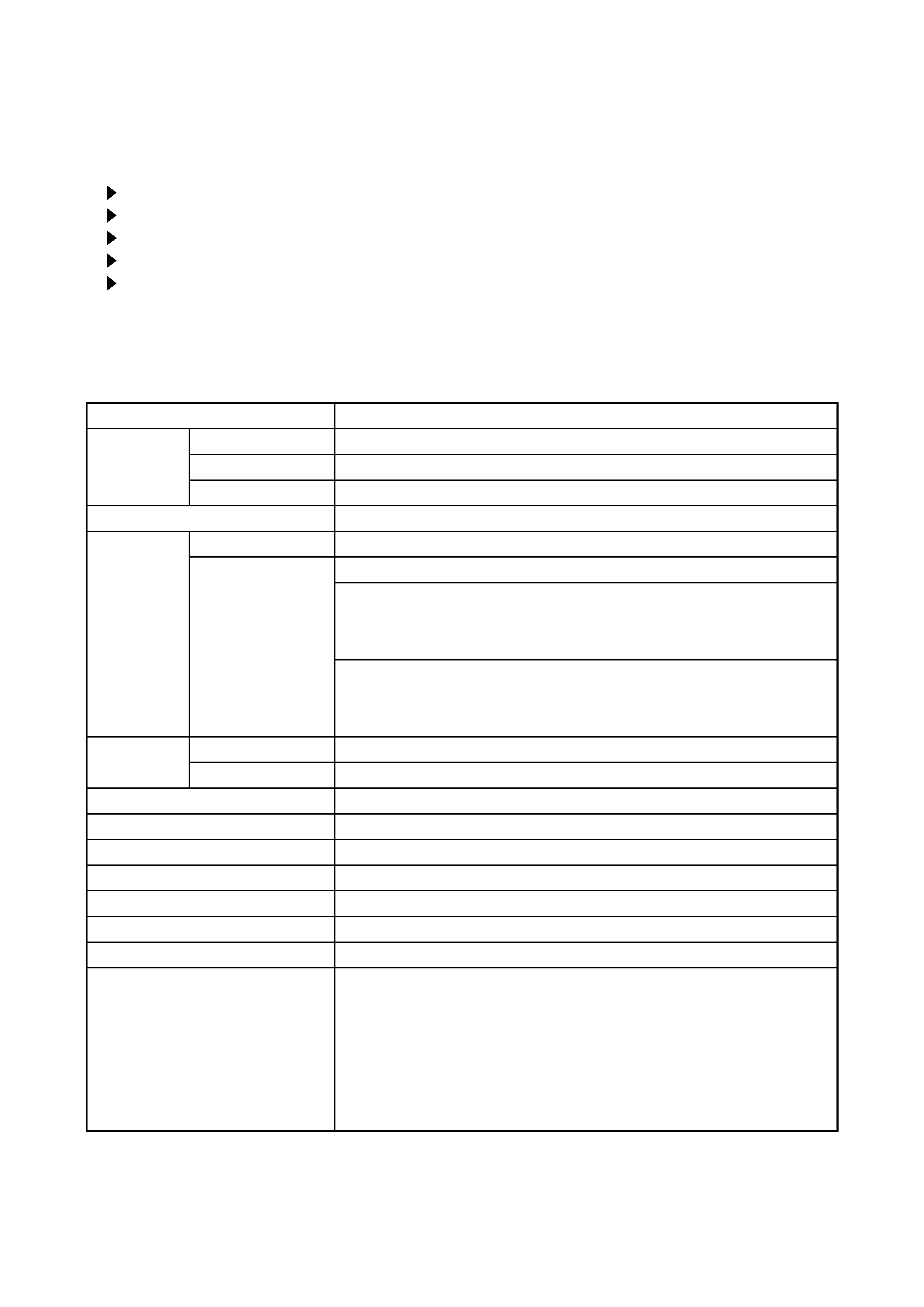
2. Specifications
Model name
PJ-TX10
Liquid
Crystal
Panel
Drive system
TFT active matrix
Panel size
1.4cm (0.55 type)
Number of pixels
854 (H) × 480 (V)
Lamp
130W UHB
Video Input
System
NTSC,PAL(BGDHI),SECAM,PAL-M,PAL-N,NTSC4.43,PAL60
Level
Composite 1.0±0.1Vp-p(75termination)
S-Video Y : 1.0±0.1Vp-p(75termination)
C : 0.286±0.1Vp-p(NTSC burst signal,75termination)
0.3±0.1Vp-p(PAL/SECAM burst signal,75termination)
Component
Y : 1.0±0.1Vp-p(75termination)
CB/PB : 0.7±0.1Vp-p(75termination)
CR/PR : 0.7±0.1Vp-p(75termination)
RGB input /
output
Analog RGB
0.7V p-p (75termination)
Sync.
TTL level
Audio Input
200mVrms,50k (max. 3.0Vp-p)
Speaker output
1.0W(mono)
Power supply
AC100~120V / 2.4A , AC220~240V / 1.1A
Power consumption
220W
Dimensions
350(W) × 121(H) × 285(D) mm (No including protruding parts)
Weight
3.6kg (7.9lbs)
Temperature
Operation : 0~35°C
Storage : -20~60°C
Accessories
Power cord
PJ-TX10W x 3 (US, UK, Europe)
PJ-TX10E x 2 (UK, Europe)
Video/Audio cable x 1
SCART adapter
PJ-TX10E only x 1
Rivet (for Lens cap) x 1
Strap (for Lens cap) x 1
Remote control x 1
Battery (for Remote control) x 2
User's manual
Quick guide x 1
Safety guide x 1
Operating guide book x 2 or 3
3
PJ-TX10 (C10H)
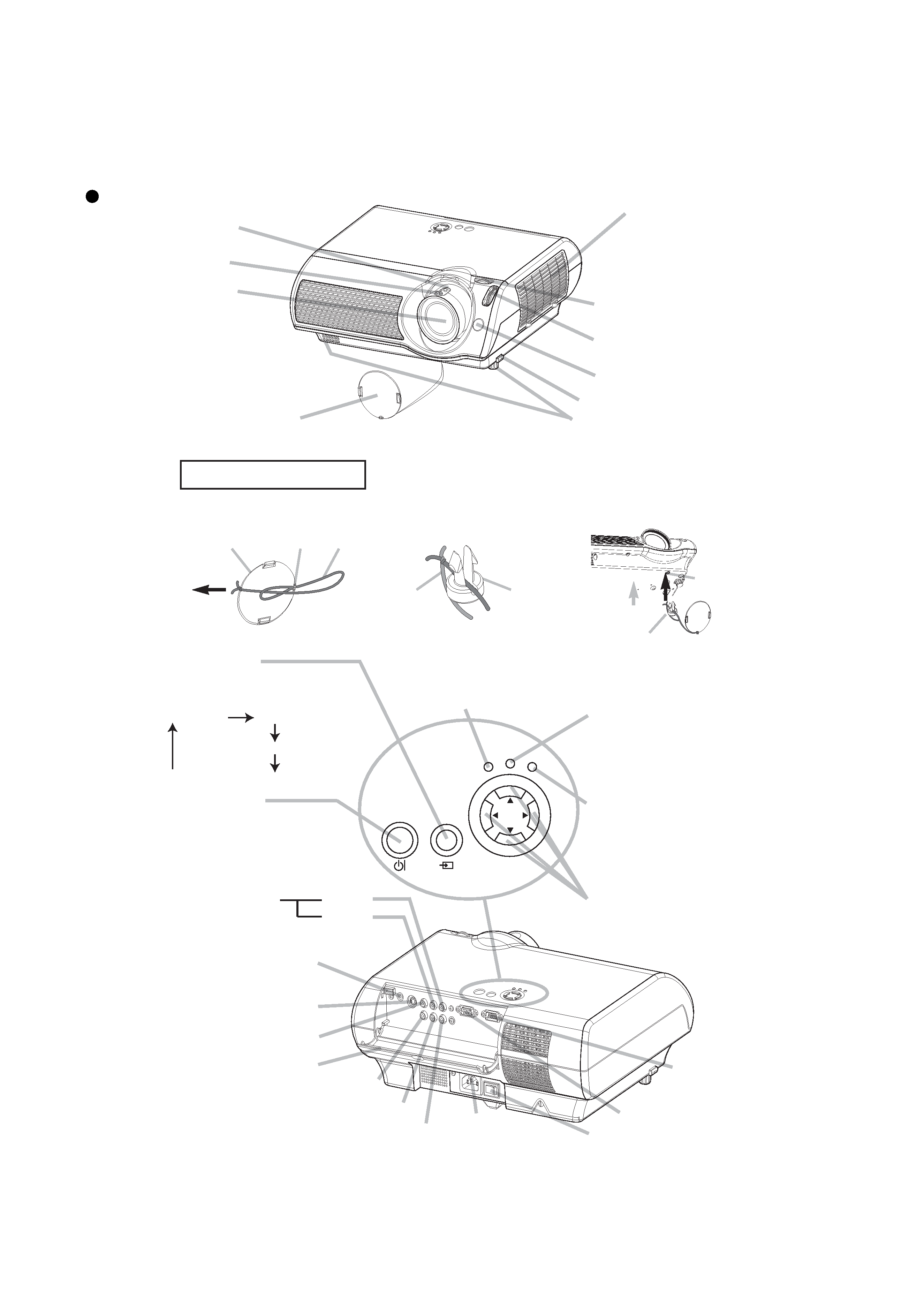
3. Names of each part
Parts names
Zoom ring
Focus ring
Air filter cover
(An air filter is
inside.)
Elevator feet
Lens cap
Lens
(The picture is
projected from
here.)
Picture shift dial
(vertical)
Picture shift dial
(horizontal)
Projector (Front/Right)
Remote sensor
Elevator button
Lens cap
Strap ring
Strap
Pull
Fastening The Lens Cap
1. Fix the strap to the strap ring
of lens cap, as the right drawing.
2. Put one piece of the strap
into the groove on rivet,
as the right drawing.
3. Push the rivet into the
strap hole.
To avoid losing, please fasten the lens cap to
the projector using the strap.
Strap
Rivet
Strap
hole
Rivet
Push in
(Bottom side)
AC inlet
VIDEO port
Ports cover
AUDIO port
(from a computer)
S-VIDEO port
COMPONENT VIDEO - Y
AUDIO
R port
L port
(from a video equipment)
Power switch
COMPUTER port
CONTROL
port
STANDBY/ON
INPUT
POWER
LAMP
TEMP
MENU
MENU buttons
operate the menu function.
TEMP indicator
lights or blinks when any
problem about internal
temperature has happened.
LAMP indicator
lights or blinks when any
problem about the lamp has
happened.
STANDBY/ON
button
prepares for turning the
power on/off. Refer to the
section "Power ON/OFF".
INPUT button
toggles between the signal
ports.
COMPUTER
VIDEO
S-VIDEO
COMPONENT VIDEO
POWER indicator
tells the state of power supply.
Refer to the section "Power
ON/OFF".
COMPONENT VIDEO - CB/PB
COMPONENT VIDEO - CR/PR
Projector (Rear/Left)
4
PJ-TX10 (C10H)
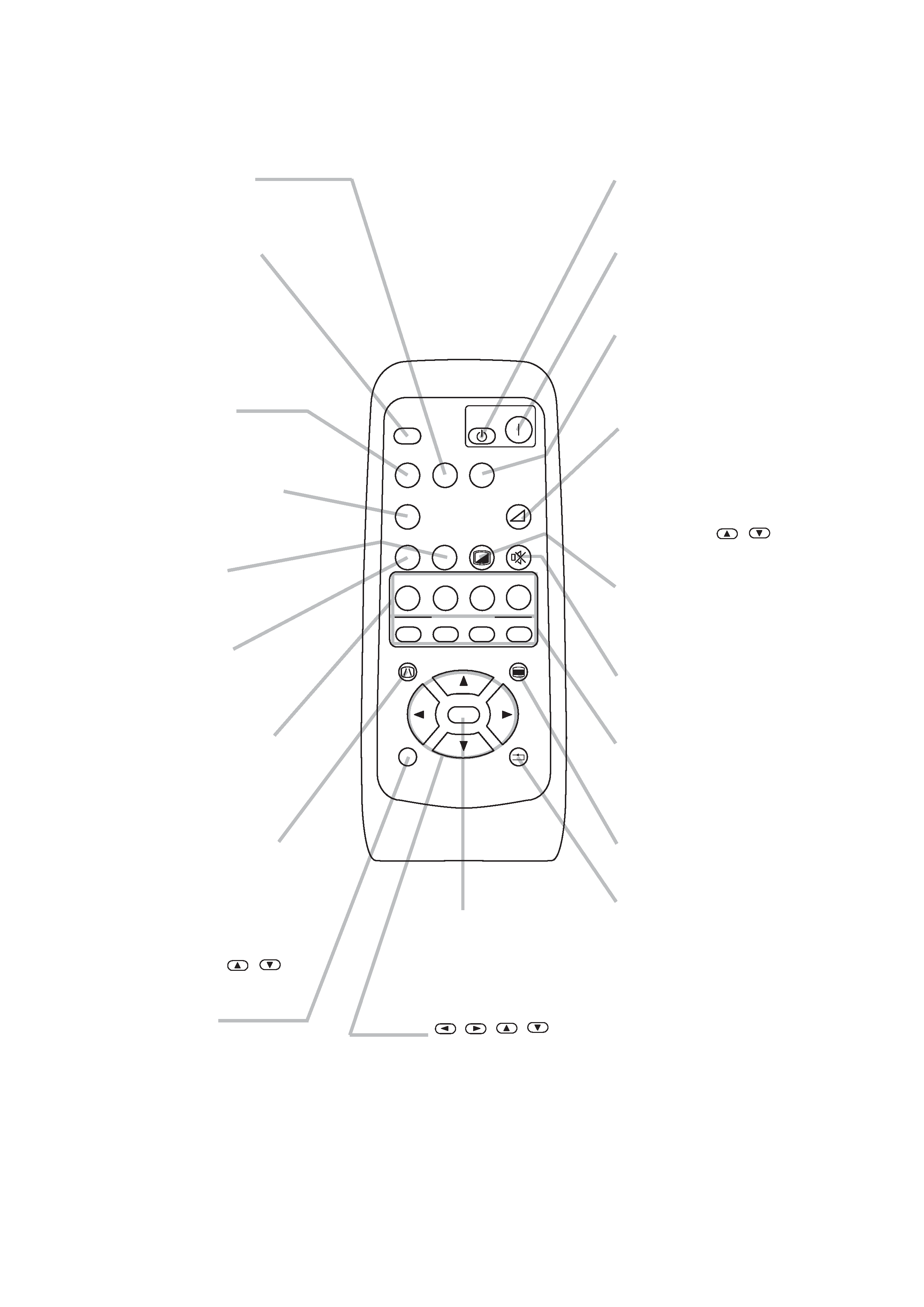
Remote control transmitter
OFF button
prepares for turning the
power off.
SEARCH button
searches for an input
signal between the
following signal ports of
COMPUTER, VIDEO,
S-VIDEO and
COMPONENT VIDEO.
MENU button
opens/closes the menu.
S-VIDEO button
selects the input signal
of S-VIDEO port.
COMPONENT
button
selects the input signal of
COMPONENT port.
VOLUME button
turns on/off the VOLUME
mode.
In the VOLUME mode,
To adjust the volume,
use the cursor
/
buttons.
MUTE button
mutes/restores the sound.
BLANK button
blanks the screen
temporarily.
M1, M2, M3, M4
buttons
call the setting data on
each memory.
VIDEO button
selects the input signal of
VIDEO port.
ON button
prepares for turning the
power on.
COMPUTER button
selects the input signal of
COMPUTER port.
WIDE button
toggles between the
modes for aspect ratio.
AUTO button
executes automatic
adjustment.
CINEMA, DYNAMIC,
NORMAL, CUSTOM
buttons
select each of gamma
mode.
KEYSTONE button
turns on/off the KEYSTONE
mode.
In the KEYSTONE mode,
To adjust the
keystone,
use the cursor
/
buttons.
ESC button
returns to the previous
display at the menu
functions.
,,,
(Cursor) buttons
works for adjusting or
menu controlling.
RESET button
cancels the adjustment in
progress.
* The adjustments of the
volume etc. are not reset.
ENTER button
proceeds to the next
operation at the menu
functions.
SEARCH
SRC
VIDEO
VSV
C
WIDE
AUTO
MUTE
BLANK
CUSTOM
CINEMA
AT
CIN
M1
E
DYNAMIC
DYN
ENT
MYMEMORY
NORMAL
NOR
CUS
WID
PC
MENU
ENTER
ESC
RESET
VOLUME
COMPUTER
COMPONENT
S-VIDEO
OFF
ON
KEYSTONE
M2
M3
M4
5
PJ-TX10 (C10H)
4-2 Ghost adjustment
Signals for internal adjustment
0/255
30%
112/255
30%
Adjustment procedure
1. Use DAC-P - GHOST - R: in the FACTORY MENU
to adjust so that R color ghost is at a minimum.
(Set the adjustment value to default, and then
raise the value. When a ghost appears to the left
of a vertical line, reduce the value by 4 steps.)
2. In the same way, use DAC-P - GHOST-G: in the
FACTORY MENU to adjust so that G color ghost
is at a minimum.
3. In the same way, use DAC-P - GHOST-B: in the
FACTORY MENU to adjust so that B color ghost
is at a minimum.
4. Adjustment
4-1 Before adjusting
4-1-1 Selection of adjustment
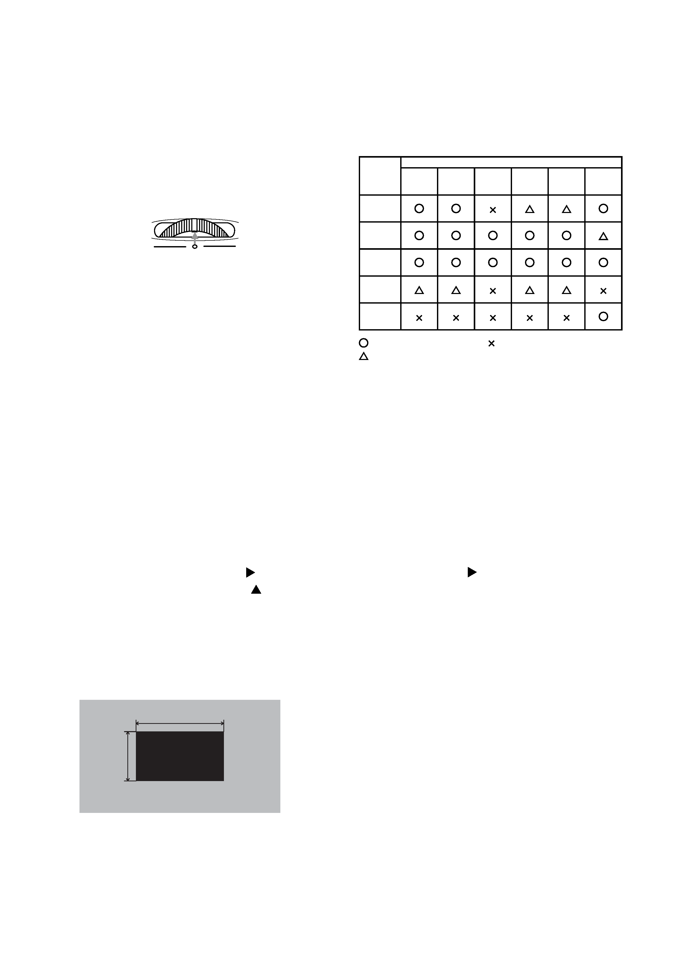
When any parts in the table 4-1 are changed, choose
the proper adjusting items with the chart.
Fig.4-1 Shifting the lens position
Table 4-1: Relation between the replaced part and adjustment
Replaced
part
Adjustment
Ghost
(Chap.4-2)
Flicker
(Chap.4-3)
NRSH
(Chap.4-4)
White
balance
(Chap.4-5)
Color
uniformity
(Chap.4-6)
AIR
SENSOR
(Chap.4-7)
Dichroic
optics unit
LCD/LENS
prism
assembly
PWB
assembly
Main
Lamp
unit
assembly
PWB
assembly
Sensor
: means need for adjustment.
: means not need for djustment.
: means recommended.
4-1-2 Setting of condition before adjustment
1. Before starting adjustment, warm up the projector
for about 10 minutes.(Blank white)
2. Set Zoom Wide to Max. And project an image
with more than 1m (40 type) in diagonal size.
3. Set the lens position to the default with horizontal
and vertical lens shift dial. As shown in Fig.4-1,
adjust the dials to match the dial's center mark to
printed center mark on case.
4. Normalizing the video adjustment.
(Press the [MENU] button of the Remote control
transmitter. Place the cursor on the RESET item
in the Main menu and press the [ ] key. After the
RESET menu appears, press the [ ] key to EXE-
CUTE the normalization. Next choose the RESET
item in the PICTURE1 menu and perform EXE-
CUTE by the same operation described above.)
*note :The MAIN and PICTURE1 menu is not
reset with no signal.
5. Set the WHISPER in the MAIN menu to the NORMAL.
6. Set the NORMAL at GAMMA in the PICTURE1
menu.
7. Perform all adjustments from the FACTORY MENU.
Perform the following operations to display the
FACTORY MENU.
a. Press the [MENU] button on the Remote control
transmitter (the MAIN menu will appear).
b. Select the [RESET] in the MAIN menu, and
then press the [ ] button.
c. Next, press the [RESET] button one time. And
hold the [RESET] button for 3 seconds or
more (the FACTORY MENU will appear).