CAUTION:
Beforeservicing this chassis, itisimportantthat the servicetechnician read the"Safety
Precautions"and"ProductSafetyNotices"inthisservicemanual.
ATTENTION:
Avantd'effectuerl'entretienduchâassis,letechniciendoitlireles«Précautionsdesécurité»
etles«Noticesdesécuritéduproduit»présentésdansleprésentmanuel.
VORSICHT:
VorÖffnendesGehäuseshatderService-Ingenieurdie,,Sicherheitshinweise"und,,Hinweise
zurProduktsicherheit"indiesemWartungshandbuchzulesen.
SERVICE MANUAL
MANUEL D'ENTRETIEN
WARTUNGSHANDBUCH
Data
contained
within
this
Service
manual is
subject
to
alteration for
improvement.
Les données fournies dans le présent
manueld'entretienpeuventfairel'objet
demodificationsenvuedeperfectionner
leproduit.
Die
in
diesem
Wartungshandbuch
enthaltenenSpezifikationenkönnensich
zwecksVerbesserungenändern.
September 2000
AV SURROUND SYSTEM
HTADD3E
HTADD3EBS
HTADD3W
HTADD3WUN
HTADD3WAU
SM0103
SPECIFICATIONS AND PARTS ARE SUBJECT TO CHANGE FOR IMPROVEMENT
CONTENTS
SPECIFICATIONS...............................................................................................................................................3
SERVICE POINTS..............................................................................................................................................4
WIRING DIAGRAM...................................................................................... .......................................................9
PRINTED WIRING BOARD..............................................................................................................................10
SCHEMATIC DIAGRAM....................................................................................................................................25
EXPLODED VIEW.............................................................................................................................................43
REPLACEMENT PARTS LIST..........................................................................................................................47
ADJUSTMENT.....................................................................................................................................................8
BLOCK DIAGRAM.............................................................................................................................................23

ENGLISH
SAFETY PRECAUTIONS
WARNING: The following precautions must be observed.
ALL PRODUCTS
Before any service is performed on the chassis an
isolation transformer should be inserted between the
power line and the product.
1. When replacing the chassis in the cabinet, ensure
all the protective devices are put back in place.
2. When service is required, observe the original
lead dressing. Extra precaution should be taken to
ensure correct lead dressing in any high voltage
circuitry area.
3. Many
electrical
and
mechanical
parts
in
HITACHI products have special safety related
characteristics. These characteristics are often not
evident from visual inspection, nor can the
protection afforded by them necessarily be
obtained by using replacement components rated
for higher voltage, wattage, etc. Replacement
parts
which
have
these
special
safety
characteristics are identified by marking with a
on the schematics and the replacement parts
list.
The use of a substitute replacement component
that does not have the same safety characteristics
as the HITACHI recommended replacement one,
shown in the parts list, may create electrical
shock, fire, X-radiation, or other hazards.
4. Always replace original spacers and maintain lead
lengths. Furthermore, where a short circuit has
occurred, replace those components that indicate
evidence of overheating.
5. Insulation resistance should not be less than 2M
ohms at 500V DC between the main poles and
any accessible metal parts.
6. No flashover or breakdown should occur during
the dielectric strength test, applying 3kV AC or
4.25kV DC for two seconds between the main
poles and accessible metal parts.
7. Before returning a serviced product to the
customer, the service technician must thoroughly
test the unit to be certain that it is completely safe
to operate without danger of electrical shock. The
service technician must make sure that no
protective device built into the instrument by the
manufacturer
has
become
defective,
or
inadvertently damaged during servicing.
CE MARK
1.
HITACHI products may contain the CE mark on
the rating plate indicating that the product
contains
parts
that
have
been
specifically
approved
to
provide
electromagnetic
compatibility to designated levels.
2.
When replacing any part in this product, please
use only the correct part itemised in the parts list
to ensure this standard is maintained, and take
care to replace lead dressing to its original state,
as this can have a bearing on the electromagnetic
radiation/immunity.
PICTURE TUBE
1.
The line output stage can develop voltages in
excess of 25kV; if the E.H.T. cap is required to be
removed, discharge the anode to chassis via a
high value resistor, prior to its removal from the
picture tube.
2.
High voltage should always be kept at the rated
value of the chassis and no higher. Operating at
higher voltages may cause a failure of the picture
tube or high voltage supply, and also, under
certain circumstances could produce X-radiation
levels moderately in excess of design levels. The
high voltage must not, under any circumstances,
exceed 29kV on the chassis (except for projection
Televisions).
3.
The primary source of X-radiation in the product
is the picture tube. The picture tube utilised for
the above mentioned function in this chassis is
specially constructed to limit X-radiation. For
continued X-radiation protection, replace tube
with the same type as the original HITACHI
approved type
4.
Keep the picture tube away from the body while
handling. Do not install, remove, or handle the
picture tube in any manner unless shatterproof
goggles are worn. People not so equipped should
be kept away while picture tubes are handled
LASERS
If the product contains a laser avoid direct exposure to
the beam when the cover is open or when interlocks are
defeated or have failed.
- 1 -
HTA-DD3
2
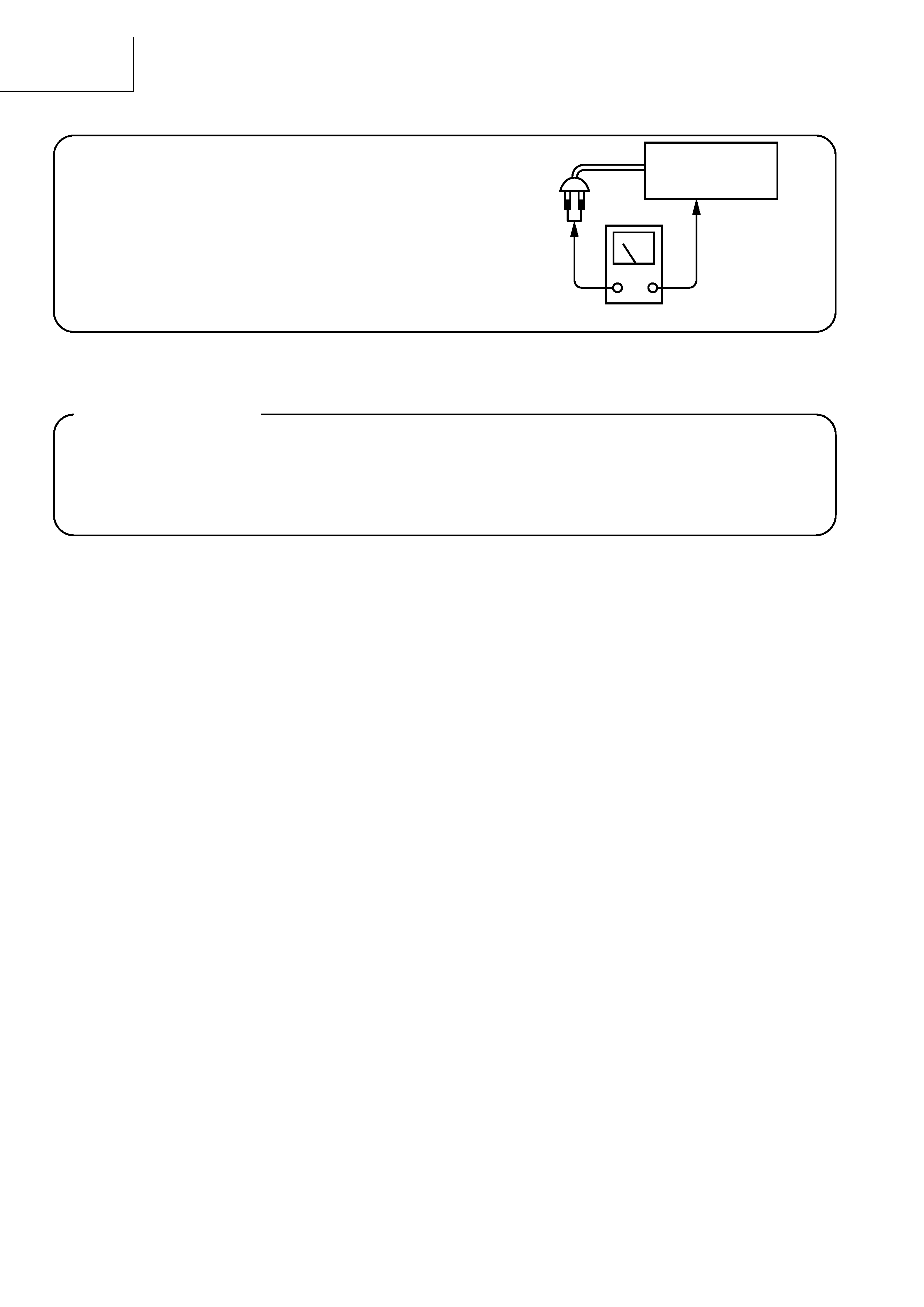
Check that exposed parts are acceptably insulated from
the supply circuit before returning the repaired instrument
to the customer.
· Checking method
Measure the resistance value between the both poles of
attachment cup (Power supply plug) and the exposed
parts (Parts such as Knob, Cover, etc. where the cus-
tomer is easy to touch.) and check that the resistance
value is 500 kohms or more.
INSTRUMENT
(Exposed part)
Insulation tester (DC 500V)
SAFETY PRECAUTIONS
The following precautions should be observed when servicing.
1. Since many parts in the unit have special safety-related characteristics, always use genuine Hitachis replace-
ment parts. Especially critical parts in the power circuit block should not be replaced with other makers. Critical
parts are marked with _ in the circuit diagram and printed wiring board.
2. Before returning a repaired unit to the customer, the service technician must thoroughly test the unit to ascertain
that it is completely safe to operate without danger of electrical shock.

HTA-DD3
3
SPECIFICATIONS
AUDIO SECTION
(Power amplifier)
For (E, EBS)
For (W, WUN, WAU)
Rated output:
Front:
80 W + 80 W (6 /ohms, 20 Hz ~ 20 kHz with 0.1 % T.H.D.) 100 W + 100 W (EIAJ, 6 ohms)
Centre:
80 W
(6 /ohms, 20 Hz ~ 20 kHz with 0.1 % T.H.D.) 100 W (EIAJ, 6 ohms)
Surround:
80 W + 80 W (6 /ohms, 20 Hz ~ 20 kHz with 0.1 % T.H.D.) 100 W + 100 W (EIAJ, 6 ohms)
SINUS power:
Front:
90 W + 90 W (6 /ohms, 1 kHz, 0.1 %)
Centre:
90 W
(6 /ohms, 1 kHz, 0.1 %)
Surround:
90 W + 90 W (6 /ohms, 1 kHz, 0.1 %)
Output terminals:
Front:
A or B
6 to 16 /ohms
A + B
12 /ohms or more
Center/Surround:
6 to 16 /ohms
(Analog)
LINE input
Input sensitivity / input impedance:
200 mV / 47 k/kohms
Frequency response:
10 Hz ~ 50 kHz: +1, 3 dB
S/N ratio:
93 dB (IHF-A weighted)
Total harmonic distortion:
0.1% (20 Hz ~ 20 kHz)
PHONO input-REC OUT
Input sensitivity / input impedance:
2.5 mV / 47 k/kohms
RIAA deviation:
±1 dB (20 Hz ~ 20 kHz)
S/N ratio:
74 dB (IHF-A weighted, with 5mV input)
Total harmonic distortion:
0.03% (1 kHz, 3V)
Rated output / Maximum output:
150 mV / 7V
· VIDEO SECTION
(Composite)
Input/output level and impedance:
1 Vp-p, 75 /ohms
Frequency response:
5 Hz ~ 10 MHz +1, 3 dB
(S-Video)
Input/output level and impedance:
Y=1 Vp-p, C=0.286 Vp-p
Frequency response:
5 Hz ~ 10 MHz +1, 3 dB
(Component)
Input/output level and impedance:
Y=1 Vp-p, CB=0.7 Vp-p, CR=0.7 Vp-p
Frequency response:
5 Hz ~ 10 MHz +1, 3 dB
· TUNER
SECTION
[FM]
(note: µV at 75/ohms, 0 dBF = 1 10-15W) [AM]
Receiving range:
87.50 MHz ~ 108.00 MHz (0.05 MHz step)
522 kHz ~ 1611 kHz (9 kHz step) (E, EBS)
522 kHz ~ 1611kHz (9 kHz step),
520 ~ 1710 kHz (10 kHz step) (W, WUN,WAU)
Usable sensitivity:
2.0 µV (17.2 dBf)
600 µV
50 dB quieting sensitivity:
STEREO
23µV (38.5 dBf)
S/N ratio:
MONO
80 dB (IHF-A weighted)
STEREO
75 dB (IHF-A weighted)
Total harmonic distortion:
MONO
0.2% (1kHz)
STEREO
0.4% (1kHz)
· GENERAL
Power supply:
AC 230V, 50 Hz (E,EBS), AC 110 ~ 127V/220 ~ 240V, 50/60 Hz (W, WUN,WAU)
Power consumption:
180 W (Standby mode = 1.5W)
Maximum external dimensions:
434 (W) 144 (H) 320 (D) mm
Weight:
8.1 kg
· REMOTE CONTROL UNIT (RB-DD1S)
Batteries:
R6P/AA Type (two batteries)
External dimensions:
54 (W) 172 (H) 27.2 (D) mm
Weight:
100 g (including batteries)
· Accessory supplied:
Operating instructions, Remote control unit (RB-DD1S),
R6P/AA batteries, AM loop antenna and FM indoor antenna
* For purposes of improvement, specifications and design are subject to change without notice.
HTA-DD3
4
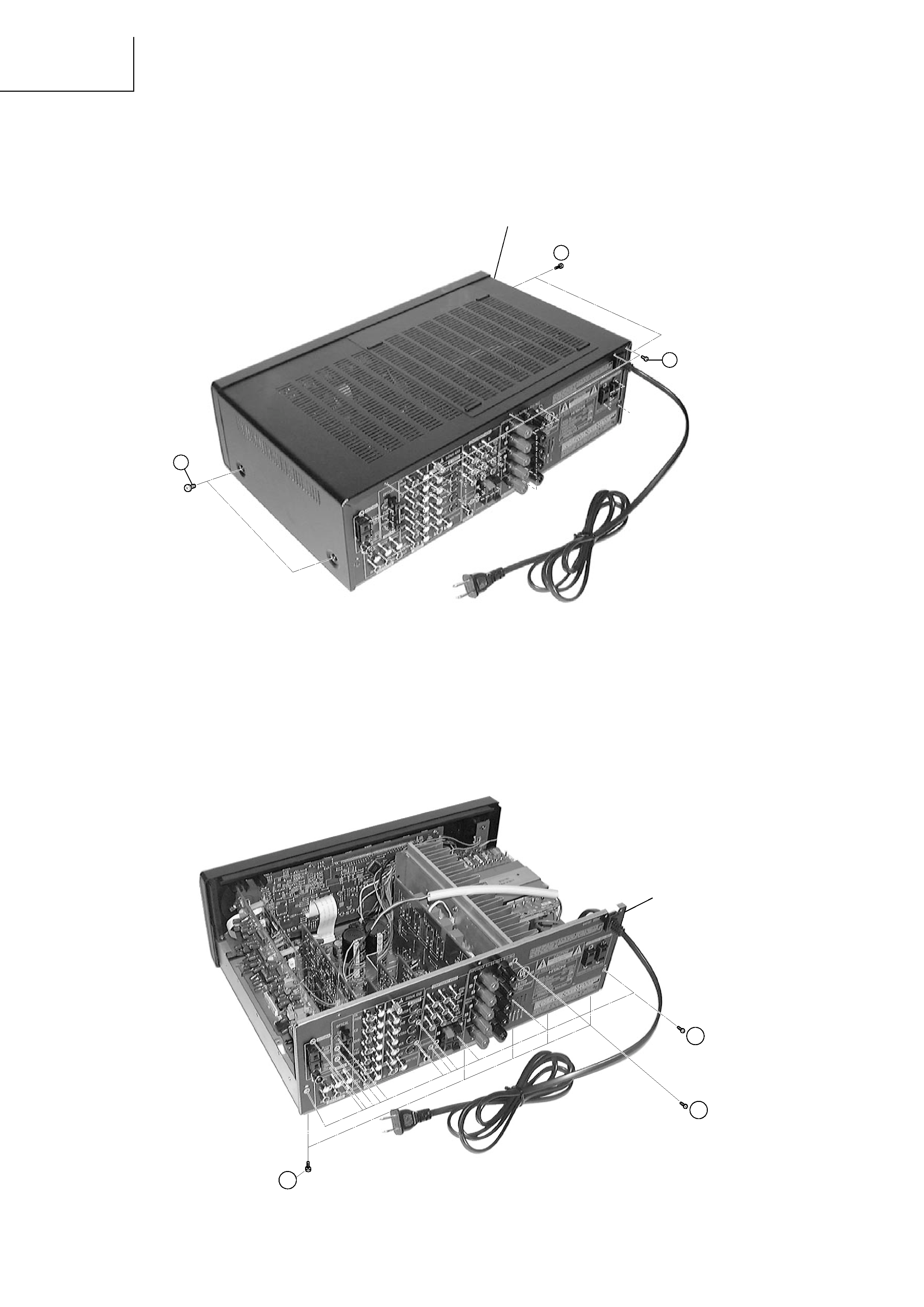
1
2
1
Top cover
x 2
x 2
x 4
Rear Plate
3 x 28
4 x 1
21
x 5
Fig.1
Fig.2
SERVICE
POINTS
1. Removal of Top Cover
(a)Remove 2 screws 1 from each side.
(b)Remove 4 screws 2 from the rear plate.
2. Removal of Rear Plate
(a)Remove 28 screws 3 and 1 screw 4 from the rear plate.
(b)Remove 5 screws - from the Bottom Chassis.