1
JVC HR-J635
U-View Limited
Recommended Safety Parts
Item
Part No.
Description
105
PEACO300-02
RE CABLE
106
PQ21953C-3
REMOTE CONTROLLER
110
PU30425-1790
INSTRUCTIONS
151
PQ11676-7
TOP COVER
159H
PDZ0141-1-2
STATOR ASSEMBLY
160
PQ11666-3-14
BOTTOM CHASSIS
161
PQ11668-2
BOTTOM COVER
173
QMP51K0-170
POWER CORD
177
PQ46485
SPACER(SAFETY)
61
PU60628-3-2
LOADING MOTOR
68
PU61487-2
CAPSTAN MOTOR
R957
QRZ0077-101X
FUSIBLE RESISTOR 100
2,1/4W
C901
QFZ9022-333
F CAPACITOR 0.033
µF
C9030
FZ9022-333
F CAPACITOR 0.033
µF
C911
QCZ9026-222
CAPACITOR 0.0022
µF
CF701
PEVB0594-Z
RESONATOR
Xl
PEVB0658
CRYSTAL RESONATOR
X701
PEVB0422
CRYSTAL RESONATOR
PC901
P52561L-1(WL)
PH COUPLER
T301
PELN0860
OSC TRANSFORMER
T302
PELN0861
OSC TRANSFORMER
T901
PELN1173
SW TRANS
HS1
P045788-1-1
HEAT SINK, Q901
TU2
PERF0258
IF UNIT
TU1001
PERF0201
TUNER UNIT
FC901
PEMC0965-Z
FUSE CLIP
FC902
PEMC0965-Z
FUSE CLIP
LF901
PELN1204
LINE FILTER
LF902
PELN0876
LINE FILTER
CN901
PU60250-2
CONNECTOR, (1-2)AC IN
CP701
ICP-N25
CIRCUIT PROTECTOR
CP901
ICP-N20
CIRCUIT PROTECTOR
CP902
ICP-N25
CIRCUIT PROTECTOR
CP1101
ICP-N15
CIRCUIT PROTECTOR
F901
QMF51E2-1R25J1
FUSE T1.2A
X1502
PEVB0660
CRYSTAL RESONATOR
X1901
PEVB0551
CRYSTAL RESONATOR
106
REMOTE CONTROLLER
PQ219530-3PQ21 953F-3
110
INSTRUCTIONS
PU30425-1790 PU30425-1799
T301
OSC TRANSFORMER
PELN0860
PELN0832
T302
OSC TRANSFORMER
PELN0861
151
PQ11676-7
TOP COVER
159H
PDZ0141-1-2
STATOR ASSEMBLY
160
PQ11666-3-14
BOTTOM CHASSIS
161
PQ11668-2
BOTTOM COVER
173
QMP51K0-170
POWER CORD
177
PQ46485
SPACER (SAFETY)
Matrix
Item
See Model
Book
OSD Diagram ......................................................................................... HR-J 435
6
General Information
Also Covers
HR-A630 & HR-A631
Service Notes
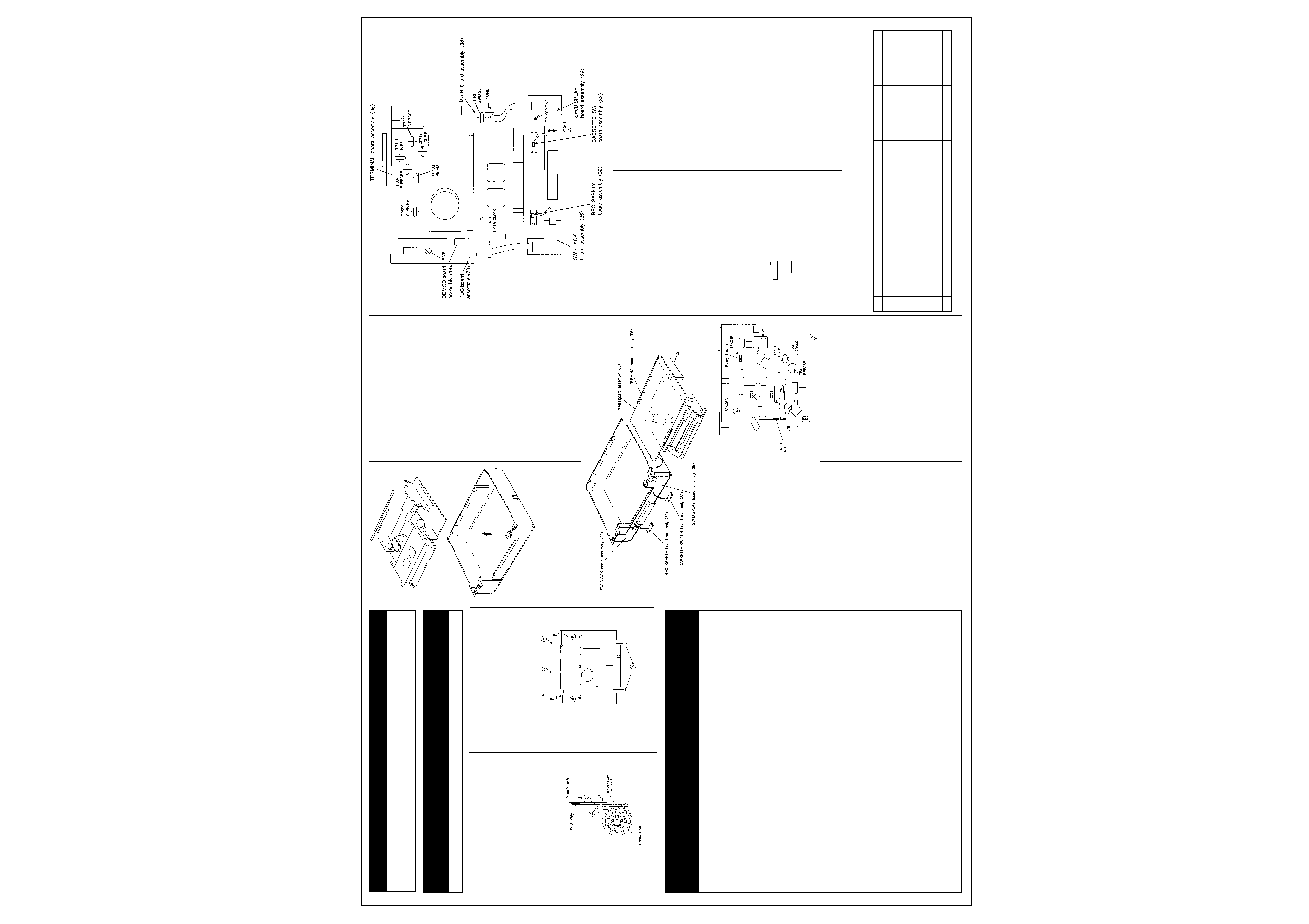
CASSETTE HOUSING INSTALLATION
NOTE: Observe the mechanical phase and
position (see figure) when installing the cassette
housing assembly. If these are incorrect, the
system will not operate properly even when tape
is inserted.
1. Check that the hole of the control cam are
aligned to the deck hole. If necessary, turn the
mode motor belt by hand to adjust the
position.
Fig. 1-4-1
SERVICE POSITION
How to take out the Mechanism and Main board
assemblies.
1) Remove the Top cover, Front panel assembly,
CN1201 and CN1204 SW DISPLAY board
assembly.
2) Take out 4 screws (A) 2 screws (B) and 1
screw (C) as shown in Fig.1-5-1.
Fig. 1-5-1
3) Remove the Mechanism assembly (including
Cassette housing) and Main board assembly
out of the chassis as shown in Fig.1-5-2.
Fig. 1-5-2
5) Turn over the Mechanism assembly and Main
board assembly then connect CN1201 and
CN1204 of the SW/DISPLAY board assembly.
6) Carry out checks & repairs as necessary as
shown in Fig.1-5-3.
Fig. 1-5-3
Cautions on cassette loading when mechanism
is in service position
The REC SAFETY board assembly of this set
serves both for detecting the safety tab (erasure
prevention tab) of a cassette and detecting a
cassette loaded. Therefore, cassette loading in
the condition that the mechanism is disassem-
bled from the set needs manual operation of the
switches of the REC SAFETY board assembly
and the CASSETTE SWITCH board assembly.
Cassette loading and ejecting procedures when
mechanism is in service position
1) Insert a cassette tape halfway into the
cassette housing assembly.
2) Press the switch of the REC SAFETY board
assembly to turn on.
3) When the cassette loading begins and the
cassette goes down to the bottom, immedi-
ately press the switch of the REC SAFETY
board assembly to turn off and hold the status
that the switch of the CASSETTE SWITCH
board assembly is turned on. (Fix the switch
with adhesive tape or put a screwdriver, etc.
on it to leave the switch in the ON status.)
Note: When input the AUDIO/VIDEO signal from
connector, connect CN1204 of the SW/JACK
board assembly.
4) In this status, desired operations (recording,
playback, fast forward, rewind, etc.) can be
performed.
Note: When the mechanism is in the service
position, the safety tab of cassette tape is not
detected and recording on cassette tapes
without safety tab is possible.
Therefore, carefully choose a cassette tape for
operation in this mode so as to avoid using
cassette tapes of important recording.
(5) For ejecting the cassette in this status, do it
in the reverse order of cassette loading men-
tioned above.
Note: If the manual operation REC SAFETY
switch timing is incorrect, the cassette may be
completely or partially elected, and the cassette
is often ejected incompletely. In such a case, it
is possible to take out the cassette by hand.
If it is desired to load a cassette again after the
cassette is ejected in the above procedure,
make sure to set the tray of the cassette
housing assembly in the frontmost position prior
to loading the cassette once again.
Opening on the chassis.
The chassis assembly has openings for easy
access to the checkpoints and connector pins as
shown in Fig.1-5-4.
Fig. 1-6-1
3) Connect TP1202 (GND) and TP1201 (TEST)
on the SW/DISPLAY board assembly with a
jump wire.
4) Connect VCR to AC.
5) Press the POWER button.
6) Select the desired operation modes with the
operation buttons or remote controller.
EMERGENCY DISPLAY FUNCTION
This product has the function to store the last
two previous emergency faults which can be
displayed in the FDP when servicing.
How to display record of an emergency faults
1) Press "N" button of the presetting unit more
than 2 seconds. and the two previous
emergency faults are shown in the FDP.
2) Press "N" button of the presetting unit again
when return the normal mode.
(Example) E : 01 : 03
Emergency faults before last
Emergency faults of the last time
(Example) E:--:--
No record of emergency
How to clear emergency record
Press the COUNTER RESET button on the
remote controller in the emergency record
display mode,and the record of the emergency
fault(s) is cleared.
PREPARATION
Precautions
1) Disconnect VCR from AC power before
soldering.
2) Avoid imparting stress to wires when disen-
gaging connectors.
3) Determine and correct the cause of difficulty
before proceeding to adjustments. Do not
disturb settings unnecessarity.
4) Use care not to damage tabs,claws,etc during
repairs.
5) Install the cassette housing assy only when
the mechanism is in the MECHANISM
ASSEMBLING MODE position.
6) When installing the Front panel assy,be sure
to engage the housing door with the door
opener of the cassette housing assy. If this is
omitted,the cassette door will not open at
Eject and the cassette can not be removed.
Check without cassette housing assy.
Mechanism operations can be observed easily
by removing the cassette housing assy. Use the
MECHANISM SERVICE MODE. When the deck
enters the emergency mode with cassette tape
loaded and it can not be ejected by pressing the
EJECT button take out of the cassette tape
according to the following procedure.
1) Disconnect the power cord from AC outlet
then take out the Top cover and Front panel
assy.
Fig. 1-5-4
MECHANISM SERVICE MODE
This model has a unique function to enter the
mechanism into every operation mode without
loading of any cassette tape. This function is
called the MECHANISM SERVICE MODE.
How to set the MECHANISM SERVICE MODE
1) Disconnect VCR from AC.
2) Remove the Top cover, Front panel assembly
and cassette housing assembly.
Detail of emergency faults
FDP
Symptom
Detect mode
Resulting mode
E:01
Loading motor rotates for more than 8 Sec without shift to next mode.
Loading
POWER OFF
E:02
Loading motor rotates for more than 8 Sec without shift to next mode.
Unloading
POWER OFF
E:03
TU REEL FG input is absent (for more than 4 Sec)
REC/PLAY/FF/REW
STOP POWER OFF
SEARCH FF/SEARCH
REW
E:04
DRUM FF input is absent (for more than 3 Sec)
REC/PLAY/FF/REW
STOP
SEARCH FF/SEARCH
REW
E:06
CAPSTAN FG input is absent (for more than 1 Sec)
REC/PLAY/FF/REW
STOP POWER OFF
F:07
No SWD5V/12V
POWER ON
POWER OFF
Table 1-7-1 EMERGENCY FAULTS
2
JVC HR-J635
www.u-view.co.uk
How to set the exclusive mechanism operation
mode (MECHANISM ASSEMBLING MODE)
1) Turn the mode motor belt by hand
2) Confirm that the hole of the control cam are
aligned to the deck hole as shown in Fig 2-4-1.
Fig. 2-4-1
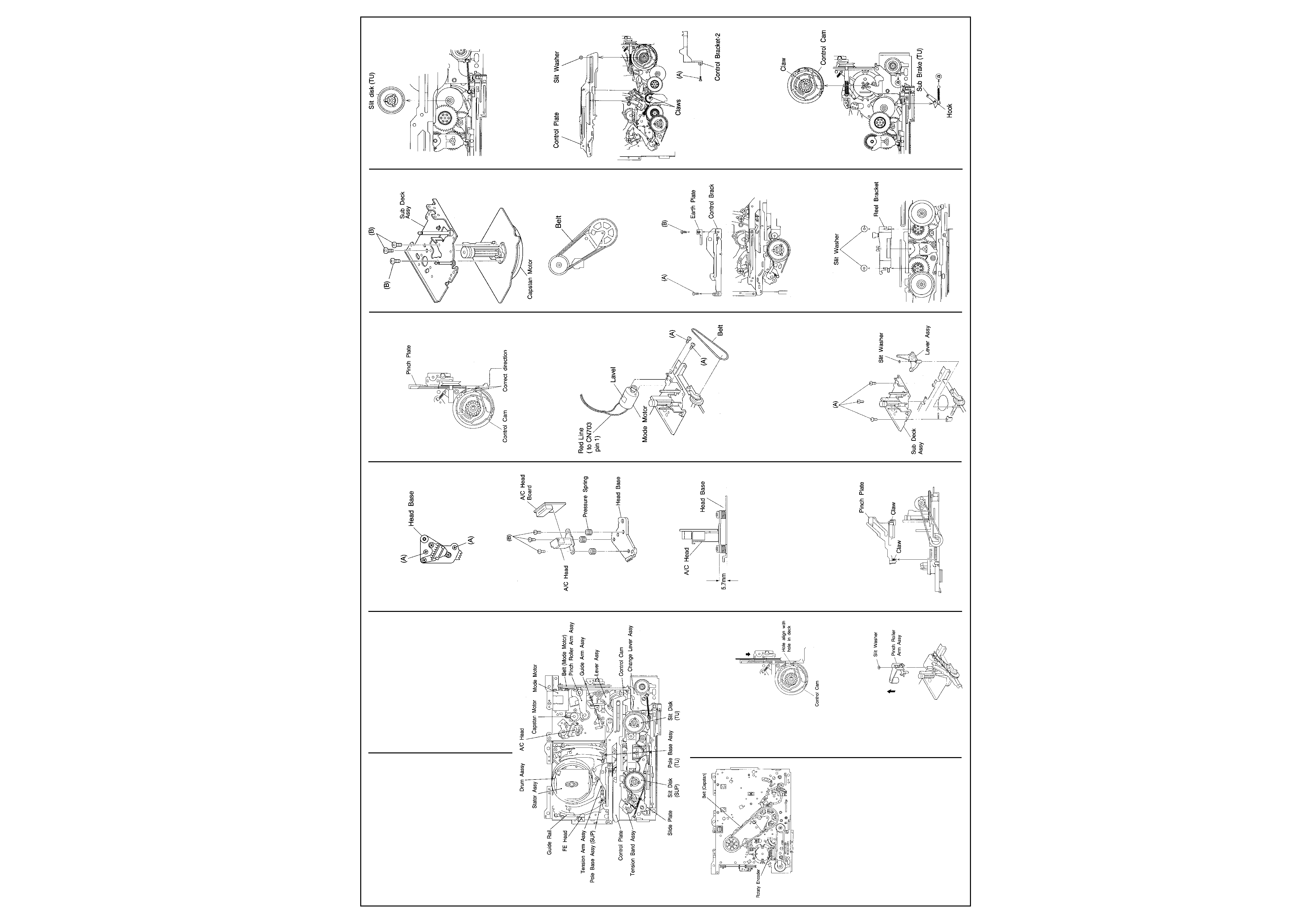
MAIN PARTS REPLACEMENT OF
MECHANISM
Pinch Rollar Arm ASSY
1) Remove the slit washer
2) Tilt up the pinch rollar assy in direction of
arrow
Fig.2-5-1
2) Turn the mode motor on the Main deck assy
by hand in the unloading direction to where
the pole base assy (supply and take-up) is
positioned below the cassette tape. At that
time, pay careful attention to the tape not to
get soiled with grease.
3) Take out 4 screws of the cassette housing
assy.
4) Remove the cassette housing with slackened
tape and guard panel of cassette.
5) Wind up the tape by turning the reel
hub(either supply or take-up side for conven-
ience) from the bottom of the cassette, and
remove the cassette tape.
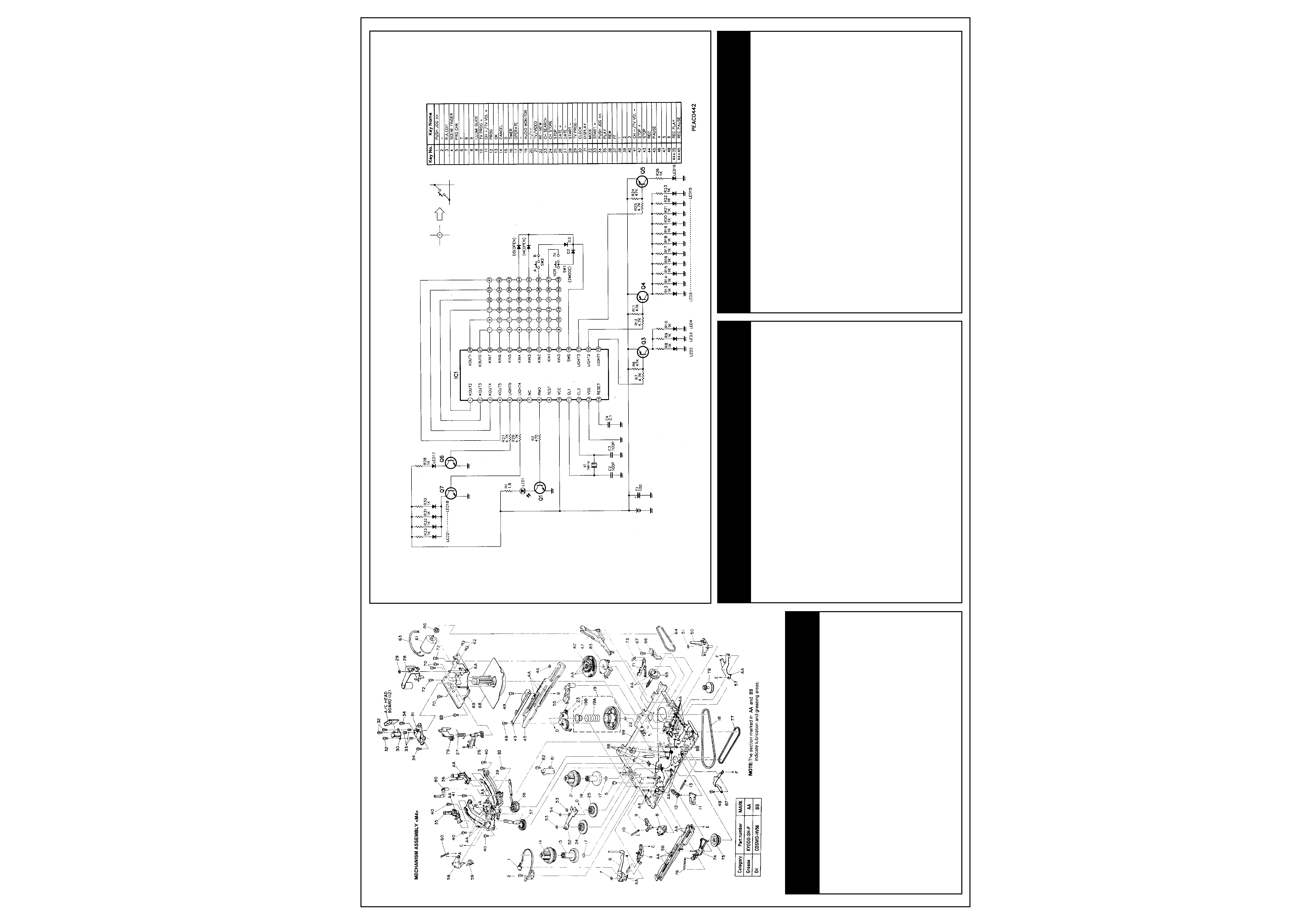
MAIN MECHANISM PARTS
Fig. 2-2-1 Top view of main deck
Fig. 2-2-2 Bottom view of main deck
Lubrication
Oil and grease do not normally require periodic
replenishing. Apply only when replacing
lubricated parts (also clean) and replace
lubrication of mating parts if soiled). For parts
and points to apply oil and grease, refer to the
exploded views of the mechanism assy. Before
oiling, clean with alcohol. Apply one or two
drops of oil. Avoid excess oil.
1. Table 2-2-1 indicates the oil and grease used
in this set. Use these or recommended locally
available equivalents.
Category
Part No.
Oil
COSMO-HV56
Grease
KYODO-SH-P
Table 2-2-1
2. Grease is not required for a replacement
A/C Head
1. Removal
1) Take out 2 screws (A).
2) Remove the NC head with head base.
Fig. 2-5-2
3) When replacing the A/C head only, remove 3
screws (B), use care not to misplace the 3
Fig. 2-5-3
2. Installation
1) Temporarily set NC head height as indicated
in Fig. 2-5-4.
Fig. 2-5-4
NOTES:
It is very important to correctly adjust the control
pulse and audio signal in addition to the
mechanical tape path. Perform interchangeabil-
ity adjustments after electrical adjustments.
Pinch Plate
1. Removal
1) Disengage 2 claws, then remove the pinch
plate.
Fig. 2-5-5
Mechanism Adjustments
Cont'd
2. Installation
1) When installing pinch plate,align rack of pinch
plate and triangle mark of control cam as
indicated in Fig.2-5-6.
Fig. 2-5-6
Mode Motor
1) Disengage the belt between mode motor and
worm gear.
2) Take out 2 screws (A) then remove the mode
motor.
Fig. 2-5-7
Lever Assy,Sub Deck Assy,Capstan Motor
1) Take out 1 slit washer then remove the lever
assy.
2) Disengage the belt (capstan motor) from
bottom of mechanism assy first as indicated
in Fig. 2-5-10.
3) Take out 3 screws (A) and remove the sub
deck assy as indicated in Fig. 2-5-8.
4) Take out 3 screws (B) and remove the
capstan motor from the sub deck assy as
indicated in Fig. 2-5-9.
Fig.2-5-8
Fig. 2-5-9
Fig. 2-5-10
Control Bracket - 1, Earth Plate
1) Take out 1 screw (A) and 1 screw (B).
2) Remove the control bracket -1 and earth
plate.
Fig.2-5-11
Reel Bracket,Slit disk (take-up)
1) Take out 2 slit washers.
2) Remove the reel bracket and slit disk(take-
up).
Fig.2-5-12
Fig.2-5-13
Control Bracket-2,Control Plate
1) Take out 1 screw (A) and remove the control
bracket-2.
2) Take out 1 slit washer.
3) Disengage 2 claws and remove the control
plate.
Fig.2-5-14
Sub Brake(take-up),Control Cam
1) Disengage 1 spring (a) and 1 claw then
remove the sub brake (take-up).
2) Disengage 1 claw and remove the control
cam.
Fig.2-5-15
cassette housing assy, as this has been applied
at the factory.
Note: Stir grease that has been stored for an
extended period.
DISASSEMBLY/ASSEMBLY PROCEDURE OF
MECHANISM
Precaution before disassembling mecha-
nism
This mechanism has an exclusive operation
mode provided for disassembling and installa-
tion of to set the mechanism to this mode before
disassembly and installationThe exclusive
mechanism operation mode is not generally
used and becomes available by manual setting
only. Then this procedure starts with the
condition that the cabinet parts,cassette
housing assy and PRE/REC board assy have
been removed.
3
JVC HR-J635
U-View Limited
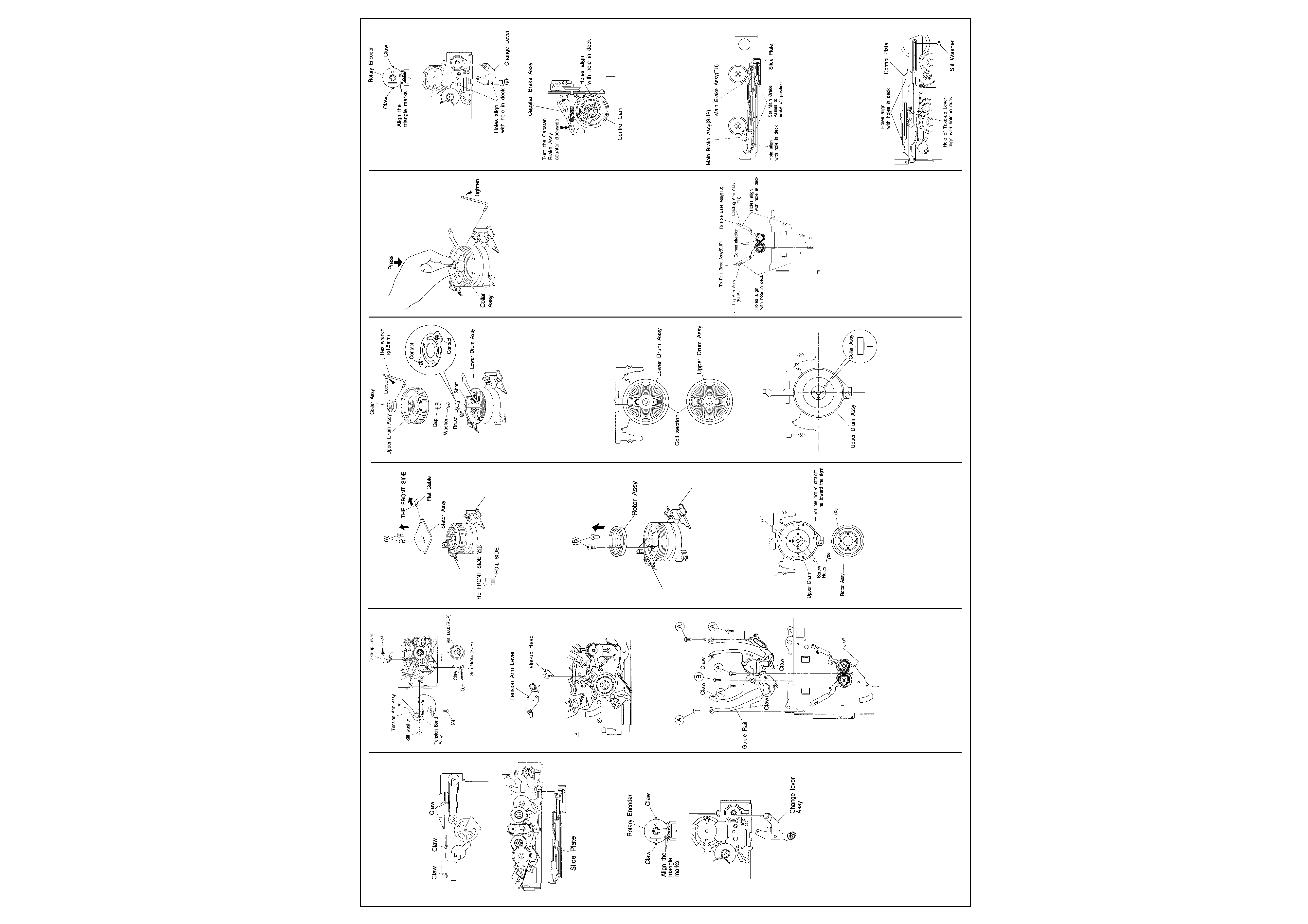
Slide Plate
1) Disengage 7 claws from bottom of the
mechanism assy and remove the slide plate.
Fig. 2-5-16
Fig. 2-5-17
Change Lever,Rotary Encoder
1) Remove the change lever.
2) Disengage 2 claws and remove the rotary
encoder.
Fig. 2-5-18
Sub Brake (supply),Tension Band Assy,Tension
Arm Assy,Take-up Lever Assy,Slit Disk(supply)
1) Disengage 1 spring (a).
2) Disengage 1 claw and remove the sub brake
(supply).
3) Take out 1 screw (A),spring (c) and slit
washer.
4) Remove the tension arm assy with tension
band assy.
5) Disengage 1 spring (b) and remove the take-
up lever assy.
6) Remove the slit disk(supply.
Fig. 2-5-19
Take-up Head,Tension Arm Lever
(1) Remove the take-up head and tension arm
lever.
Fig .2-5-20
1) Take out 5 screws (A) and 1 screw (B).
2) Disengage 4 claws and remove the guide rail.
Fig. 2-5-21
Stator Assy
1) Take out 2 screws (A).
2) Raise the stator assy in the direction indi-
cated by the arrow to remove it.
3) Remove the flat cable.
4)To reinstall,first secure the flat cable,then
insert 2 screws (A).
5) After reinstalling, be sure to perform PB
switching point adjustment (See SECTION 3
ELECTRICAL ADJUSTMENT).
Fig. 2-5-22
NOTE: When refitting the connector, check that
the flat wire is inserted correctly.
Rotor Assy
1) Remove the stator assy.
2) Take out 2 screws (B) and remove the rotor
assy.
Fig. 2-5-23
3) Align the upper dum assy and rotor assy
phase as indicated in Fig.2-5-22.
4) Overlap holes (a) of the upper drum assy with
holes (b) of the rotor assy (align holes in 3
locations) and secure with 2 screws (B) as
indicated in Fig.2-5-21.
Fig. 2-5-24
Upper Drum Assy
1. Removal
1) Remove the stator assy and rotor assy.
2) Use a 1 .5 mm hexagonal wrench to loosen
the collar assy screw and remove the collar
assy.
3) Remove the upper drum assy and use
tweezers to remove the Washer.
Fig. 2-5-25
NOTE: If the Brush is replaced, do not apply the
grease to the contacts.
2. Installation
1) Use an air brush to clean the lower drum assy
and the coil section of the new upper drum
assy.
2) Set a new washer on the drum shaft as
indicated in Fig. 2-5-25.
NOTE: Be sure to use the new washer when
replace the upper drum assy.
Fig. 2-5-26
3) Note the top and bottom of the collar assy
and determine the position as indicated in
Fig.2-5-25.
Fig .2-5-27
4) While pressing the collar assy evently from
above with your fingertips, secure the
hexagonal screw.
5) After installing,gently turn the upper drum by
hand and confirm normal rotation.
6) Install the rotar assy and stator assy.
7) Clean the upper and lower drum assies and
perform the following adjustments;
· PB switching point adjustment
· Slow tracking preset adjustment
· Interchangeability adjustment (be sure to
check LP mode)
Fig. 2-5-28
CHECKUP AND ADJUSTMENT OF
MECHANISM PHASE
Precaution
The rotary encoder and syscon circuit are
closely interrelated.Therefore,the rotary encoder
and control cam conection determines the
operations of mechanical parts such as plates,
gears, brakes, etc.Correct positioning of these
parts is essential for smooth tape loading and
mechanical operations.
Loading Arm Assy (supply,take-up)
1) Install the supply loading arm assy and the
take-up loading arm assy so that their
positioning markings on the respective gear
face each other and the holes of their arms
correspond to the holes on the main deck
assy respectively.
2) After setting the guide railsengage the pole
base assies with the tip of the loading arms
respectively. Then enter the mechanism into
the unloading mode to return the pole base
assies to the front position.
3) Reassemble the peripheral parts of the guide
rail as originally.
Fig. 2-6-1
Rotary Encoder, Change Lever, Control Cam
1) When reinstalling the rotary encoderadjust its
position so as to fit the triangle marks each
other and push it deep untill it is locked by the
pawls.
2) When reinstalling the change leverset it so as
to make its positioning hole correspond to the
hole of the main deck assy.
3) When re-engaging the control cam lower the
capstan brake assy while setting it so as to
make its positioning hole correspond to the
hole of the main deck assy.
Fig. 2-6-2
Fig. 2-6-3
Slide Plate
1) Lower both the main brake assies (supply
and take-up) untill they touch the edge of the
main deck assy while reinstalling the slide
plate so as to make the respective positioning
holes of the main brake assies correspond to
the holes on the main deck assy.
Fig. 2-6-4
Control Plate
1) Reinstall the control plate so as to set the two
positioning holes of it on the holes on the
main deck assy respectively and to set the
positioning hole of the take-up lever on the
hole of the main deck at the same time. When
adjusting the hole position of the take-up lever
use a pair of tweezers to hold and move it
since it is pulled by a tension spring.
2) After reinstalling the control platefix it with the
slit washer control bracket -1 and -2.
Fig. 2-6-5
Mechanism Adjustments
Cont'd
4
JVC HR-J635
www.u-view.co.uk
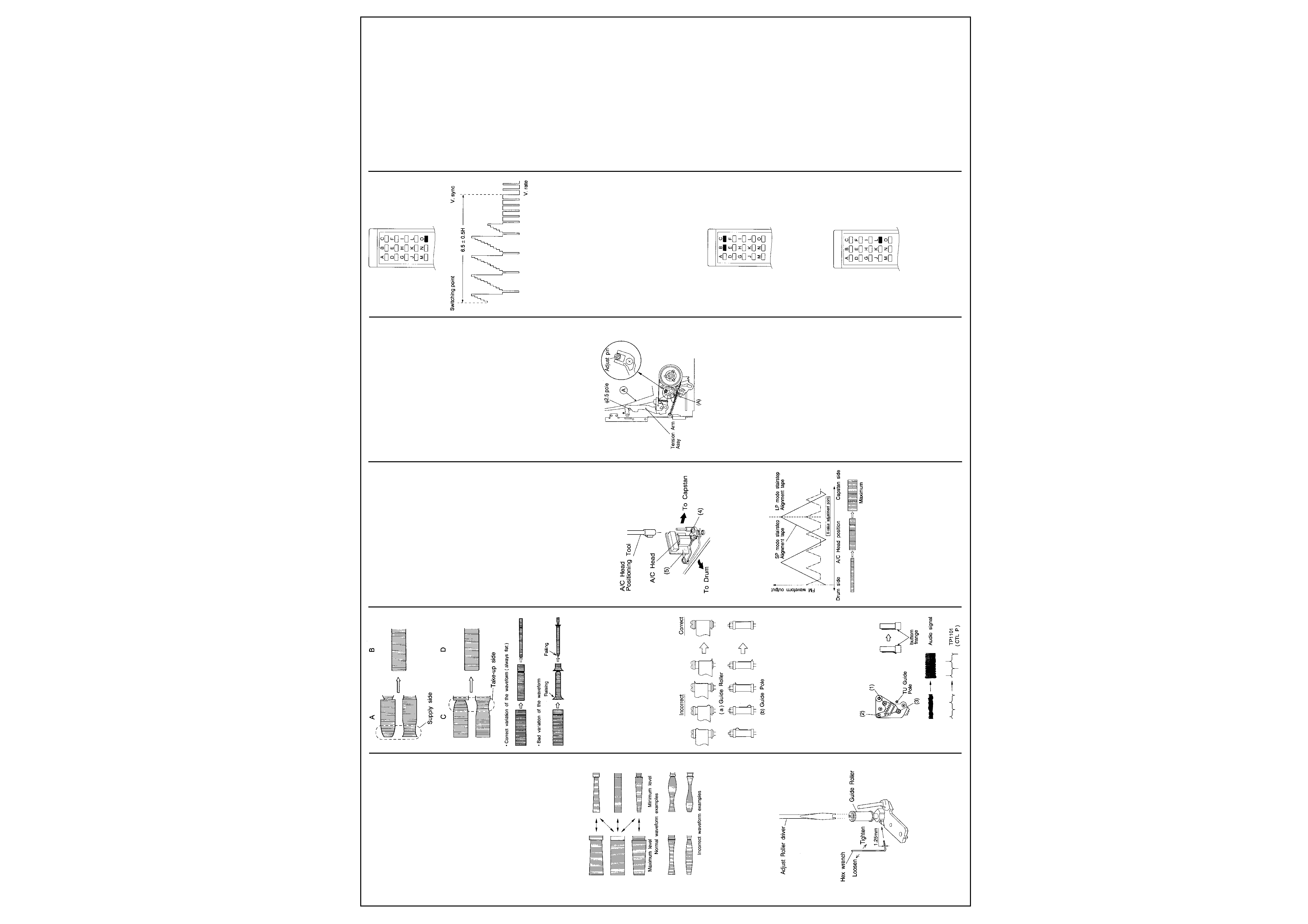
TAPE INTERCHANGEABILITY ADJUSTMENT
NOTE: This adjustment is extremely important.
However, it is normally not required during
routine service. Perform only after replacing
major components (A/C head upper/lower drum
assy, pole base assy, etc). Before using costly
alignment tape use a spare tape and confirm
correct operation of the tape transport.
Tape pattern
1) Connect the oscilloscope to TP106(PB FM)
on the PRE/REC board.Use TP11110.FF) on
the PRE/REC board as a trigger.
2) Playback the SP stairstep portion of the
alignment tape [MHPE].Confirm that the FM
waveform appears as indicated in Fig. 2-7-1.
3) Set the manual tracking position by pressing
the
/ I// button on the remote controller or TV
PROG "-" and "+" buttons simultaneously.
4) Operate the tracking adjustment (press the
TV PROG buttons during playback) and set
for maximum playback FM waveform.
5) By operating the TV PROG buttonvary the
FM waveform from maximum to minimum and
vice versa to confirm that the waveform varies
nearly in a flat shape as shown in Fig.2-7-1.
Fig. 2-7-1
6) When the FM waveform does not remain flat
during this process,first slightly loosen the set
screw located at the bottom of the guide
rollersUsing the guide roller adjustment tool
(Roller driver), adjust the supply and take-up
guide rollers (refer to Fig. 2-7-2) to obtain the
correct waveform as indicated in Fig. 2-7-3.
Fig. 2-7-2
7) By pressing the TV PROG buttons several
times, vary the FM waveform output from
maximum to minimum land vice versa)
graduallyand confirm that the variation
proceeds in flat shape, as shown in Fig. 2-7-3.
Fig. 2-7-3
8) Next playback the LP stairstep portion of the
alignment tape [MHPE-L] and adjust the
tracking control from maximum to minimum
the FM waveform,confirm that FM waveform
variation is always flat.
9) Record the signal and play it back in both of
the SP and LP mode,confirm that the FM
waveform is flat in both mode.
10)After adjustments,tighten the set screw of the
guide rollers.
11)Confirm that the tape wrinking does not occur
at the roller upper or lower limits as indicated
in Fig.2-7-4.
Fig. 2-7-4
A/C head height & azimuth
NOTE: Temporarily set A/C head height as
indicated in Fig. 2-5-4.
Use spare tape to check the transport and
confirm the tape is not scratched or damaged.
1. Tilt
1) Use spare tape and set for playback.
2) Turn screw (3) clockwise to where the tape
curls just slightly at the TU guide pole bottom
flange as shown in Fig. 2-7-5.
Fig. 2-7-5
3) Then slowly turn screw (3) counterclockwise
to where the curling ceases.
2. Height
1) Connect CH-1 of a dual trace oscilloscope to
Audio Out.
2) Connect CH-2 to TP11011 CTL PULSE) of
the Main board assy and use the ALT mode.
3) Playback the SP stairstep portion of the
alignment tape [MHPE].
4) Adjust screws (1) (2) and (3) for maximum
audio output and control pulse level.
3. Azimuth
1) Connect the oscilloscope to Audio Out.
2) Playback the SP stairstep portion of the
alignment tape [MHPE].
3) Adjust screw (2) 50 that the audio output is
both maximum and with minimum fluctuation.
A/C head phase (X-value)
1) Connect the oscilloscope to TP106 (PB FM)
on the PRE/REC board.Use TP111(D.FF) on
the PRE/REC board as a trigger.
2) Playback the SP stairstep portion of the
alignment tape [MHPE].
3) Set the neutral manual tracking position by
pressing the /I// button on the remote
controller or TV PROG "-" and "+" buttons
simultaneously.
4) If adjustment is required,slightly loosen
screws (4) and (5). Set A/C head positioning
tool on the A/C head adjusting boss as
indicated in Fig.2-7-6.
Fig. 2-7-6
5) Turn the tool first to position the NC head fully
toward the capstan. Then gradually return it
toward the drum and stop at the position of
maximum FM waveform output level as
shown in Fig.2-7-7.
Fig. 2-7-7
6) Tighten screw (5). Remove the tool and
tighten screw (4).
7) Eject the SP alighnment tape IMHPE] and
then re-insert the LP alignment tape [MHPE-L].
8) Playback the LP stairstep portion of the
alignment tape [MHPE-L].
9) Set the neutral manual tracking position by
pressing the /I// button on the remote
controller or TV PROG "-" and "+" buttons
simultaneously.
10) Confirm maximum playback FM waveform
output level as shown in Fig.2-7-7.
11) If not maximum,slightly loosen the screws
(4) and (5). Use the tool and adjust the head
position for the nearest maximum point. Then
tighten screws (4) and (5).
LP mode auto tracking
NOTE: Set VCR to the mode A by remote
controller.
1) Connect the oscilloscope to TP106(PB FM)
on the PRE/REC Board. Use TP111(D.FF) on
the PRE/REC board as a trigger.
2) Playback the LP stairstep portion of the
alignment tape [MHPE-L].
3) Confirm the FM waveform of the oscilloscope
screen until auto tracking action is over.
4) Twice press button "D" of the presetting unit
[PTU94008].
5) If the alignment tape ejects automatically,
repeat the A/C head phase adjustment (X-
value).
Tension pole position
1) Set for playback mode using MECHANISM
SERVICE MODE (See SECTION 1 DISAS-
SEMBLY).
2) Slightly loosen the screw (A).
3) Turn the adjust pin so that the tension arm
assy does not touch ø 2.5 pole on the outside.
4) Tighten the screw (A).
5) After adjustment,use the back tension
cassette gauge and set for the playback
mode.
6) Confirm reading of 29 to 46 g·cm.
Fig. 2-7-8
Take-up torque
1) Use the back tension cassette gauge and set
for the playback mode.
2) Confirm reading of 60 to 100 g·cm.
SERVO CIRCUIT
Notes: Unless otherwise specified,all measure-
ment point and adjustment parts are located on
the MAIN BOARD.
Set VCR to the mode A by remote controller.
Use only buttons "0", depressing other buttons
during adjustment may cause adjustment errors.
PB switching point
Signal
· Alignment tape IMHPE]Stairstep
Mode
· PB
Equipment
· Oscilloscope
Measurement point
· J1411-pin 19 (VIDEO OUT)
[TERMINAL BOARD]
Trigger slope (-)
· TP111 (DRUM FF1,[PRE/REC BOARD]
Adjustment tool
· Presetting unit [PTU94008]
Specification
· 6.5
± 0.5H
1) Connect an oscilloscope to J1411-pin 19
(VIDEO OUT) and external trigger from TP111
(negative slope).
2) Playback the stairstep signal of the alignment
tape.
3) Press the "0" button of the presetting unit.
4) Confirm that VCR mode becomes STOP
mode.
Mechanism Adjustments
Cont'd
Fig. 3-2-1 Presetting unit
Fig. 3-2-2 PB switching point
SIow tracking preset
Signal
· Tuner or colour bar
Mode
· SP/LP, REC ¡ PB(SLOW)
Equipment
· TV-Monitor
Adjustment tool
· Presetting unit [PTU94008]
Specification
· Minimum noise
Note: Set VCR to the mode A by remote
controller. Use only buttons "B" and "C",
depressing other buttons during adjustment may
cause adjustment errors.
1) Record a colour bar signal in the SP mode.
2) Playback recorded signal on the FWD slow
mode.
3) Observe the display on the TV monitor and
adjust for optimum noise condition (best
tracking) by depressing "B or "C " buttons of
the presetting unit.
4) Depress the STOP button.
5) Confirm that the bar noise is not visible on the
TV monitor in the slow mode.
Fig.3-2-3 Presetting unit
VIDEO CIRCUIT
Notes: Unless otherwise specified,aIl measure-
ment point and adjustment parts are located on
the MAIN BOARD. Set VCR to the mode A by
remote controller.
Fig.3-3-1 Presetting unit
Auto picture
Signal
· Monoscope
Mode
· REC then PB SP/LP
Adjustment tool
· Presetting unit[PTU94008]
Specification
· STOP mode
1) Record a monoscope signal in the SP mode.
2) Playback the recorded signal.
3) Press the `L' button of the presetting unit
during playback.
4) Confirm that VCR mode becomes STOP
mode.
5) Repeat steps (2) to (4) in the LP mode.
SYSCON CIRCUIT
Notes: Unless otherwise specified,aII measure-
ment point and adjustment parts are located on
the MAIN BOARD. When perform this adjust-
ment, remove the MECHANISM assy.
Timer clock
Signal
· No signal
Mode
· EE
Equipment
· Frequency counter
Measurement point
· TP702 round(SYS.CLK)
Adjustment part
· C701 (TIMER CLOCK)
Specification
· 1024.008
± 0.001 Hz
[976.5549
± 0.0010 used]
1) Connect the frequency counter to TP702
round and GND.
2) Connect the short wire between TP701 round
and Vcc(5V).
3) Short the leads of capacitor C704 once in
order to reset IC701.
4) Disconnect the short wire then connect it
again quickly.
5) Adjust C701 for 1024.008
± 0.001 Hz.
(976.5549
± 0.0010 usec)
TUNER CIRCUIT
Note: Unless otherwise specified, all measure-
ment points and adjustment parts are located on
the IF UNIT.
RF AGC
Signal
· TV broadcasting
Mode
· Tuner
Equipment
· TV monitor
Measurement point
· IF UNIT
Adjustment part
· IF VR
Specification
· Minimum noise
Note: Adjust IF VR (RF AGC) to correct for
excess noise in the picture or when streaks
cross interference occurs due to strong electri-
cal fields.
1) Adjust IF VR to minimize noise or streaks on
the TV screen.
2) Adjust for noisy picture with strong signal.
Then adjust until noise just disappears. Select
other channels to confirm proper pick-up of
channels.
End
5
JVC HR-J635
Mechanical Parts
Item
Part No.
Description
1
PQ46298A-5
TENSION BAND ASSEMBLY
2
5D5T2608Z
SCREW
3
PQ35012-1-3
TENSION ARM LEVER
4
PQM30001-385109
TENSION SPRING
5
PQ46302-1-3
ADJUST PIN
6
PQ463038-7
TENSION ARM ASSEMBLY
7
PQM30017-47
SLIT WASHER
8
PQ46548A
MAIN BRAKE ASSEMBLY (SUPPLY)
9
PQ46306A-3
SUB BRAKE ASSEMBLY (SUPPLY)
10
PQM30001-393
TENSION SPRING
11
PQ46550A
MAIN BRAKE ASSEMBLY (TAKE UP)
12
PQ46309A-4
SUB BRAKE ASSEMBLY (TAKE UP)
13
PQM30001-389102
TENSION SPRING
14
PQ46499A-3
REEL ASSEMBLY (SUPPLY)
15
PQ35014-1-1
SLIT DISK (SUPPLY)
16
PQ35015-1-1
SLIT DISK (TAKE UP)
17
PQM30018-69
SPACER,X2
18
PQM30003-38
BELT(CAPSTAN)
19
PQ46497B-2
PULLEY ASSEMBLY
19A
PQM30002-233
COMPRESION SPRING
19B
PQ46311
SPRING CAP
21
PQ46498A-2
REEL ASSEMBLY (TAKE UP)
Mechanical Parts
Item
Part No.
Description
Mechanical Parts
Item
Part No.
Description
22
PQM30018-69
SPACER
23
PQ46312B-8
IDLER ARM ASSEMBLY
24
PQ46316A-1
CLUTCH UNIT (SUPPLY)
25
PQ46323A-1
CLUTCH UNIT (TAKE UP)
26
PQ46325B-8
GUIDE ARM ASSEMBLY
27
PQ46326-2
TORSION SPRING
28
PQ46327A
PINCH ROLLER ARM ASSEMBLY
29
PQM30017-24
SLIT WASHER,P LEVER
30
PEHE0182
AUDIO CONTROL HEAD
31
PQ35206-1-3
HEAD BASE
32
PQ43687A
SPECIAL SCREW,X3
33
PQM30002-192
COMPRESSION SPRING,X3
34
SDSP2604Z
SCREW,X2
35
PQ46595A
POLE BASE ASSEMBLY (SUPPLY)
36
PQ46597A
POLE BASE ASSEMBLY (TAKE UP)
37
PQ46332A-3
LOADING ARM ASSEMBLY (SUPPLY)
38
PQ46337A-6
LOADING ARM ASSEMBLY (TAKE UP
39
PQ11657-1-9
GUIDE RAIL
40
SPST2608Z
SCREW,X4
41
SDST2612Z
SCREW
42
PQ21684-1-3
CONTROL CAM
43
PQ35138-1-2
CONTROL BRACKET
45
PQ11658-1-12
CONTROL PLATE
46
PQM30017-8
SLIT WASHER
47
PQ21685-2-9
PINCH PLATE
48
SPST2606Z
SCREW,X2
49
SPSF2608M
SCREW
50
PQ46342B-10
LEVER ASSEMBLY
51
PQM30017-8
SLIT WASHER
52
PQ35083-1 -8
REEL BRACKET
53
PQM30017-51
SLIT WASHERX2
54
Q03093-830
WASHER
55
PQ35026-1-7
IDLER LEVER
56
PQ11659-1-11
SLIDE PLATE
57
PQ46344A-2
CHANGE LEVER ASSEMBLY
58
PQ21686-1-3
TAKE UP LEVER ASSEMBLY
59
PQ46345-1-2
TAKE UP HEAD
60
PQM30001-387106
TENSION SPRING
61
PU60628-3-2
LOADING MOTOR
62
SPSP3003Z
SCREW,X2
63
PW30101-80AJ632
WIRE
64
PQM30003-39
BELT
65
PQ46395B
WORM GEAR ASSEMBLY
66
PQ21699
WORM BEARING
67
SPST2606Z
SCREW
68
PU61487-2
CAPSTAN MOTOR
69
PQ46347F-15
SUB DECK ASSEMBLY
70
SPSG2608Z
SCREW,X3
71
PQ46356C-3
CAPSTAN BRAKE ASSEMBLY
72
SPST2606Z
SCREW,X2
73
PQM30001-384101
TENSION SPRING,CAPSTAN BRAKE
74
PQ46353A-2
CHANGE ARM ASSEMBLY
75
PQ46354
CHANGE GEAR
76
PQM30001-386
TENSION SPRING
77
PQM30003-40
BELT
78
PQ46355
CASSETTE GEAR
79
PQ35030-1-5
LID GUIDE
80
PQ21689-2
LED PRISM
81
PEHE0237
FULL ERASE HEAD
82
SDST2610Z
SCREW
83
PU61432-1-1
ROTARY ENCODER
86
PQ43546-1-2
MOTOR PULLEY
87
PQ35217-1-2
CONTROL BRACKET 2
92
SDST2608Z
SCREW
93
SDST2608Z
SCREW
99
PQ21680D-18
MAIN DECK ASSEMBLY
Exploded Parts
View
Remote Control Diagram