SERVICE MANUAL
SPECIFICATIONS AND PARTS ARE SUBJECT TO CHANGE FOR IMPROVEMENT
Digital Media Division
DVD VIDEO CAMERA/RECORDER
2003
April
SM7304
DZMV380E
DZMV380EAU
DZMV380ESW
DZMV380ESWH
DZMV380EUK
MultiMediaCard TM

Table of Contents
1 Safety Precaution for Repair ............. 1-1
1-1 Cautions ................................................... 1-1
1-2 Notes When Using Service Manual .......... 1-2
1-2-1 Value units used in parts list .................. 1-2
1-2-2 Values in schematic diagrams ............... 1-2
1-2-3 Identifications of sides A/B in
circuit board diagrams ........................... 1-2
1-2-4 Table for indexing locations of parts ....... 1-3
1-3 Electrostatic Protection Measures ............ 1-4
1-3-1 Grounding for prevention of
electrostatic damage ............................. 1-4
1-3-2 Cautions when handling
optical pickup ......................................... 1-4
1-4 Lead-Free Solder ...................................... 1-5
1-4-1 Characteristics of lead-free solder ......... 1-5
1-4-2 Solder for servicing ................................ 1-5
1-4-3 Soldering iron for servicing .................... 1-5
2 General Description ........................... 2-1
2-1 Overview .................................................. 2-1
2-1-1 Servicing method ................................... 2-2
2-2 Features ................................................... 2-3
2-3 Specifications ........................................... 2-4
2-4 Major Differences from
Previous Models ....................................... 2-6
2-5 List of Functions ....................................... 2-7
2-6 Compatibility of Recorded Discs ............... 2-9
2-7 Name of Parts .......................................... 2-10
2-8 Inserting Disc ........................................... 2-12
2-9 List of Abbreviations and Terms for
DVD Video Camera/Recorders ................. 2-14
3 Description of Operation ................... 3-1
3-1 Description of Mechanism ........................ 3-1
3-2 Description of Newly Adopted
Technology ............................................... 3-3
3-2-1 Overview of SD memory card and
MultiMediaCard ..................................... 3-3
3-2-2 Standards for photo
recording on card .................................. 3-4
3-2-3 Software disc-protect function ............... 3-5
4 Troubleshooting .................................. 4-1
4-1 Procedure for Troubleshooting .................. 4-1
4-2 System Resetting/Resetting
Camera Functions .................................... 4-2
4-2-1 List of setting items to be reset .............. 4-2
4-2-2 System reset procedure ........................ 4-3
4-2-3 Procedure for resetting
camera functions ................................... 4-3
4-3 Problem Guide .......................................... 4-4
4-4 Messages and Troubleshooting ................ 4-10
4-5 Self-Diagnosis Function and
Troubleshooting ........................................ 4-20
4-5-1 Message displayed by
self-diagnosis function ........................... 4-20
4-5-2 Error codes stored in flash memory ....... 4-22
4-5-3 Major error codes and
troubleshooting ...................................... 4-23
4-6 Checking Versions of Firmware and
Updating ................................................... 4-25
4-6-1 Checking firmware versions ................... 4-25
4-6-2 Updating firmware ................................. 4-26
4-7 Trouble Diagnosis ..................................... 4-28
4-7-1 Selecting service position ...................... 4-28
4-7-2 Disassembly/reassembly for enabling
service position ..................................... 4-29
4-7-3 Trouble diagnosis table .......................... 4-32
4-8 Procedure for Removing Disc from
Faulty DZ-MV350E ................................... 4-35
4-8-1 Item to be checked ................................ 4-35
4-8-2 How to remove disc ............................... 4-35
4-9 Special Functions ..................................... 4-37
4-9-1 Forced formatting of DVD-RAM disc ...... 4-37
5 Disassembly and Reassembly .......... 5-1
5-1 Preparations for Disassembly ................... 5-1
5-2 Order of Disassembly ............................... 5-1
5-3 Disassembly ............................................. 5-3
(1) Adjustment Cover .................................. 5-3
(2) Hood, Filter Piece and Lens Cover ....... 5-3
(3) Eyecup,
SAF Circuit Board and L Block ............. 5-4
i

(4) Front Block, FAF Circuit Board and
R Block .................................................. 5-5
(5) L Cover, L Case and LCD Block ............ 5-6
(6) Microphone, Microphone Cover,
Jack Cover, Front Case and
FRT Circuit Board .................................. 5-6
(7) LCD Case U, MR Circuit Board
and Fulcrum Block ................................. 5-7
(8) Disc Cover ...................................... 5-8
(9) USB Circuit Board, Rear Cover,
and Hand Strap .................................... 5-9
(10) SHE Circuit Board, Accesory Shoe
(12) Camera Block ...................................... 5-12
(13) LCD Circuit Board, Backlight, LCD Unit
and LCD Case ....................................... 5-13
(14) Link Bracket, Drive Block and R Case .. 5-14
(15) Fulcrum Cover U and
Fulcrum Cover B .................................. 5-15
(16) GYR Circuit Board, Lens Frame, Lens
(17) Loader, DRF Circuit Board,
Disc Drive Unit, and Lock Unit .............. 5-16
6-2 Setups for Adjustment............................... 6-11
6-3 List of Adjustment Items............................ 6-18
6-4 Adjustment Procedure............................... 6-21
7 Exploded View and Parts List ............ 7-1
7-1 Exploded Views ........................................ 7-1
7-1-1 Main section .......................................... 7-1
7-1-2 LCD Block Section ................................. 7-2
7-2 Replacement Parts List ............................ 7-3
7-2-1 Mechanical parts list .............................. 7-3
7-2-2 Electrical parts list ................................. 7-4
Schematic, Circuit Board and Block
Diagrams .................................................... 1
1 Wiring Diagram .............................................. 1
2 Schematic Diagrams ..................................... 2
2-2 FRT Schematic Diagram ........................... 3
2-3 FAF Schematic Diagram ............................ 3
2-4 SAF Schematic Diagram ........................... 3
2-5 GYR Schematic Diagram .......................... 4
2-6 SHE Schematic Diagram ........................... 4
2-7 Board to Board [AEL]
Schematic Diagram ................................... 5
2-8 Lens Drive [AEL] Schematic Diagram ........ 6
2-9 Audio [AEL] Schematic Diagram ............... 7
2-10 EVF [AEL] Schematic Diagram .................. 8
2-11 LCD Schematic Diagram ........................... 9
2-12 MR Schematic Diagram ............................. 10
2-13 USB Schematic Diagram ........................... 10
2-14 DRF Schematic Diagram ........................... 10
2-15 IC Block Diagrams ..................................... 11
3 Circuit Board Diagram ................................... 13
3-2 SHE Circuit Board Diagram ....................... 13
3-3 FRT Circuit Board Diagram ....................... 14
3-4 FAF, SAF Circuit Board Diagram .............. 14
3-5 GYR Circuit Board Diagrams ..................... 15
3-6 DRF Circuit Board Diagram ....................... 15
3-7 MR Circuit Board Diagram ......................... 16
3-8 USB Circuit Board Diagram ....................... 16
3-9 AEL Circuit Board Diagram ........................ 17
3-10 LCD Circuit Board Diagram ....................... 18
3-11 MAN Circuit Board Diagram ....................... 19
3-15 Identification of Parts Location .................... 22
4 Block Diagrams .............................................. 23
4-1 Video/Audio Signal Process Section ........... 23
4-2 Disc Drive Section ...................................... 24
4-3 Power-1 ...................................................... 25
4-4 Power-2 ...................................................... 26
ii
Information of MAN, DRV, SID and HDM
Circuit Boards
During servicing, replace the entire MAN
circuit board and the entire disc drive unit,
including the DRV, SID and HDM circuit
boards.
6-1 Creating Reference Data.......................... 6-1
6 Adjustment........................................... 6-1
and EVF Unit ...................................... 5-10
(11) AEL and MAN Circuit Boards ............... 5-11
Unit, SEN Circuit Board and Sensor .... 5-15
7-1-3 Camera Block Section........................... 7-2
2-1 SEN Schematic Diagram ............................ 2
3-1 SEN Circuit Board Diagram ....................... 13
3-12 DRV Circuit Board Diagram ....................... 20
3-13 SID Circuit Board Diagram ......................... 21
3-14 HDM Circuit Board Diagram ......................... 21
1 - 1
Safety Precaution for Repair
1
CAUTION (COLOR LCD)
LCD display; the liquid crystal display (LCD) panel is mode by highly precise technology.
More than 99.99% of its picture elements (pixels) are effective, but some (less than 0.01%) may appear
as colored bright dots. This mode not indicate a fault as the LCD panel stretches the limits of current
technology.
CLASS 1
LASER PROCTECT
CAUTION
This product contains a laser diode of
higher class than 1. To ensure contin-
ued safety, do not remove any covers
or attempt to gain access to the in-
side of the product. Refer all servicing
to qualified personnel.
Many electrical and mechanical parts have special safety-related characteristics. These are often not
evident from visual inspection nor can the protection afforded by them necessarily be obtained by using
replacement components rated for a higher voltage, wattage, etc. Replacement parts which have these
special safety characteristics are identified in this Service Manual. Electrical components having such
features are identified by marking with a
on the schematics and the parts list in this Service Manual.
The use of a substitute replacement component which does not have the same safety characteristics as
the HITACHI recommended replacement one, shown in the parts list in this Service Manual, may create
shock, fire, or other hazards. Product safety is continuously under review and new instructions are issued
from time to time. For the latest information, always consult the current HITACHI Service Manual. A
subscription to, or additional copies for, HITACHI Service Manual may be obtained at a nominal charge
from HITACHI SALES CORPORATION.
PRODUCT SAFETY NOTICE
Lithium battery; danger of explosion if battery is incorrectly replaced. Replace only with the same or
equivalent type recommended by the equipment manufacturer. Discard used batteries according to
manufacturer's instructions.
When replacing the lithium battery it is important to use the same type and connect it correctly.
WARNING:
Lithium batteries contain dangerous chemicals.
Handle and dispose of with great care.
Do not throw in a fire.
Do not short circuit it.
For disposal place in a plastic bag and put in waste bin.
CAUTION
CAUTION
BLE
VISI
AND INVISIBLE
LASER RADIATION WHEN OPEN.
AVOID EXPOSURE TO BEAM.
CAUTION
There is a high-voltage section inside the DVD video
camera/recorder: When repairing or inspecting it, take
great care to prevent electric shock: Use an isolating
transformer, wear gloves, etc.
1-1 Cautions
1 - 2
1-2 Notes When Using Service Manual
The following shows the contents to be noted when using service manual:
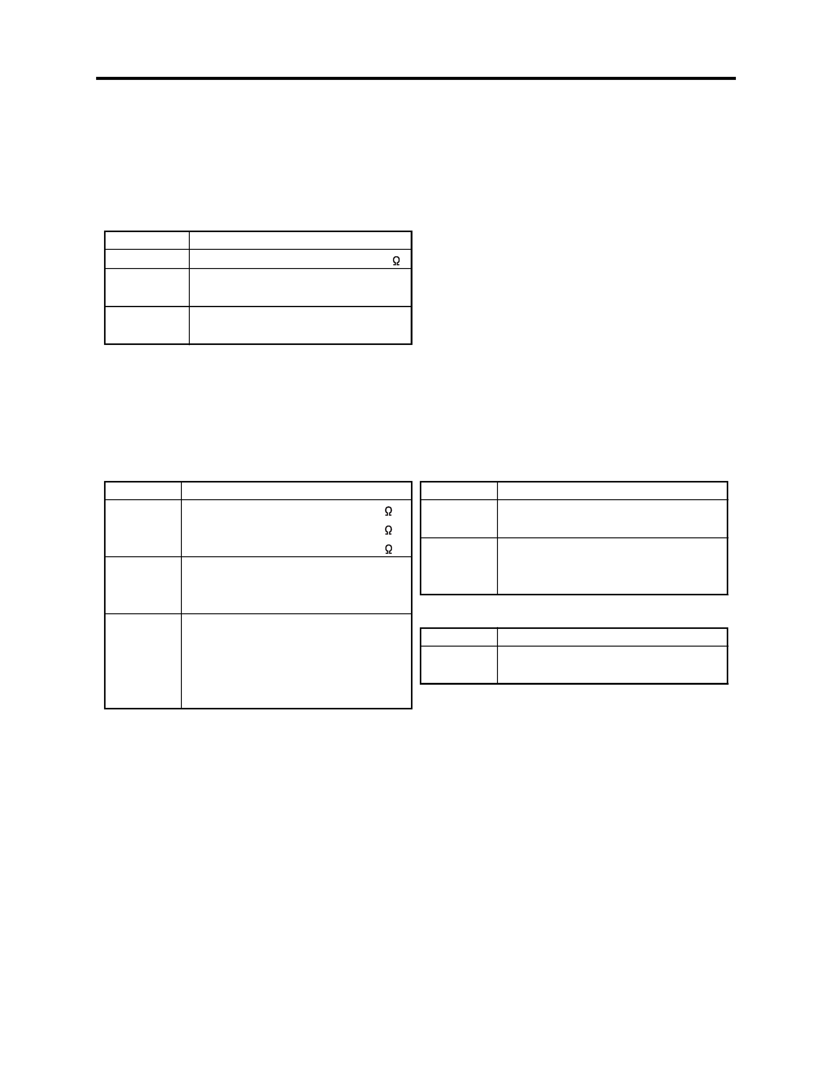
1-2-1 Value units used in parts list
Certain symbols are indicated below for value units of resistors, capacitors and coils in parts list. When you read
them note the following regular indications:
1-2-2 Values in schematic diagrams
The values, dielectric strength (power capacitance) and tolerances of the resistors (excluding
variable resistors) and capacitors are indicated in the schematic diagrams using abbreviations.
Indication in list
Regular indication
KOHM ........................................... k
UF ................................................ µF
PF ................................................ pF
UH ................................................ µH
MH ............................................... mH
Parts
Resistor
Capacitor
Coil
1-2-3 Identifications of sides A/B in circuit board diagrams
1) Board having a pattern on one side and parts on both sides.
Side A: Shows discrete parts, viewed from the pattern side.
Side B: Shows leadless parts, viewed from the pattern side.
2) Board having patterns on both sides and parts on both sides.
Side A: Shows parts and patterns which can be seen when the case is opened.
Side B: Shows parts and the pattern on the back of side A.
Item
Value
Tolerance
Power
capacitance
Indication
No indication ...................................
K ................................................... k
M .................................................. M
No indication ............................. ±5%
(All tolerances other than ±5% are
indicated in schematic diagrams)
No indication ............................ 1/8W
(1/16W for leadless resistors without
indication)
All capacitances other than the above
are indicated in schematic diagrams.
Item
Value
Dielectric
strength
Indication
No indication ................................. µF
P ................................................... pF
No indication .............................. 50V
(All dielectric strengths other than 50V
are indicated in schematic diagrams)
Item
Value
Indication
µ .................................................... µH
m .................................................. mH
[Resistors]
[Capacitors]
[Coils]
Safety Precaution for Repair > Notes When Using Service Manual