SERVICE MANUAL
Digital Media Division
DVD PLAYER & VIDEO CASSETTE RECORDER
SPECIFICATIONS AND PARTS ARE SUBJECT TO CHANGE FOR IMPROVEMENT
No. 9208E
DVPF2E
DVPF2EUK
July
2002
PA L
OPEN/
CLOSE
DVD
VCR
TIMER SET
TIMER SET
ST
STANDBY
ANDBY
CST
CST.IN
.IN
OUTPUT
OUTPUT
CHANNEL
CHANNEL
VIDEO IN
VIDEO IN
L
(mono)
(mono)
R
AUDIO IN
UDIO IN
OPEN/
CLOSE
DVD
VCR
TIMER SET
TIMER SET
ST
STANDBY
ANDBY
CST
CST.IN
.IN
OUTPUT
OUTPUT
CHANNEL
CHANNEL
VIDEO IN
VIDEO IN
L
(mono)
(mono)
R
AUDIO IN
UDIO IN
CONTENTS
SPECIFICATIONS. . . . . . . . . . . . . . . . . . . . . . . . . . . .E1-1-1
LASER BEAM SAFETY PRECAUTIONS. . . . . . . . . .E1-2-1
IMPORTANT SAFETY PRECAUTIONS . . . . . . . . . . .E1-3-1
Product Safety Notice . . . . . . . . . . . . . . . . . . . . . . . .E1-3-1
Precautions during Servicing. . . . . . . . . . . . . . . . . . .E1-3-1
Safety Check after Servicing . . . . . . . . . . . . . . . . . . .E1-3-2
STANDARD NOTES FOR SERVICING . . . . . . . . . . .E1-4-1
Circuit Board Indications . . . . . . . . . . . . . . . . . . . . . .E1-4-1
Instructions for Connectors . . . . . . . . . . . . . . . . . . . .E1-4-1
How to Remove/Install Flat Pack-IC . . . . . . . . . . . . .E1-4-1
Instructions for Handling Semi-conductors . . . . . . . .E1-4-3
PREPARATION FOR SERVICING . . . . . . . . . . . . . . .E1-5-1
How to Enter the Service Mode. . . . . . . . . . . . . . . . .E1-5-1
OPERATING CONTROLS AND FUNCTIONS . . . . . .E1-6-1
FIRMWARE RENEWAL MODE . . . . . . . . . . . . . . . . .E1-7-1
TROUBLESHOOTING . . . . . . . . . . . . . . . . . . . . . . . .E1-8-1
CABINET DISASSEMBLY INSTRUCTIONS . . . . . . .E2-1-1
1. Disassembly Flowchart . . . . . . . . . . . . . . . . . . . . .E2-1-1
2. Disassembly Method . . . . . . . . . . . . . . . . . . . . . . .E2-1-1
DISASSEMBLY/ASSEMBLY PROCEDURES OF
DECK MECHANISM . . . . . . . . . . . . . . . . . . . . . . . . .E2-2-1
ALIGNMENT PROCEDURES OF MECHANISM . . . .E2-3-1
ELECTRICAL ADJUSTMENT INSTRUCTIONS . . . .E2-4-1
Test Equipment Required . . . . . . . . . . . . . . . . . . . . .E2-4-1
Head Switching Position Adjustment. . . . . . . . . . . . .E2-4-1
FIXTURE AND TAPE FOR ADJUSTMENT . . . . . . . .E2-5-1
How To Use The Fixtures And Tape . . . . . . . . . . . . .E2-5-1
MECHANICAL ALIGNMENT PROCEDURES . . . . . .E2-6-1
Service Information . . . . . . . . . . . . . . . . . . . . . . . . . .E2-6-1
1. Tape Interchangeability Alignment. . . . . . . . . . . . .E2-6-2
1-A.Preliminary/Final Checking and
Alignment of Tape Path . . . . . . . . . . . . . . . . . .E2-6-3
1-B.X Value Alignment . . . . . . . . . . . . . . . . . . . . . . .E2-6-3
1-C.Checking/Adjustment of Envelope Waveform . .E2-6-4
1-D.Azimuth Alignment of
Audio/Control/Erase Head . . . . . . . . . . . . . . . .E2-6-4
STANDARD MAINTENANCE . . . . . . . . . . . . . . . . . . .E2-7-1
Service Schedule of Components . . . . . . . . . . . . . . .E2-7-1
Cleaning . . . . . . . . . . . . . . . . . . . . . . . . . . . . . . . . . .E2-7-2
EXPLODED VIEWS . . . . . . . . . . . . . . . . . . . . . . . . . . . 3-1-1
Cabinet . . . . . . . . . . . . . . . . . . . . . . . . . . . . . . . . . . . . 3-1-1
Deck Mechanism View 1 . . . . . . . . . . . . . . . . . . . . . . . 3-1-2
Deck Mechanism View 2 . . . . . . . . . . . . . . . . . . . . . . . 3-1-2
Deck Mechanism View 3 . . . . . . . . . . . . . . . . . . . . . . . 3-1-3
REPLACEMENT PARTS LIST . . . . . . . . . . . . . . . . . . . 3-2-1
Mechanical Parts List . . . . . . . . . . . . . . . . . . . . . . . . . 3-2-1
Electrical Parts List . . . . . . . . . . . . . . . . . . . . . . . . . . . 3-2-3
SCHEMATIC DIAGRAMS/CBA'S AND
TEST POINTS. . . . . . . . . . . . . . . . . . . . . . . . . . . . . . . 4-1-1
<VCR SECTION>
Wiring Diagram . . . . . . . . . . . . . . . . . . . . . . . . . . . . . . 4-1-3
Main 1/8 Schematic Diagram . . . . . . . . . . . . . . . . . . . 4-1-4
Main 2/8 Schematic Diagram . . . . . . . . . . . . . . . . . . . 4-1-5
Main 3/8 Schematic Diagram . . . . . . . . . . . . . . . . . . . 4-1-6
Main 4/8 Schematic Diagram . . . . . . . . . . . . . . . . . . . 4-1-7
Main 5/8 Schematic Diagram . . . . . . . . . . . . . . . . . . . 4-1-8
Main 6/8 Schematic Diagram . . . . . . . . . . . . . . . . . . . 4-1-9
Waveforms . . . . . . . . . . . . . . . . . . . . . . . . . . . . . . . . 4-1-10
Main 7/8 Schematic Diagram . . . . . . . . . . . . . . . . . . 4-1-11
Main 8/8 Schematic Diagram . . . . . . . . . . . . . . . . . . 4-1-12
Power Supply Schematic Diagram . . . . . . . . . . . . . . 4-1-13
Function Schematic Diagram . . . . . . . . . . . . . . . . . . 4-1-14
Front Jack Schematic Diagram . . . . . . . . . . . . . . . . . 4-1-15
AFV Schematic Diagram . . . . . . . . . . . . . . . . . . . . . . 4-1-16
Main CBA Top View . . . . . . . . . . . . . . . . . . . . . . . . . 4-1-17
Main CBA Bottom View . . . . . . . . . . . . . . . . . . . . . . . 4-1-18
Power Supply CBA Top/Bottom View . . . . . . . . . . . . 4-1-19
Function CBA Top/Bottom View . . . . . . . . . . . . . . . . 4-1-20
Front Jack CBA Top/Bottom View. . . . . . . . . . . . . . . 4-1-21
AFV CBA Top/Bottom View. . . . . . . . . . . . . . . . . . . . 4-1-22
Junction-A CBA Top/Bottom View. . . . . . . . . . . . . . . 4-1-22
Junction-B CBA Top/Bottom View. . . . . . . . . . . . . . . 4-1-22
<DVD SECTION>
Wiring Diagram . . . . . . . . . . . . . . . . . . . . . . . . . . . . . 4-1-23
DVD Main 1/4 Schematic Diagram . . . . . . . . . . . . . . 4-1-24
DVD Main 2/4 Schematic Diagram . . . . . . . . . . . . . . 4-1-25
DVD Main 3/4 Schematic Diagram . . . . . . . . . . . . . . 4-1-26
DVD Main 4/4 Schematic Diagram . . . . . . . . . . . . . . 4-1-27
BLOCK DIAGRAMS . . . . . . . . . . . . . . . . . . . . . . . . . . . 4-2-1
<VCR SECTION>
Servo/System Control Block Diagram . . . . . . . . . . . . . 4-2-1
Video Block Diagram. . . . . . . . . . . . . . . . . . . . . . . . . . 4-2-2
Audio Block Diagram. . . . . . . . . . . . . . . . . . . . . . . . . . 4-2-3
Hi-Fi Audio Block Diagram . . . . . . . . . . . . . . . . . . . . . 4-2-4
Power Supply Block Diagram . . . . . . . . . . . . . . . . . . . 4-2-5
<DVD SECTION>
DVD System Control Block Diagram. . . . . . . . . . . . . . 4-2-6
RF Signal Process/Servo Block Diagram . . . . . . . . . . 4-2-7
DVD Signal Process Block Diagram . . . . . . . . . . . . . . 4-2-8
DVD Video Block Diagram . . . . . . . . . . . . . . . . . . . . . 4-2-9
DVD Audio Block Diagram . . . . . . . . . . . . . . . . . . . . 4-2-10
SYSTEM CONTROL TIMING CHARTS . . . . . . . . . . . . 4-3-1
IC PIN FUNCTION DESCRIPTIONS . . . . . . . . . . . . . . 4-4-1
LEAD IDENTIFICATIONS. . . . . . . . . . . . . . . . . . . . . . . 4-5-1
CHAPTER 1 GENERAL INFORMATION
CHAPTER 2 DISASSEMBLY AND ADJUSTMENT
CHAPTER 3 EXPLODED VIEWS AND PARTS LIST
CHAPTER 4
SCHEMATIC AND BLOCK DIAGRAMS/
CBA'S

E1-1-1
SPECIFICATIONS
Manufactured under license from Dolby Laboratories. "Dolby" and
the double-D symbol are trademarks of Dolby Laboratories.
"DTS" and "DTS Digital Out" are trademarks of Digital Theater Systems Inc.
CHAPTER 1
GENERAL INFORMATION
Product type:
DVD/VCR player with Video Cassette Recorder
Discs:
DVD video
Audio CD
Video Cassette tape
Converter output:
UHF Channel 22 to 69.
Power source:
220-240V +/- 10%, 50Hz +/- 0.5%
Power consumption:
30 W (standby: 5.7 W)
Operating temperature:
5°C to 40°C
Dimensions:
W 17-1/8" (435 mm)
H 4" (99 mm)
D 10-1/2" (266 mm)
Weight:
8.8 lbs (4 kg)
Designs and specifications are subject to change without notice.
E1-2-1
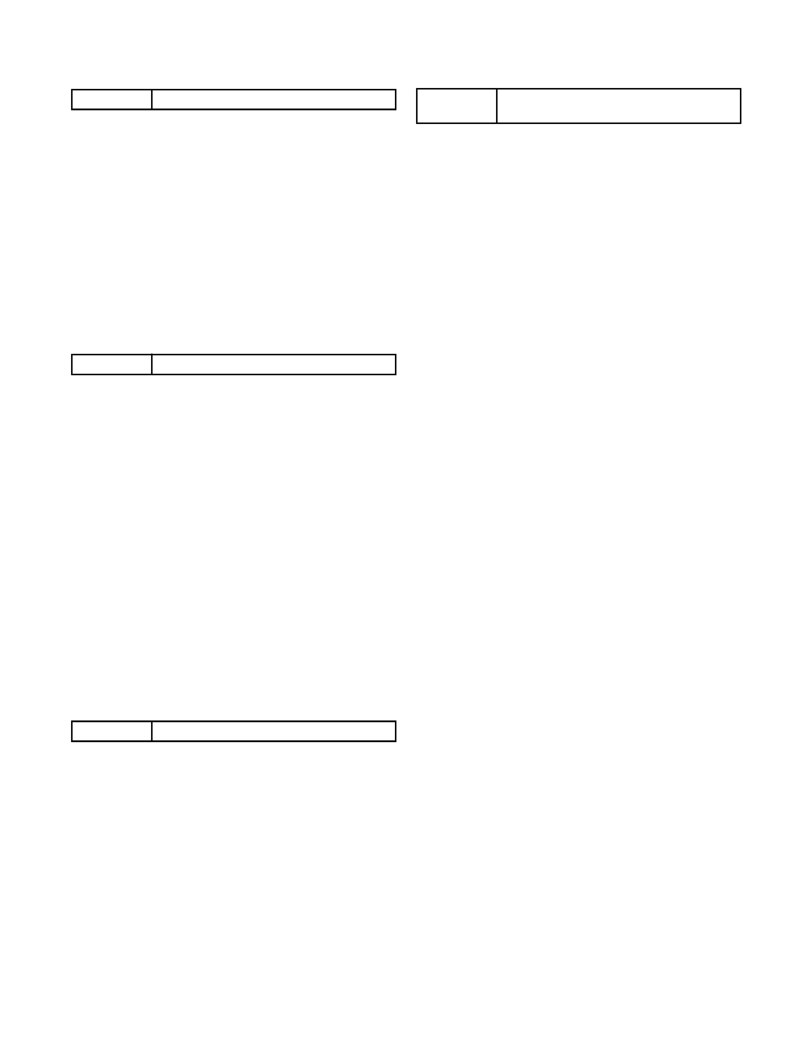
Drive Mecha Assembly
Laser Beam Radiation
Laser Pickup
Turntable
CAUTION - VISIBLE LASER
RADIATION WHEN OPEN AND
INTERLOCK DEFEATED.
AVOID EXPOSURE TO BEAM.
LASER BEAM SAFETY PRECAUTIONS
This DVD player uses a pickup that emits a laser beam.
The laser beam is emitted from the location shown in the figure. When checking the laser diode, be sure to keep
your eyes at least 30cm away from the pickup lens when the diode is turned on. Do not look directly at the laser
beam.
Caution: Use of controls and adjustments, or doing procedures other than those specified herein, may result in
hazardous radiation exposure.
Do not look directly at the laser beam coming
from the pickup or allow it to strike against
your skin.
Location: Inside Top of DVD mechanism.

E1-3-1
IMPORTANT SAFETY PRECAUTIONS
Product Safety Notice
Some electrical and mechanical parts have special
safety-related characteristics which are often not evi-
dent from visual inspection, nor can the protection
they give necessarily be obtained by replacing them
with components rated for higher voltage, wattage,
etc. Parts that have special safety characteristics are
identified by a ! on schematics and in parts lists. Use
of a substitute replacement that does not have the
same safety characteristics as the recommended
replacement part might create shock, fire, and/or other
hazards. The Product's Safety is under review contin-
uously and new instructions are issued whenever
appropriate. Prior to shipment from the factory, our
products are carefully inspected to confirm with the
recognized product safety and electrical codes of the
countries in which they are to be sold. However, in
order to maintain such compliance, it is equally impor-
tant to implement the following precautions when a set
is being serviced.
Precautions during Servicing
A. Parts identified by the ! symbol are critical for
safety. Replace only with part number specified.
B. In addition to safety, other parts and assemblies
are specified for conformance with regulations
applying to spurious radiation. These must also be
replaced only with specified replacements.
Examples: RF converters, RF cables, noise block-
ing capacitors, and noise blocking filters, etc.
C. Use specified internal wiring. Note especially:
1)Wires covered with PVC tubing
2)Double insulated wires
3)High voltage leads
D. Use specified insulating materials for hazardous
live parts. Note especially:
1)Insulation tape
2)PVC tubing
3)Spacers
4)Insulators for transistors
E. When replacing AC primary side components
(transformers, power cord, etc.), wrap ends of
wires securely about the terminals before solder-
ing.
F. Observe that the wires do not contact heat produc-
ing parts (heatsinks, oxide metal film resistors, fus-
ible resistors, etc.).
G. Check that replaced wires do not contact sharp
edges or pointed parts.
H. When a power cord has been replaced, check that
5 - 6 kg of force in any direction will not loosen it.
I. Also check areas surrounding repaired locations.
J. Be careful that foreign objects (screws, solder
droplets, etc.) do not remain inside the set.
K. Crimp type wire connector
The power transformer uses crimp type connectors
which connect the power cord and the primary side
of the transformer. When replacing the transformer,
follow these steps carefully and precisely to pre-
vent shock hazards.
Replacement procedure
1)Remove the old connector by cutting the wires at a
point close to the connector.
Important: Do not re-use a connector. (Discard it.)
2)Strip about 15 mm of the insulation from the ends
of the wires. If the wires are stranded, twist the
strands to avoid frayed conductors.
3)Align the lengths of the wires to be connected.
Insert the wires fully into the connector.
4)Use a crimping tool to crimp the metal sleeve at its
center. Be sure to crimp fully to the complete clo-
sure of the tool.
L. When connecting or disconnecting the internal con-
nectors, first, disconnect the AC plug from the AC
outlet.