
HITACHI
No. 0125
CV80D BS
CV80DC BS
CV80DP BS
SERVICE MANUAL
CONTENTS
1. ATTACHMENTS
2
2. FEATURES
2
3. REPLACEMENT INSTRUCTIONS
2
4. CARE OF AIR FILTER
5
5. FINAL TEST
6
6. GENERAL INSTRUCTIONS FOR
OPERATION AND MAINTENANCE
7
7. PARTS LIST
8
8. CONSTRUCTION DIAGRAM AND
CONNECTION DIAGRAM
17
NOVEMBER
2000
Home Appliances Division
VACUUM CLEANER
SPECIFICATIONS AND PARTS ARE SUBJECT TO CHANGE TO IMPROVEMENT
SPECIFICATIONS
Rated voltage
:AC230-240V,50Hz
Rated input
:1200-1300W
Motor
:Commutator motor
Fan
:Turbo type 1 stage
Speed
:30,000rpm
Insulation class of materials
:Class E
Maximum air flow(without attachment)
:1.6m3/min(57 cu.ft/min)
Maximum static pressure
:1,600mmAq(63 in Aq)
Weight
:6.7kg(14.8lbs)(CV-80D,DC,DP)
Dimensions
:322mm(L)x320mm(W)x1070mm(H)
-2-
1 . ATTACHMENTS
Handle
1
Hose assembly
1
Extension pipes
2
Dusting brush
1
Crevice nozzle
1
Paper bag filter
2
Fabric nozzle
1
(CV-80DP only)
2 . FEATURES
(1) 1500W motor power quiet suction system
(2) Power control [CV-80DC,DP]
(3) Automatic height control
(4) Front edge cleaning
(5) Brushed edge cleaning (Both side)
(6) Large capacity dust bag (6L)
(7) Dust bag full indicator
(8) Built in tools
3 . REPLACEMENT INSTRUCTIONS
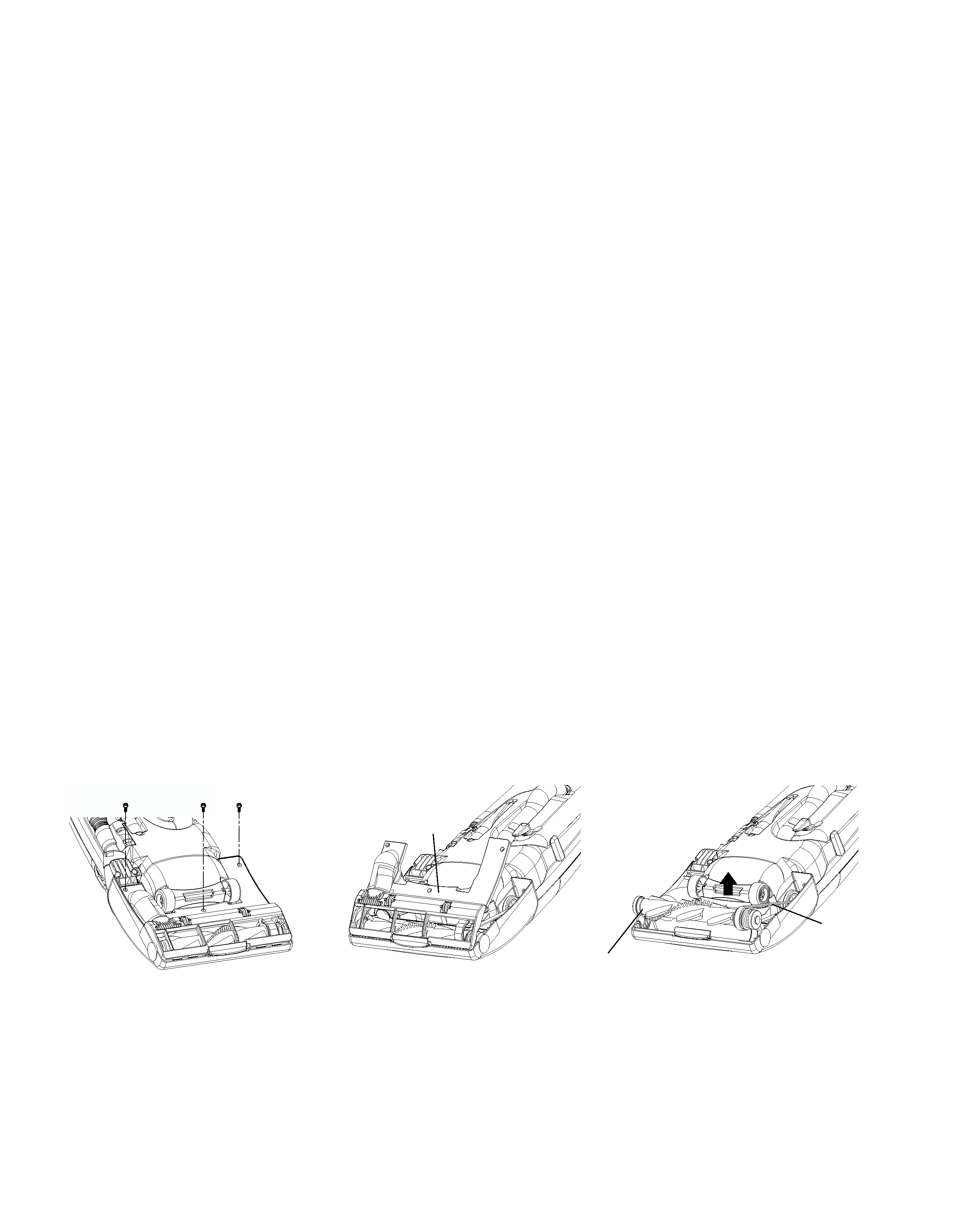
3.1 HOW TO DISMANTLE BELT COVER AND NOZZLE COVER
(1) Disconnect the plug of the cleaner from the electrical outlet.
(2) Turn the cleaner over. Take off the three p tite screws 4
20(32)(33)(33).
(3) Remove the belt cover(42)(43)(43).
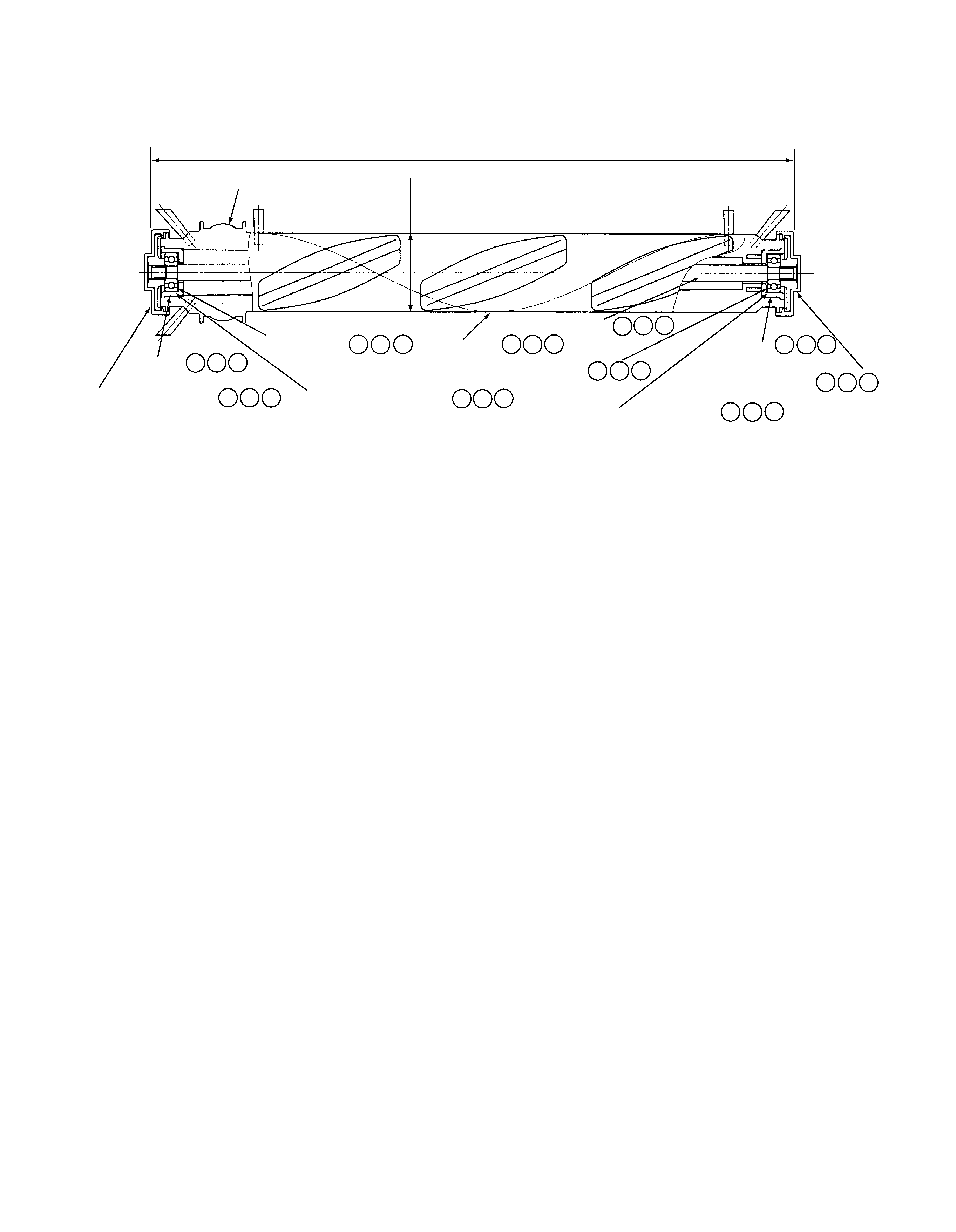
(4) To disassemble the rotary brush assembly,grasp the rubber end covers and turn them counterclockwise until one
of the end caps comes off. Separate the rotary brush(54)(55)(55) from the other parts.
In case you need to remove the remaining end cap,hold the midle of the B shaft (59)(60)(60) by pliers and turn the
end cap counterclockwise.
NOTE:
When reassembling the rotary brush,be careful not to forget to install any parts.
Belt cover
Belt
Rotary brush ass'y
Fig.1
-3-
(5) Lift the hose supporter(48)(49)(49) from the nozzle cover(30)(31)(31),and take off the hose supporter from the duct
hose(73)(74)(73).
(6) To remove the duct hose from the joint(71)(72)(71),twist the duct hose clockwise,and pull it out.
(7) Take off the two tapping screws 4
20(70)(71)(70),the pedal ass'y(65)(66)(65) can be removed.
(8) Take off the two tapping screws 4
25(52)(53)(53),then the supporter(R)(51)(52)(52) can be removed.
(9) Pull the supporter(L)(50)(51)(51) out from the nozzle cover, then the nozzle cover can be removed from the main
case ass'y.
3.2 HOW TO DISMANTLE MAIN CASE ASSEMBLY,POWER CONTROL/TRIAC PWB,
AND MOTOR ASSEMBLY
(1) Disconnect the plug of the cleaner from the electrical outlet.
(2) Undo the clamp(2) and detach the bag compartment lid assembly(1),from the cleaner body.
(3) Remove the attachments.
(4) CV-80D
Take off the three tapping screws 4x25(78) and the line head screw 4x25(76) by using the special screw driver
(96),then the upper cover (26) can be removed. Take off the two tapping screws 4
16(80) and the cord
stopper(81),then the power cord(75) can be removed from the main case by taking off the lead wire from the
terminal block(82).
CV-80DC,DP
Take off the three tapping screws 4x25(81)(80) and the line head screw 4x25(79)(78) by using the special screw
driver (101)(101),then the upper cover (26)(26) can be removed. Take out the power control PWB(99)(99) and the
triac PWB(100)(100) from the main case. Take off the two tapping screws 4
16(83)(82) and the cord
stopper(84)(83),then the cord(77)(76) can be removed from the main case by taking off the lead wire from the
terminal block(85)(84).
(5) Open the front cover and remove the filter from the cleaner.
(6) Take off the four tapping screws 4x25(79)(82)(81), then the lower cover(60)(61)(61) can be removed.
(7) Remove the motor assembly(33)(34)(34)by pulling it out.
58
BB cover
Thrust washer 57
Rotary brush
B shaft
Thrust washer
BB cover
End cap Assembly
Ball bearing BB 626 ZZ
End cap Assembly
Ball bearing BB 626 ZZ
55
56
54
59
57
58
55
56
Pulley
38mm
324.5mm
58
58
59
59
56
56
57
57
55
55
60 60
57
57
58
58
56
56
59 59
Fig.2
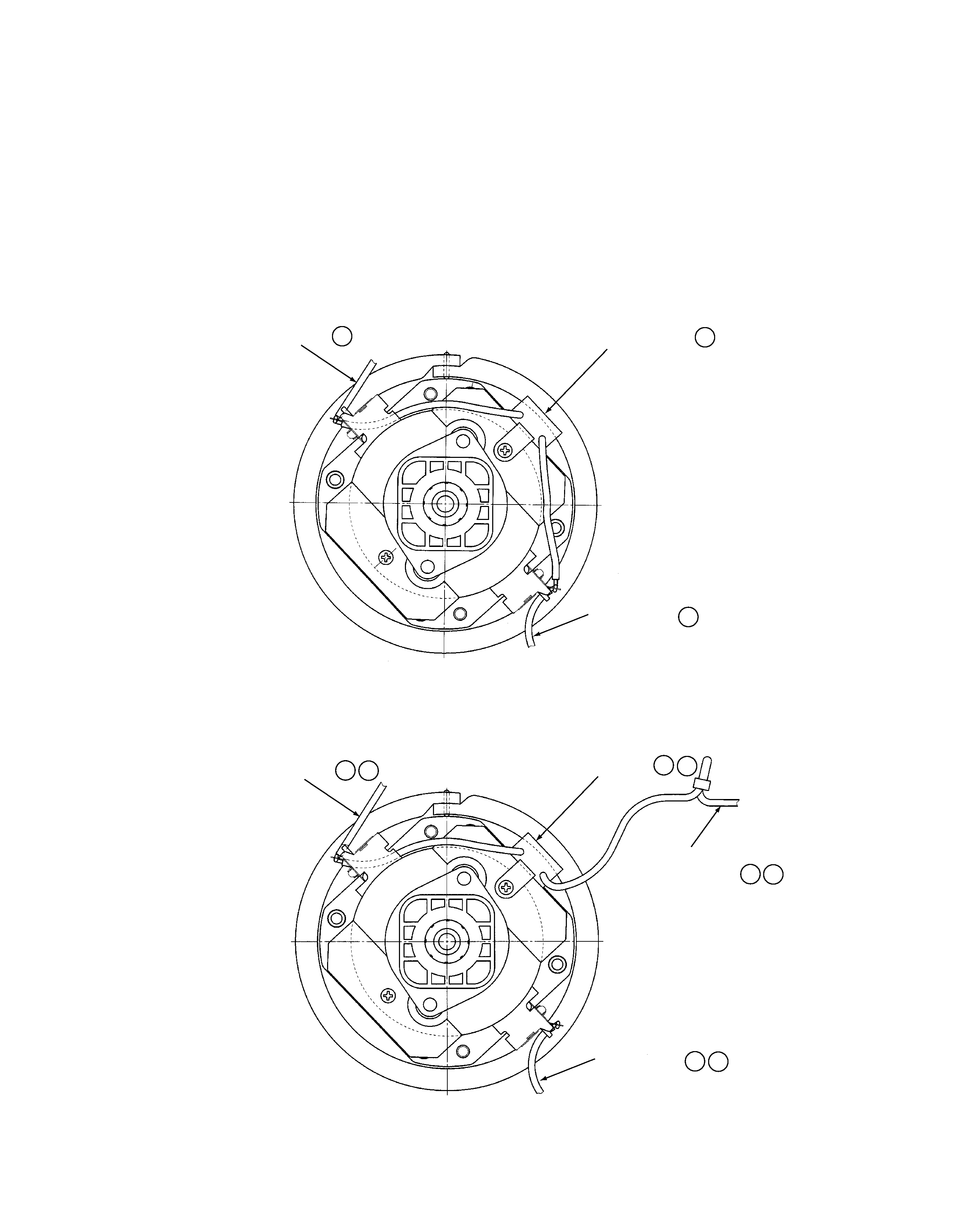
3.3 HOW TO REPLACE THE CARBON BRUSH ASSEMBLY
(1) Take off the two screws M4
10(35)(36)(36)from the carbon brush assemblies(34)(35)(35),then the carbon brush
assemblies can be removed.
(2) Put the new carbon brush assemblies(34)(35)(35) in place,and tighten the screws(35)(36)(36).
(3) Connect the lead wire with the terminal on the carbon brush assembly.
CAUTION!
(1) When replacing carbon brush assemblies,be sure to replace the worn-out carbon brush assembly with new one on
both sides.
(2) Be sure to connect the lead wire in the proper way as shown in Fig.3,4.
Wiring(brown) 74
Noise suppressor(VDE) 36
Wiring(blue) 74
Wiring(brown) 75
Noise suppressor(VDE) 37
Wiring(blue) 75
Double insulated
wire(Blue) 76
74
37
75
74
Fig.3 (CV-80D)
Fig.4 (CV-80DC/DP)
Belt
cover
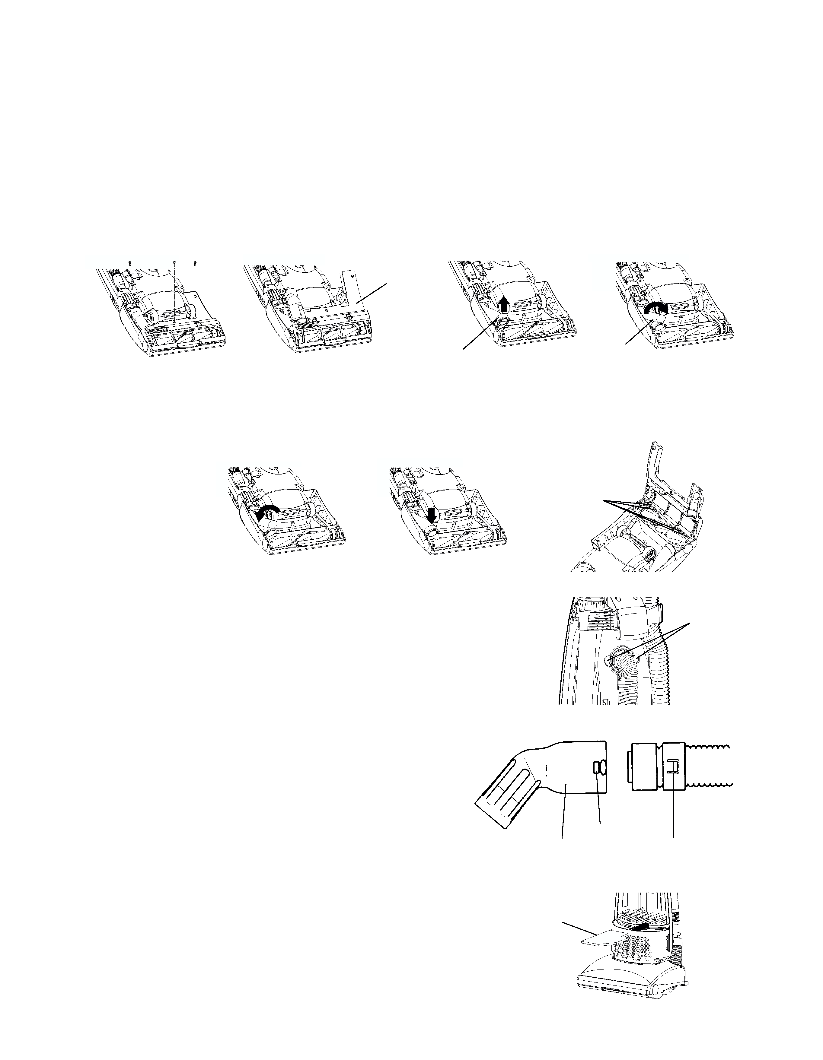
3.4 HOW TO CLEAR A BLOCKAGE
If the cleaner is used when the dust bag is full or any blockages are sucked in by accident,the air ducts may become
clogged. If this occurs,remove the blockages or obstructions from the air ducts as follows.
CAUTION: Be sure to disconnect the plug from the electrical outlet.
*DUCT HOSE
1. Change the dust bag.
2. Turn the cleaner over. Release the handle to the middle position. Remove the three screws(32)(33)(33) from the
belt cover(42)(43)(43).
3. Remove the belt cover,and take off the hose supporter(48)(49)(49) to check the duct hose(73)(74)(73).
4.To remove the duct hose,twist clockwise.
5. After removing blockage from the duct hose,reinstall the duct hose by twisting counterclockwise,and replace the
hose supporter on the case securely.
6. Place the four projections of the belt cover to the windows provided on the front end of the case and replace the
belt cover,and re-fasten the screws securely.
*FLEXIBLE HOSE(Fig.7)
1. To disconnect hose from the suction inlet,press two joints firmly.
2. After removing blockage from the hose and/or suction
inlet,replace the hose and connect securely.
*JOINT PIPE(Fig.8)
Blockages may be cleared by separating the curved joint pipe from
the hose. To separate the joint pipe,depress the two claws which
are located in the holes on both sides of the joint pipe and pull
apart. To re-connect push hose back into joint pipe and twist until
two claws locate with holes.
4. CARE OF AIR FILTERS
*MOTOR PROTECTION AIR FILTER(Fig.9)
Once or twice a year,or when it becomes visibly soiled,the motor
protection air filter(63)(64)(63) may need cleaning.
1. Remove the filter from the bottom of the bag compartment as
shown in Fig.9 and wash in warm water.
2. After washing the filter,dry thoroughly away from direct sunlight
and fit it back into the cleaner.
Hose supporter
Duct hose
Windows
Joints
Curved joint pipe
Holes
Claws
Motor protection
air filter
Fig.5
Fig.6
Fig.7
Fig.9
Fig.8