SM
0534
CPS318W(C3SM4)
CPX328W(C3XM4)
SPECIFICATIONS AND PARTS ARE SUBJECT TO CHANGE FOR IMPROVEMENT.
Multimedia LCD Projector
July 2003 Digital Media Division
SERVICE MANUAL
Be sure to read this manual before servicing. To assure safety from fire, electric shock, injury, harmful radi-
ation and materials, various measures are provided in this Hitachi Multimedia LCD Projector. Be sure to
read cautionary items described in the manual to maintain safety before servicing.
Caution
1. When replace the lamp, to avoid burns to your fingers. The lamp becomes too hot.
2. Never touch the lamp bulb with a finger or anything else. Never drop it or give it a shock. They may
cause bursting of the bulb.
3. This projector is provided with a high voltage circuit for the lamp. Do not touch the electric parts of
power unit (main), when turn on the projector.
4. Do not touch the exhaust fan, during operation.
5. The LCD module assembly is likely to be damaged. If replacing to the LCD LENS/PRISM assembly, do
not hold the FPC of the LCD module assembly.
6. Use the cables which are included with the projector or specified.
Service Warning
1. Features --------------------------------------------------- 2
2. Specifications--------------------------------------------- 2
3. Names of each part ------------------------------------- 3
4. Adjustment ------------------------------------------------ 5
5. Troubleshooting---------------------------------------- 12
6. Service points ------------------------------------------ 17
7. Wiring diagram ----------------------------------------- 30
8. Disassembly diagram--------------------------------- 36
9. Replacement parts list-------------------------------- 38
10.RS-232C communication ---------------------------- 39
11.Block diagram------------------------------------------- 45
12.Connector connection diagram -------------------- 46
13.Basic circuit diagram---------------------------------- 47
Contents
STA
NDB
Y/O
N
INPUT
KEY
STO
NE
RES
ET
LANP
TENP
POWER
Warning
The technical information and parts shown in this
manual are not to be used for: the development,
design, production, storage or use of nuclear, chemical,
biological or missile weapons or other weapons of
mass destruction; or military purposes; or purposes that
endanger global safety and peace. Moreover, do not
sell, give, or export these items, or grant permission for
use to parties with such objectives. Forward all inquiries
to Hitachi Ltd.
PJ650(C3XM4)
2
CP-S318(C3SM4) / CP-X328(C3XM4)
1. Features
High brightness high resolution
Full connectivity
Easy and flexible keystone adjustment
My screen
Wide angle lens
Low noise
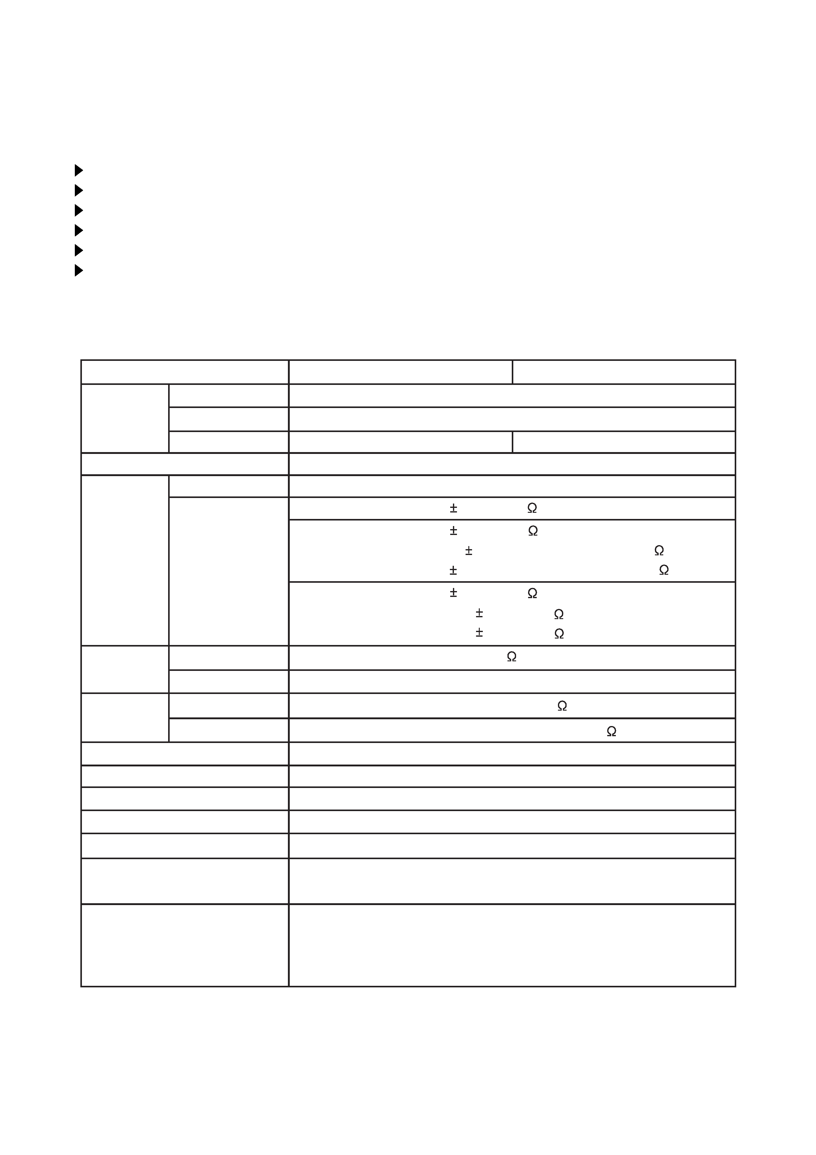
2. Specifications
Liquid crystal
panel
Lamp
Video input
RGB input /
output
Drive system
Panel size
Number of pixels
System
Level
Analog RGB
Sync.
Iuput
Output
Audio
Speaker output
Power supply
Power consumption
Dimensions
Weight
Temperature range
Accessories
TFT active matrix
CP-S318
CP-X328/PJ650
0.7 inches
800 (H) × 600 (V)
1024 (H) × 768 (V)
150W UHB
Composite
S-video
NTSC, PAL(BGDHI), SECAM, PAL-M, PAL-N, NTSC4.43, PAL60
Remote control transmitter × 1
RGB cable × 1
Video/Audio cable × 1
USB cable × 1
0.7Vp-p (75
termination)
TTL level
200mVrms, 47k
200mVrms, output impedance 1k
1.0W (mono)
AC100~120V/2.7A, AC220~240V/1.3A
240W
295 (W) × 87.5 (H) × 231 (D) mm
2.74kg (6.04lbs)
Operation : 0~35°C
Storage : -20~60°C
1.0 0.1Vp-p (75
termination)
0.3 0.1Vp-p (PAL/SECAM burst signal, 75
termination)
Y : 1.0 0.1Vp-p (75
termination)
C : 0.286 0.1Vp-p (NTSC burst signal, 75
termination)
POWER cord × 3
Battery × 2
Carrying bag × 1
User's manual (with Safety Instructions)× 1
Component
PB/PR : 0.7 0.1Vp-p (75
termination)
Y : 1.0 0.1Vp-p (75
termination)
CB/CR : 0.7 0.1Vp-p (75
termination)
3
CP-S318(C3SM4) / CP-X328(C3XM4)
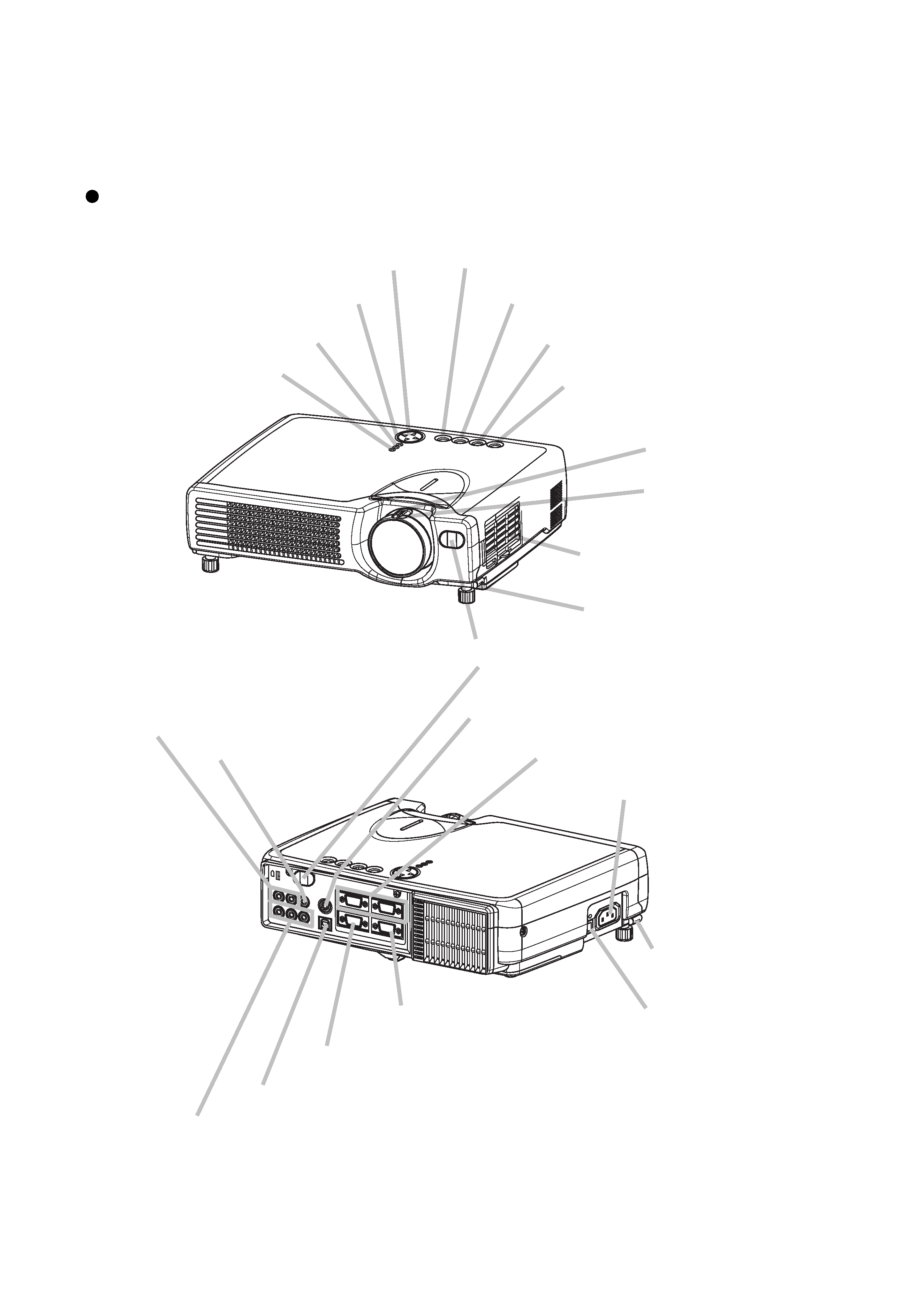
3. Names of each part
Parts names
STANDBY/ON
INPUT
KEYSTONE
RESET
LANP
TENP
POWER
Zoom ring
Focus ring
Air filter
Elevator button
Elevator button
KEYSTONE button
STANDBY/ON button
INPUT button
RESET button
STAN
DBY/O
N
INPU
T
KEY
STO
NE
RESE
T
LANP
TENP
POWER
MENU button
LAMP LED
TEMP LED
POWER LED
Remote sensor
AC power inlet
S-VIDEO IN port
RGB IN 1 and 2 ports
AUDIO IN R and L ports
VIDEO IN port
CONTROL port
RGB OUT port
USB port
COMPONENT VIDEO port
Power switch
4
CP-S318(C3SM4) / CP-X328(C3XM4)
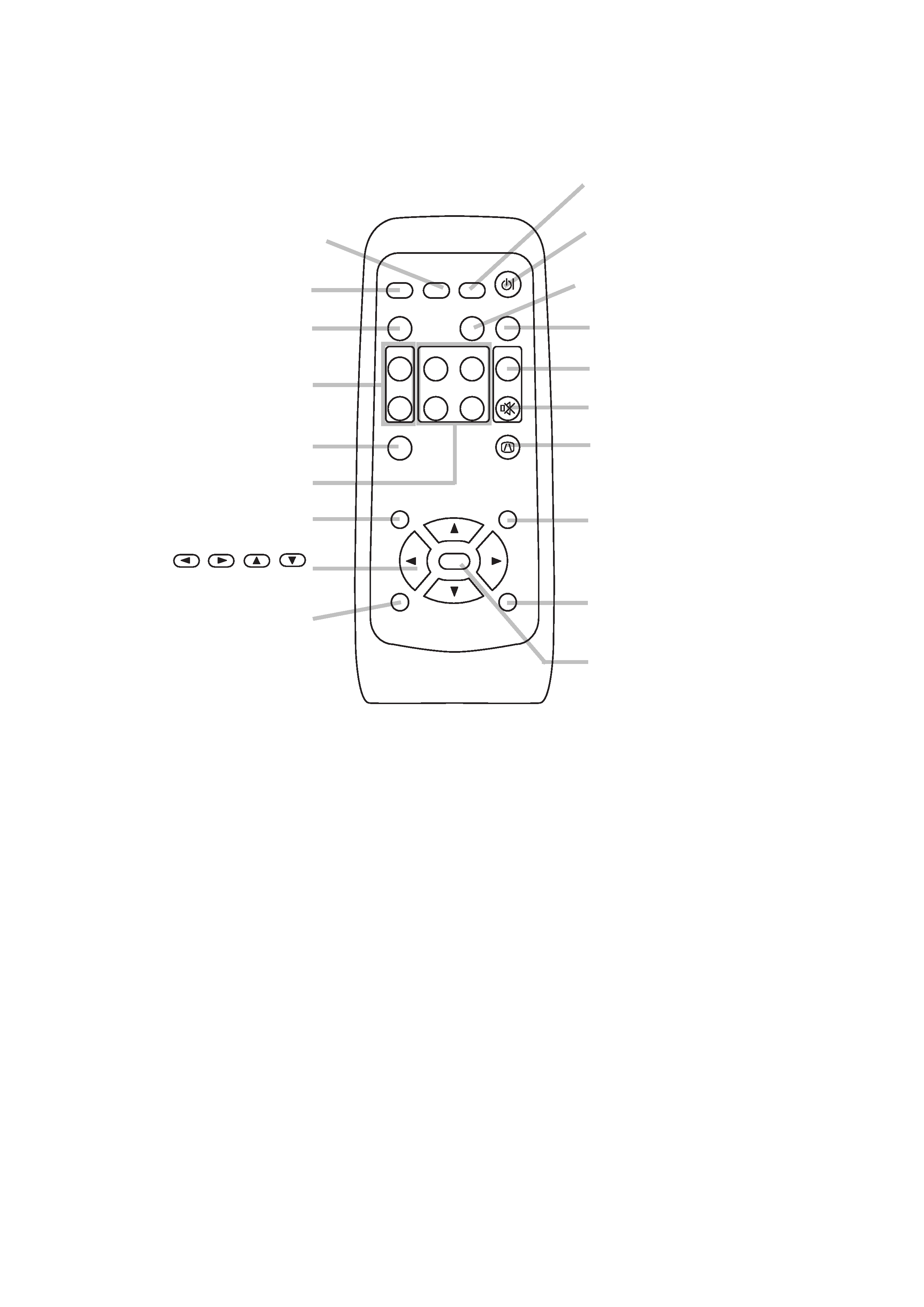
Remote control transmitter
STANDBY/ON button
VIDEO button
MENU button
RGB button
BLANK button
SEARCH button
VOLUME button
MUTE button
KEYSTONE button
ASPECT button
AUTO button
MAGNIFY button
KEYBOARD buttons
FREEZE button
POSITION button
ESC button
,,,
Cursor buttons
RESET button
ENTER button
VIDEO
ASPECT
HOME
END
MUTE
PAGE DOWN
KEYSTONE
FREEZE
OFF
ON
MENU
POSITION
ENTER
ESC
RESET
PAGE UP
VOLUME
MAGNIFY
AUTO
BLANK
RGB
SEARCH
STANDBY/ON
5
CP-S318(C3SM4) / CP-X328(C3XM4)
4-2 Ghost adjustment
Signals for internal adjustment
30%
30%
112/255
0/255
Adjustment procedure
1. Use DAC-P - GHOST - R: in the Adjustment
menu to adjust so that R color ghost is at a
minimum.
(Set the adjustment value to default, and then raise
the value. When a ghost appears to the left of a
vertical line, reduce the value by 2 steps.)
2. In the same way, use DAC-P - GHOST-G: in the
Adjustment menu to adjust so that G color ghost
is at a minimum.
3. In the same way, use DAC-P - GHOST-B: in the
Adjustment menu to adjust so that B color ghost
is at a minimum.
4. Adjustment
4-1 Before adjusting
4-1-1 Selection of adjustment
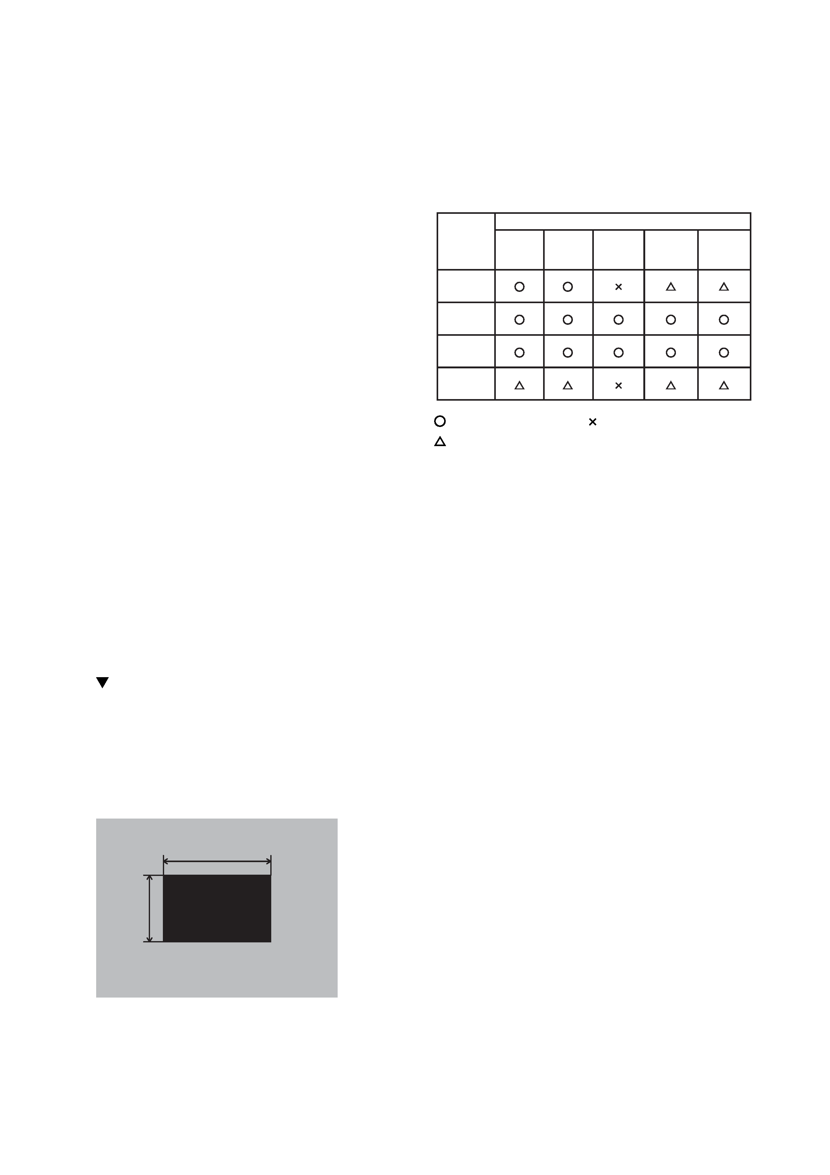
When any parts in the table 4-1 are changed, choose
the proper adjusting items with the chart.
Table 4-1: Relation between the replaced part and adjustment
Replaced
part
Ghost
(Chap.4-2)
Flicker
(Chap.4-3)
PSIG/NRSH
(Chap.4-4)
White
balance
(Chap.4-5)
Color
uniformity
(Chap.4-6)
Dichroic
optics unit
LCD/LENS
prism
assembly
PWB
assembly
drive
Lamp
unit
assembly
Adjustment
: means need for adjustment.
: means not need for adjustment.
: means recommended.
4-1-2 Setting of condition before adjustment
1. Before starting adjustment, warm up the projector
for about 10 minutes.(Blank white)
2. Set Zoom Wide to Max. And project an image
with more than 40 inches in diagonal size.
3. Normalizing the video adjustment.
(Press the [MENU] button of the Remote control
transmitter to display the MAIN menu, and then
press the [RESET] button. And select the
[DEFAULT]. Next, open MAIN menu and press the [
] key to display the PICTURE1 menu, then press
the [RESET] key to set to [DEFAULT].)
*note :The MAIN and PICTURE1 menu is not
reset with no signal.
4. Set the normal at OPT-WHISPER in the menu.
5. Reset KEYSTONE correction.
6. Perform all adjustments from the Adjustment
menu.
Perform the following operations to display the
Adjustment menu.
a. Press the [MENU] button of the Remote
control transmitter (the MAIN menu will
appear).
b. Next, press the [RESET] button one time. And
press the [RESET] button again for 5 seconds
or more (the Adjustment menu will appear).