CAUTION:
Before servicing this chassis, it is important that the service technician read the "Safety
Precautions" and "Product Safety Notices" in this service manual.
ATTENTION:
Avant d'effectuer l'entretien du châassis, le technicien doit lire les «Précautions de sécurité»
et les «Notices de sécurité du produit» présentés dans le présent manuel.
VORSICHT:
Vor Öffnen des Gehäuses hat der Service-Ingenieur die ,,Sicherheitshinweise" und ,,Hinweise
zur Produktsicherheit" in diesem Wartungshandbuch zu lesen.
SERV IC E M A N UA L
M A N UEL D 'E N TRETIE N
W A RTUN GSH A N D B UCH
Data contained within this Service
manual is subject to alteration for
improvement.
Les données fournies dans le présent
manuel d'entretien peuvent faire l'objet
de modifications en vue de perfectionner
le produit.
Die in diesem Wartungshandbuch
enthaltenen Spezifikationen können sich
zwecks Verbesserungen ändern.
NAMES»
SPECIFICATIONS AND PARTS ARE SUBJECT TO CHANGE FOR IMPROVEMENT
Monitor
December 1999
No. 0416
CPX1402MS

DESCRIPTION : 14 INCH CCTV WITH 1-CAMERA INPUT
HORIZONTAL RESOLUTION 450 LINES
1) SPECIFICATIONS
COLOR SYSTEM
: NTSC 3.58 / PAL-B
POWER INPUT
: AC 110-240V (50/60 Hz)
POWER CONSUMPTION
: 68W
VIDEO IMPEDANCE
: 75 Ohm BNC
SOUND OUTPUT
: 1.1
0.2W 8 Ohm
SPEAKER SIZE
: 77 mm
40 mm
VIDEO OUTPUT LEVEL
: 1.0 ~ 1.2Vp
p at 75 Ohm
VIDEO INPUT LEVEL
: 1.0 ~ 1.2Vp
p at 75 Ohm
AUDIO OUTPUT LEVEL
: RCA JACK TYPE
300
50mVrms
AUDIO INPUT LEVEL
: RCA JACK TYPE
300
50mVrms
SOUND DISTORTION
: Less Than 10%
HUM
: Less Than 10mVrms
BUZZ
: Less Than 200mVp
p
2) FEATURES
RASTER MUTING AT NO SIGNAL
PROTECTION CIRCUIT FOR X-RAY
S-VHS INPUT
VIDEO THROUGH-OUT
3) CONTROLS & SWITCHES
MAIN AC POWER S/W
: PUSH LOCK
FRONT
PICTURE CONTROL
: ROTARY
FRONT
(CONTRAST, BRIGHTNESS, TINT, COLOR, SHARPNESS)
VOLUME CONTROL
: ROTARY
FRONT
S-VHS/CAMERA SELECTION
: SLIDE SWITCH
BACK
VIDEO IMPEDANCE
: SLIDE SWITCH
BACK
4) LIGHTINGS
INDICATOR
: POWER ON (GREEN)
5) JACK & TERMINALS
2 BNC
: VIDEO INPUT/OUTPUT
2 AUDIO RCA
: AUDIO INPUT/OUTPUT
S-VHS MINI DIN
: S-VHS INPUT
AC INLET
: AC INPUT
1
SPECIFICATIONS OF CCTV COLOR MONITOR SET

6) ACCESSORIES
WARRANTY CARD
OWNER'S MANUAL
POWER CORD
7) CABINET SIZE
350(W) * 332(H) * 370(D)
8) PACKING
BOX OUT
: 437(W) * 427(H) * 450(D)
Q TY SET PER 40 FOOT FCL
: 675 SETS
Q TY SET PER 20 FOOT FCL
: 325 SETS
9) REMARKS
WEIGHT
: 14 Kg
2
Follow these safety, servicing and ESD Precautions to prevent damage and protect against
potential hazards, such as electrical shock and X-rays.
Safety Precautions
1. Be sure that all of the built-in protective devices are replaced.
Restore any missing protective shields.
2. When reinstalling the chassis and its assemblies,
be sure to restore all protective devices, including: nonmetallic control knobs
and compartment covers.
3. Make sure that there are no cabinet openings through which
people-particularly children-might insert fingers and contact dangerous
voltages. Such opening include the spacing between the picture tube and
the cabinet mask, excessively wide cabinet ventilation slots, and improperly
fitted back covers. If the measured resistance is less than 1.0 megohm or
greater than 5.2 megohms, an abnormality exists that must be corrected
before the unit is returned to the customer.
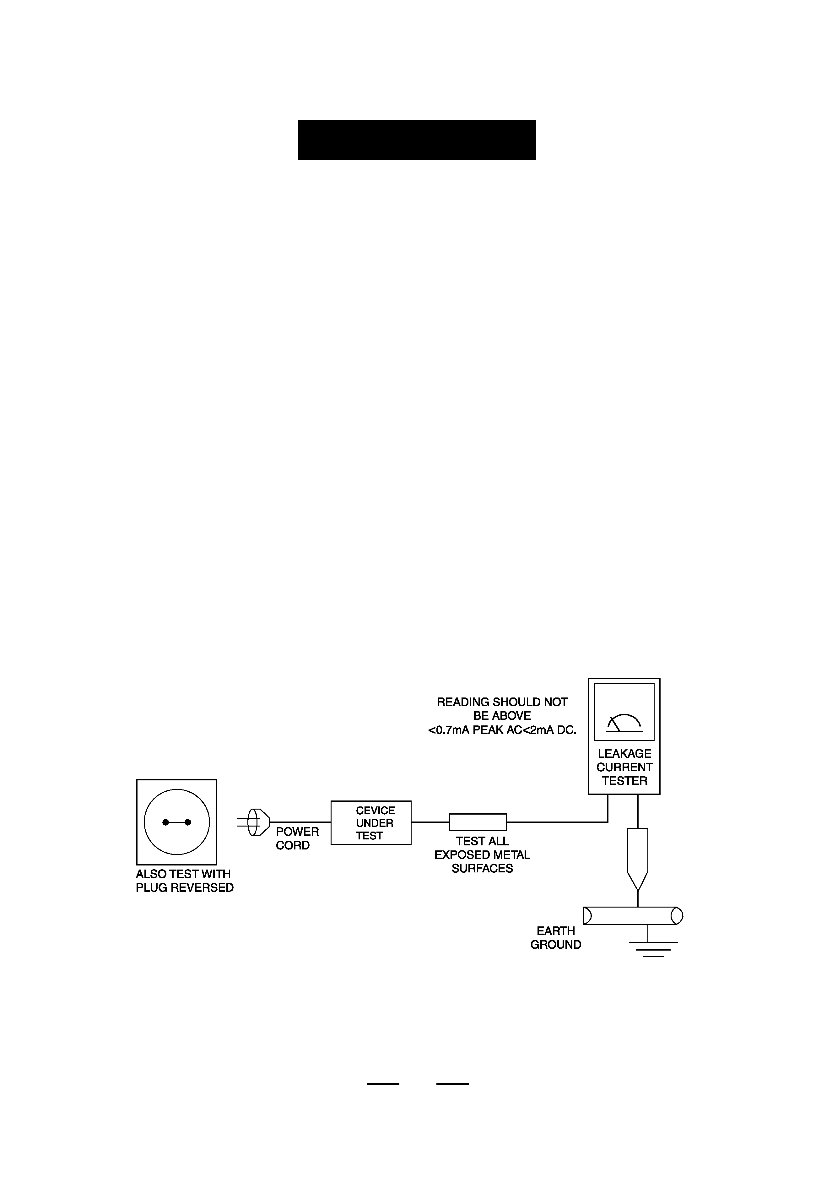
4. Leakage Current Hot Check (Figure 1-1):
Warning:Do not use an isolation transformer during this test.Use a
leakagecurrent tester or a metering system that complies with International
Electrotechnical Commission 65.(IEC 65)
3
FIGURE 1-1 AC LEAKAGE TEST
PRECAUTIONS

5. With the unit completely reassembled, plug the AC line cord directly into
the power outlet. @With the unit's AC switch first in the ON position and
then OFF, measure the current between a known earth ground (metal water
pipe,conduit, etc.) and all exposed metal parts, including: handle
brackets, metal cabinets, screwheads and control shafts. The current
measured should not exceed <0.7mA peak AC <2mA DC.
Reverse the power-plug in the AC outlet and repeat the test.
6.X-ray Limits:
The picture tube is especially designed to prohibit X-ray emissions.
To ensure continued X-ray protection, replace the picture tube only with one
that is the same type as the original. Carefully reinstall the picture tube
shields and mounting hardware; these also provide X-ray protection.
7. High Voltage Limits:
High voltage must be measured each time servicing is done on the B+,
horizontal deflection or high voltage circuits.
8. High voltage is maintained within specified limits by close-tolerance,
safety-related components and adjustments. If the high voltage exceeds the
specified limits, check each of the special components.
9. Design Alteration Warning:
Never alter or add to the mechanical or electrical design of this unit.
Example: Do not add auxiliary audio or video connectors. Such alterations
might create a safety hazard. Also, any design changes or additions will
void the manufacturer's warranty.
10. Components, parts and wiring that .appear to have overheated or that are
otherwise damaged should be replaced with parts that meet the original
specifications. Always determine the cause of damage or overheating, and correct any
potential hazards.
11. Observe the original lead dress, especially near the following areas:
Antenna wiring, sharp edges, and especially the AC and high voltage power
supplies. Always inspect for pinched,out-of-place, or frayed wiring.
Do not change the spacing between components and the printed circuit
board. Check the AC power cord for damage. Make sure that leads and
components do not touch thermally hot parts.
12. Picture Tube Implosion Warning:
The picture tube in this receiver employs "integral implosion" protection.
To ensure continued implosion protection, make sure that the replacement
picture tube is the same as the original.
13. Do not remove, install or handle the picture tube without first putting on
shatterproof goggles equipped with side shields.
Never handle the picture tube by its neck. Some "in-line" picture tubes are
equipped with i pernianentlv citticilell deflection yoke; do not try to remove
such "permanently attached" yokes from the picture tube.
4