Projector
CP
-X1200W/CP-X1250W
INT
ER
INPU
T
M1
-D
RGB
BNG
S-VIDEO
ST ANDBY
/ON
TE
MP
VIDEO
COMPONE
NT
LAMP
KEYST
ONE
SEA
RCH
RESE
T
MEN
U
FOCUS
LENS
SHIF
T
ZOOM
ENGLISH
FRANÇAIS
DEUTSCH
ESPAÑOL
ITALANO
NORSK
NEDERLANDS
PORTUGUÊS
b
m
a
n
1
Projector
CP
-X1200W/CP-X1250W
User
User ''s Manual Quick Guide
s Manual Quick Guide
Thank you for purchasing this projector.
· The information in this manual is subject to change without notice.
· The manufacturer assumes no responsibility for any errors that may appear in this manual.
· The reproduction, transmission or use of this document or contents is not permitted without express
written authority.
NOTE
WARNING
Before using, read the "User's Manual - Safety Guide" and
these manuals to ensure correct usage through understanding. After reading,
store them in a safe place for future reference.
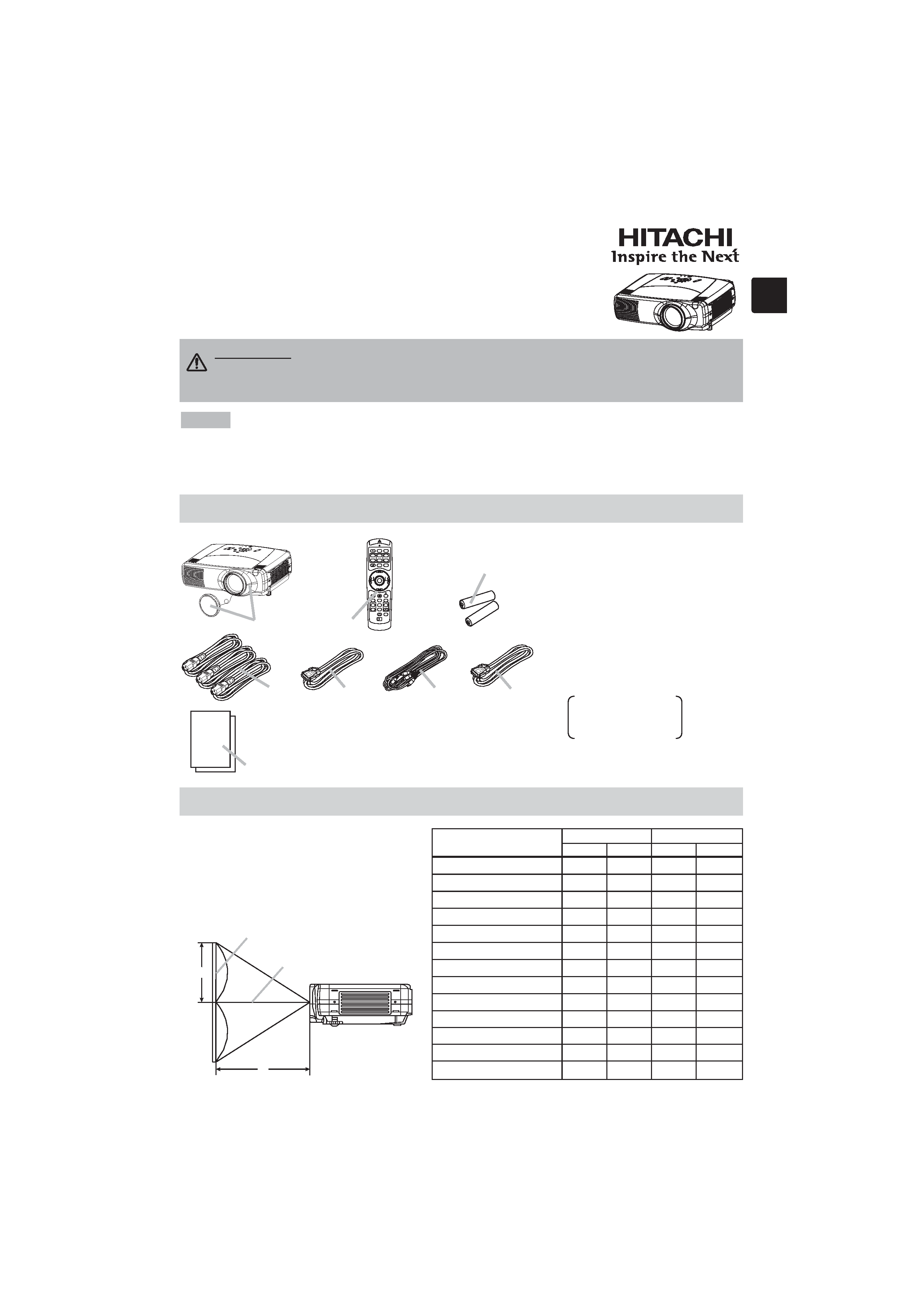
Contents Of Package
Contents Of Package
Refer to this table, in case of 4:3 aspect
ratios. The values a and b shown in the
table are calculated for a full size screen.
Arrangement
Arrangement
Lens center
Screen
1 Projector & Lens Cap
2 Power cords (UK, US, Europe)
3 RGB cable
4 Video/Audio cable
5 M1-D cable
6 Remote control
7 Batteries
(for the remote control)
8 User's Manuals
Safety Guide
Quick Guide
Operating Guide
INTE
R
INPUT
M1
-D
RG
B
BN
G
S-VIDEO
ST ANDBY
/ON
TE
MP
VIDEO
CO
MP
ONENT
LAMP
KEYST
ONE
SE
ARCH
RE
SET
MEN
U
FOCUS
LE
NS
SHIF
T
ZOO
M
STANDBY/ON
VIDEO
LASER INDICATOR
ESC
MENU
POSITION
RESET
AUTO
KEYSTONE
1 2 3
ID CHANGE
SEARCH
ON
OFF
FREEZE
MUTE
MAGNFY
PinP
VOLUME
RGB
BLANK
PREVIOUS
NEXT
ASPECT
ENTER
LASER
LENS SHIFT
+
++
FOCUS
ZOOM
IN
TE
R
IN
PU
T
M1-D
RGB
BNG
S-VIDE
O
ST
ANDBY
/O
N
TE
MP
VID
EO
COMPONE
NT
LAMP
KEY
ST
ON
E
SE
ARCH
RE
SET
ME
NU
FOCUS
LEN
SSHI
FT
ZO
OM
Side view
7
6
1
23
4
5
8
Screen Size
[inch (m)]
a [inch (m)]
b [inch (cm)]
Min.
Max.
m:n=1:1 m:n=10:0
40 (1.0)
46(1.2)
71(1.8)
12(30)
24(61)
60 (1.5)
71(1.8) 107(2.7) 18(46)
36(91)
70 (1.8)
83(2.1) 126(3.2) 21(53)
42(107)
80 (2.0)
95(2.4) 144(3.7) 24(61)
48(122)
100 (2.5)
120(3.0) 181(4.6) 30(76)
60(152)
120 (3.0)
144(3.7) 217(5.5) 36(91)
72(183)
150 (3.8)
181(4.6) 272(6.9) 45(114) 90(229)
200 (5.1)
243(6.2) 364(9.2) 60(152) 120(305)
250 (6.4)
304(7.7) 455(11.6) 75(191) 150(381)
300 (7.6)
366(9.3) 547(13.9) 90(229) 180(457)
350 (8.9)
427(10.9) 638(16.2) 105(267) 210(533)
400 (10.2)
489(12.4) 730(18.5) 120(305) 240(610)
500 (12.7)
612(15.5) 913(23.2) 150(381) 300(762)
2
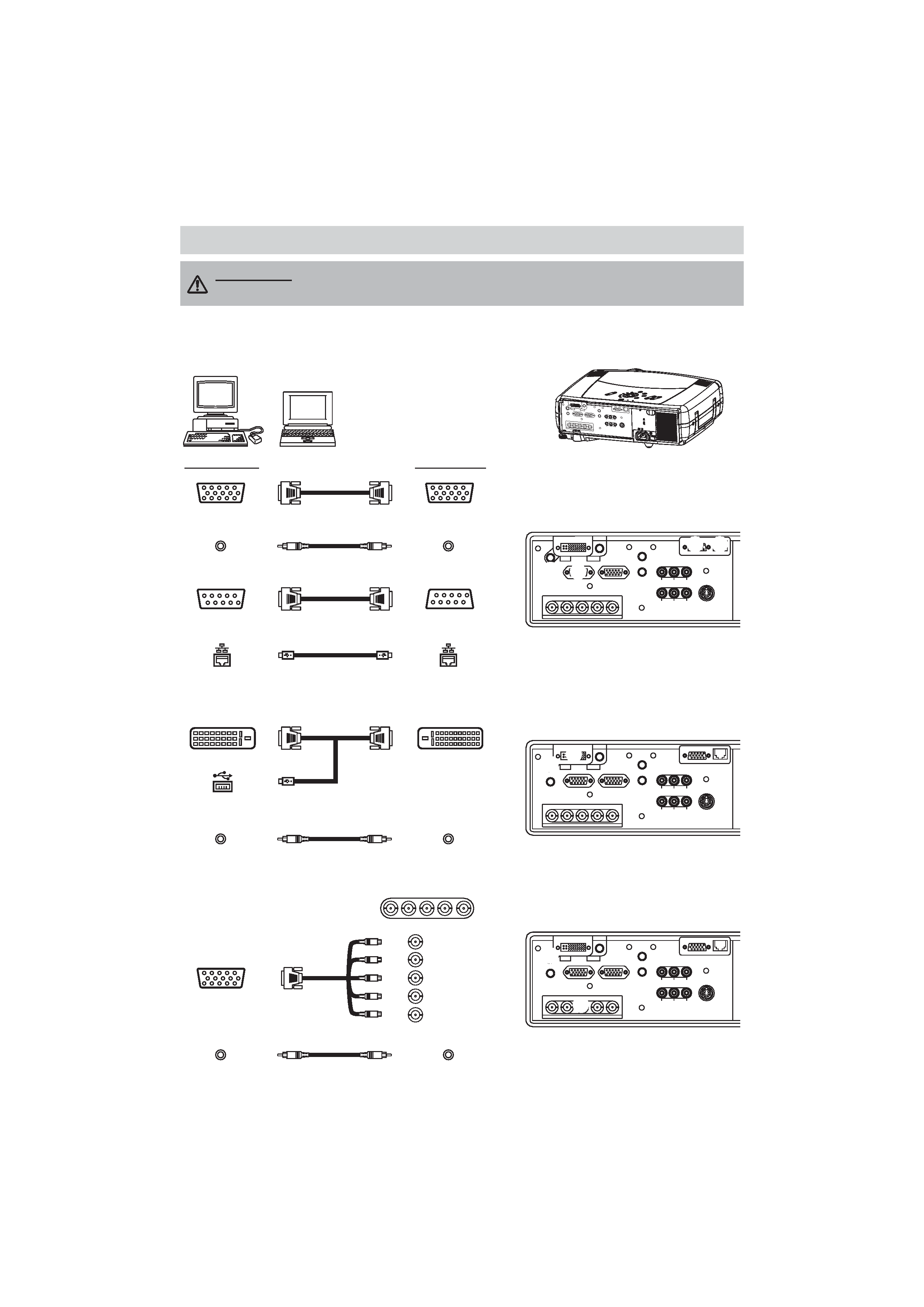
Please refer to the following for connecting your devices. See the rear of the projector. You can see
the ports.
Connecting Y
Connecting Your Devices
our Devices
INTER
INPUT
M1-D
RGB
BNG
S-VIDEO
STANDBY/ON
TEMP
VIDEO
COMPONENT
LAMP
KEYSTONE
SEARCH
RESET
MENU
FOCUS
LENS SHIFT
ZOOM
VIDEO
R-AUDIO IN-L
S-VIDEO
BNC
RGB
AUDIO IN1
AUDIO IN2
RGB OUT
AUDIO OUT
REMOTE CONTR
OL
R/CR/PR
G/Y
B/CB/PB
H
V
Y
CONTROL
NETWORK
CR/PR Ca/Pa
R/CR/PR G/Y B/CB/PB H
V
Connecting to a computer
WARNING · Install the projector in a suitable environment according to
instructions of the "User's Manual Safety Guide".
VIDEO
R-AUDIO IN-L
S-VIDEO
BNC
RGB
AUDIO IN1
AUDIO IN2
RGB OUT
AUDIO OUT
REMOTE CONTROL
R/CR/PR
G/Y
B/CB/PB
HV
Y
CONTROL
NETWORK
CR/PR Ca/Pa
A
E
F G
REMOTE CONTROL
VIDEO
R-AUDIO IN-L
S-VIDEO
BNC
RGB
AUDIO IN1
AUDIO IN2
RGB OUT
AUDIO OUT
G/Y
H
V
Y
CONTROL
NETWORK
CR/PR Ca/Pa
R/CR/PR
B/CB/PB
B
D
REMOTE CONTROL
VIDEO
R-AUDIO IN-L
S-VIDEO
BNC
RGB
AUDIO IN1
AUDIO IN2
RGB OUT
AUDIO OUT
R/CR/PR
G/Y
B/CB/PB
HV
Y
CONTROL
NETWORK
CR/PR Ca/Pa
C
D
Computer
Projector
RGB out
RGB cable
RGB
Audio out
Stereo Mini cable
AUDIO IN 2
RS-232C port
RS-232C cable
CONTROL
Network port
CAT-5 cable
NETWORK
If using a M1-D input (to mouse control)
If using a BNC input
DVI port
M1-D
USB port
M1-D cable
Audio out
Stereo Mini cable
AUDIO IN 1
BNC cable
RGB out
R/CR/PR
G/Y
B/CB/PB
H
V
C
D
B
G
F
E
A
D
Audio out
Stereo Mini cable
AUDIO IN 1
3
REMOTE CONTROL
VIDEO
R-AUDIO IN-L
S-VIDEO
BNC
RGB
AUDIO IN1
AUDIO IN2
RGB OUT
AUDIO OUT
R/CR/PR
G/Y
B/CB/PB
HV
Y
CONTROL
NETWORK
CR/PR Ca/Pa
L
REMOTE CONTROL
VIDEO
R-AUDIO IN-L
S-VIDEO
BNC
RGB
AUDIO IN1
AUDIO IN2
RGB OUT
AUDIO OUT
R/CR/PR
G/Y
B/CB/PB
HV
Y
CONTROL
NETWORK
CR/PR Ca/Pa
M
VIDEO
R-AUDIO IN-L
S-VIDEO
BNC
RGB
AUDIO IN1
AUDIO IN2
RGB OUT
AUDIO OUT
R/CR/PR
G/Y
B/CB/PB
HV
Y
CONTROL
NETWORK
CR/PR Ca/Pa
REMOTE CONTROL
H I
REMOTE CONTROL
VIDEO
R-AUDIO IN-L
S-VIDEO
BNC
RGB
AUDIO IN1
AUDIO IN2
RGB OUT
AUDIO OUT
R/CR/PR
G/Y
B/CB/PB
HV
Y
CONTROL
NETWORK
CR/PR Ca/Pa
H
J
REMOTE CONTROL
VIDEO
R-AUDIO IN-L
S-VIDEO
BNC
RGB
AUDIO IN1
AUDIO IN2
RGB OUT
AUDIO OUT
R/CR/PR
G/Y
B/CB/PB
HV
Y
CONTROL
NETWORK
CR/PR Ca/Pa
H
K
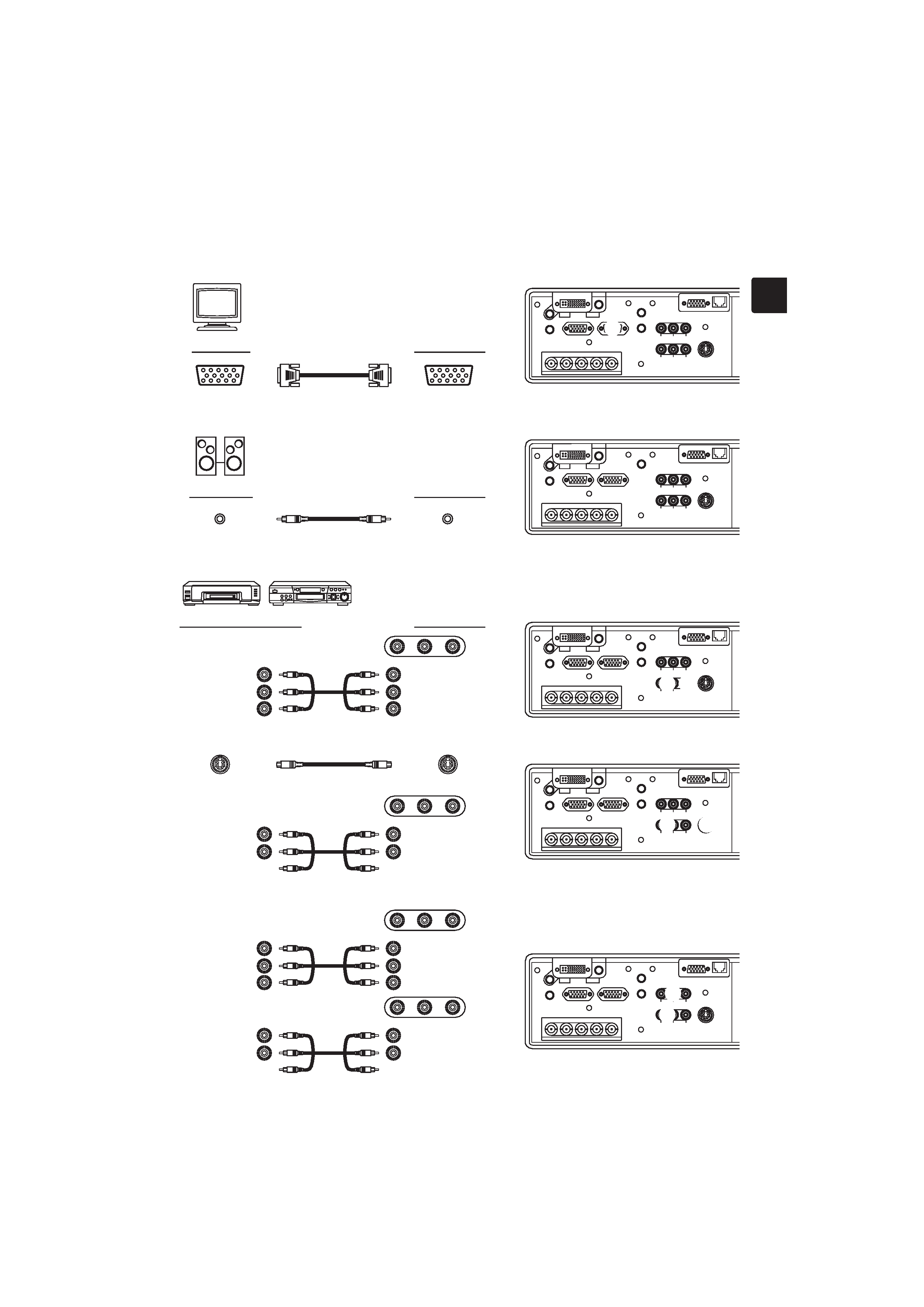
Monitor
Projector
RGB in
RGB cable
RGB OUT
Connecting to a monitor
Speaker
Projector
Connecting to a speaker (with amplifier)
Audio in
Stereo Mini cable
AUDIO OUT
M
VCR/DVD Player
Projector
Connecting to a VCR/DVD Player
If using a s-video signal
If using a component signal
R-AUDIO IN-L VIDEO
R-AUDIO IN-L VIDEO
COMPONENT
S-video out
S-video cable
S -VIDEO
J
L
CR/PR
CB/PB
Y
CR/PR out
CB/PB out
Y out
R-AUDIO IN-L VIDEO
R-AUDIO IN
AUDIO IN-L
Audio out (R)
Audio out (L)
Audio out (R)
Audio out (L)
R-AUDIO IN
AUDIO IN-L
R-AUDIO IN
AUDIO IN-L
VIDEO IN
Audio out (R)
Audio out (L)
Video out
H
H
K
H
I
4
INTER
INPUT
M1-D
RGB
BNG
S-VIDEO
STANDBY/ON
TEMP
VIDEO
COMPONENT
LAMP
KEYSTONE
SEARCH
RESET
MENU
FOCUS
LENS SHIFT
ZOOM
VIDEO
R-AUDIO IN-L
S-VIDEO
BNC
RGB
AUDIO IN1
AUDIO IN2
RGB OUT
AUDIO OUT
REMOTE CONTR
OL
R/CR/PR
G/Y
B/CB/PB
H
V
Y
CONTROL
NETWORK
CR/PR Ca/Pa
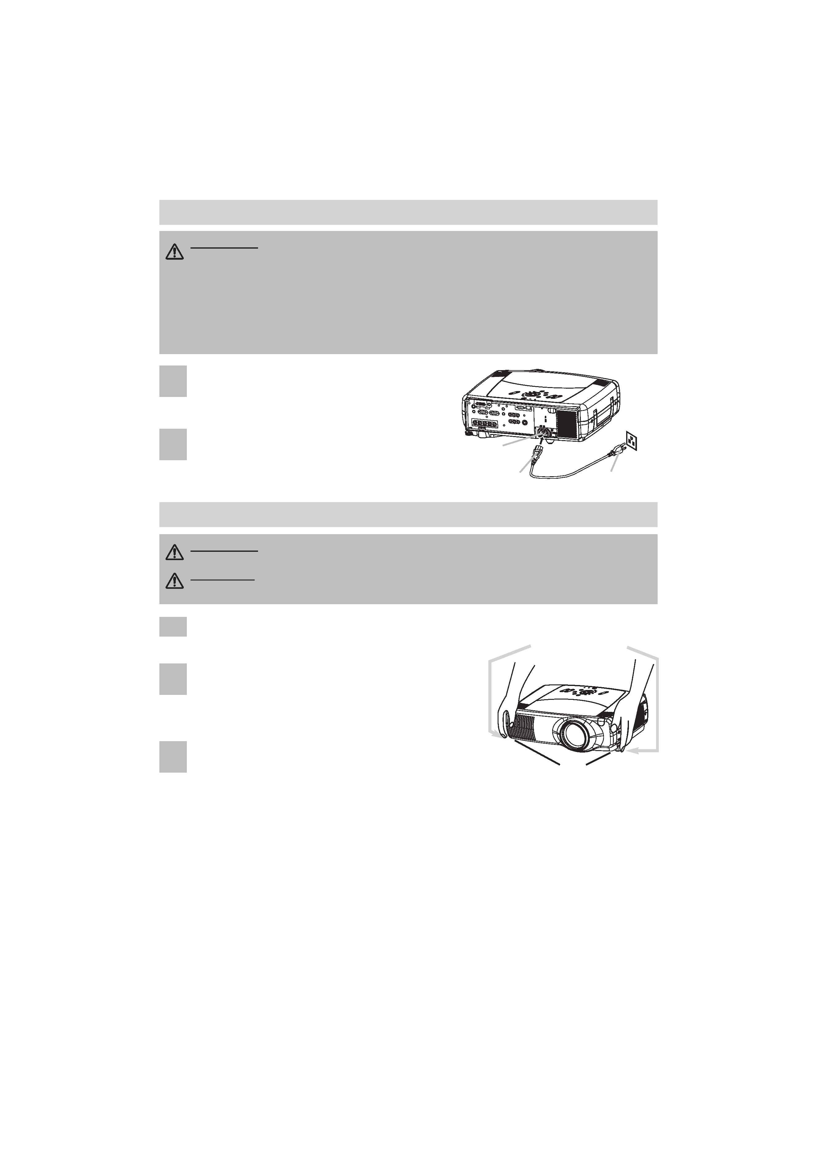
Connecting The Power Supply
Connecting The Power Supply
Adjusting The Projector's Elevator
Adjusting The Projector's Elevator
WARNING · Use extra caution when connecting the power cord as incorrect or faulty
connections may result in fire and/or electrical shock. Please adhere to the "User's manual
Safety Guide" and the following.
· Only plug the power cord into outlets rated for use with the power cord's specified voltage range.
· Only use the power cord that came with the projector. If it is damaged, contact your dealer to
newly get correct one.
· Never modify the power cord. Never attempt to defeat the ground connection of the three-pronged plug.
· Make sure that you firmly connect the power cord to the projector and wall outlet.
1
Connect the connector of the power cord to
the AC inlet of the projector.
2
Firmly plug the power cord's plug into the
outlet.
AC Inlet
Connector
Plug
Outlet
WARNING · Do not touch about the lens and ventilation openings during use or
immediately after use to prevent a burn.
CAUTION · To prevent damaging the projector and injuring yourself, always
hold the projector whenever using the elevator buttons to adjust the elevator feet.
Press and hold in the elevator buttons.
2
Raise or lower the projector to the desired height and
then release the elevator buttons.
When you release the elevator buttons, the elevator
feet will lock into position.
3
As necessary, you can also finely adjust the height of
the projector by twisting the elevator feet by hand.
Elevator buttons
Elevator feet
IN
TE
R
IN
PU
T
M1-
D
RGB
BNG
S-V
ID
EO
ST
AND
BY
/ON
TE
MP
VIDE
O
CO
MPO
NE
NT
LAMP
KE
YS
TO
NE
SEA
RCH
RE
SE
T
MEN
U
FO
CUS
LEN
SS
HIF
T
ZOO
M
1