SM0525
SPECIFICATIONS AND PARTS ARE SUBJECT TO CHANGE FOR IMPROVEMENT.
Multimedia LCD Projector
October 2002 Digital Media Division
SERVICE MANUAL
Be sure to read this manual before servicing. To assure safety from fire, electric shock, injury, harmful radia-
tion and materials, various measures are provided in this Hitachi Multimedia LCD Projector. Be sure to read
cautionary items described in the manual to maintain safety before servicing.
Caution
1. When replacing the lamp, avoid burns to your fingers. The lamp becomes very hot.
2. Never touch the lamp bulb with a finger or anything else. Never drop it or give it a shock. They may cause
bursting of the bulb.
3. This projector is provided with a high voltage circuit for the lamp. Do not touch the electric parts of power
unit (main), when turn on the projector.
4. Do not touch the exhaust fan, during operation.
5. The LCD module assembly is likely to be damaged. If replacing to the LCD module assembly, do not hold
the FPC of the LCD module assembly.
6. Use the cables which are included with the projector or specified.
Service Warning
1. Features --------------------------------------------------- 2
2. Specifications--------------------------------------------- 2
3. Names of each part ------------------------------------- 3
4. Adjustment ------------------------------------------------ 5
5. Troubleshooting---------------------------------------- 12
6. Service points ------------------------------------------ 17
7. Block diagram ------------------------------------------ 30
8. Connector connection diagram -------------------- 31
9. Wiring diagram ----------------------------------------- 32
10.Basic circuit diagram---------------------------------- 39
11.Disassembly diagram--------------------------------- 55
12.Replacement parts list-------------------------------- 57
13.RS-232C communication ---------------------------- 58
Contents
CPS225WA (C3S2A)
CPX275WA (C3X2A)
PJ501 (C3S3VS)
PJ551 (C3XM3VS)
PJ500-2 (C3S2A)
PJ550-2 (C3X2A)
2
3
CP-S225WA
CP-X275WA
1. Features
1,200lm, 2.49kg (5.49lbs) (CPS225WA, CPX275WA, PJ500-2, PJ550-2)
Easy and flexible keystone adjustment
Wide angle lens
Low noise
2. Specifications
CPS225WA / PJ500-2 / PJ501
CPX275WA / PJ550-2 / PJ551
My Screen (PJ501, PJ551 only)
1,500 ANSI lumens, 2.7kg (6lbs) (PJ501, PJ551)
2
CP-S225WA
CP-X275WA
3
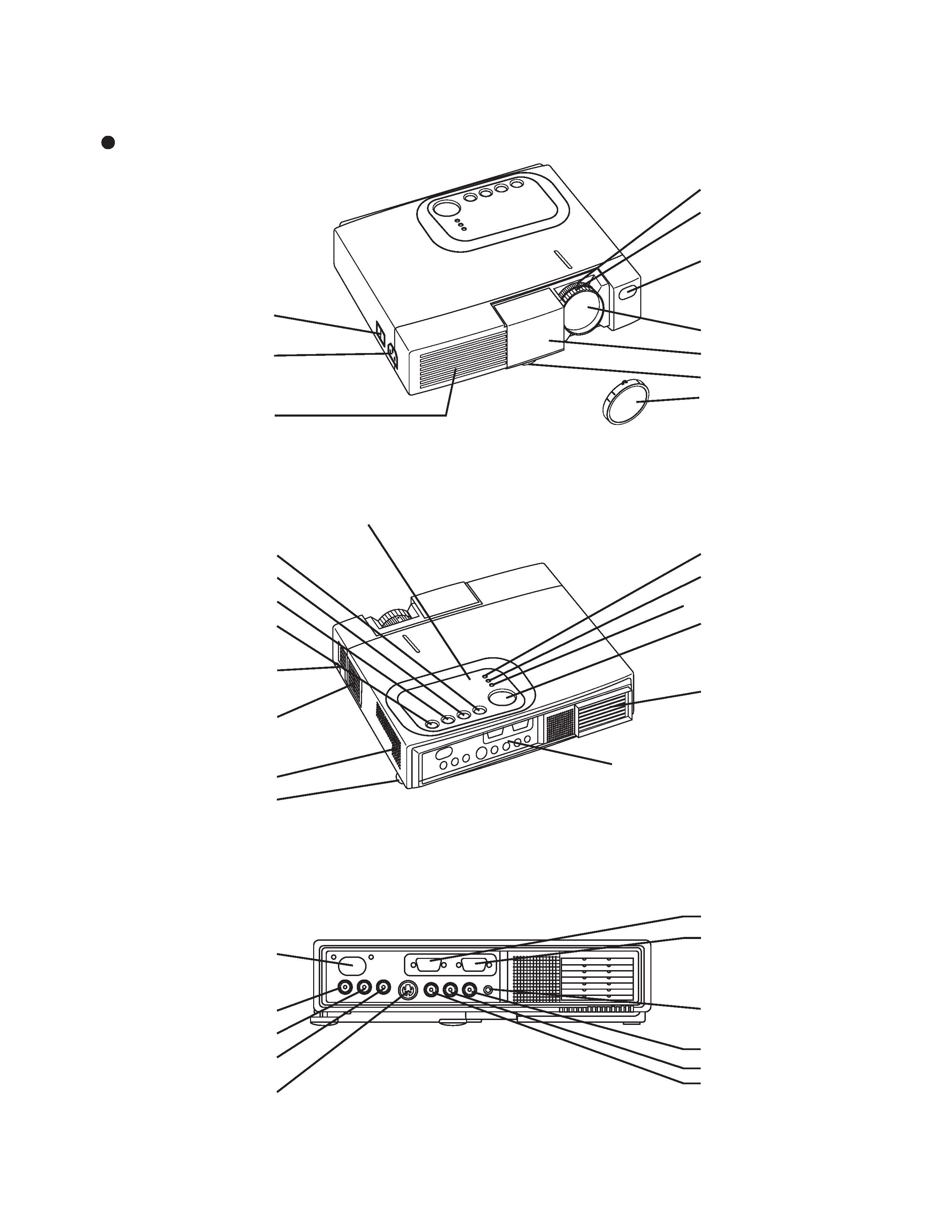
Remote Control Sensor
COMPONENT
Y Terminal
CB/PB Terminal
CR/PR Terminal
S-VIDEO Terminal
RGB Terminal
CONTROL Terminal
AUDIO Terminal
AUDIO
R Terminal
L Terminal
VIDEO Terminal
TERMINAL PANEL
3. Names of each part
Parts names
RESET Button
KEYSTONE Button
INPUT Button
STANDBY/ON Button
Foot Adjuster Button
Air Filter and Intake
(for the Cooling Fan)
Speaker
Rear Foot Adjuster
LAMP Indicator
TEMP Indicator
POWER Indicator
MENU Button
Ventilation Openings
(Exhaust)
Terminal Panel (Refer below)
Power Switch
AC Inlet
(to the Power Cord)
Ventilation Openings
(Intake)
Zoom Knob
Focus Ring
Remote Control Sensor
Lens
Slide Lens door
Foot Adjuster
Control Panel
FRONT / LEFT / VIEW
REAR / RIGHT / VIEW
Lens Cap (not CPS225WA
or CPX275WA)
4
5
CP-S225WA
CP-X275WA
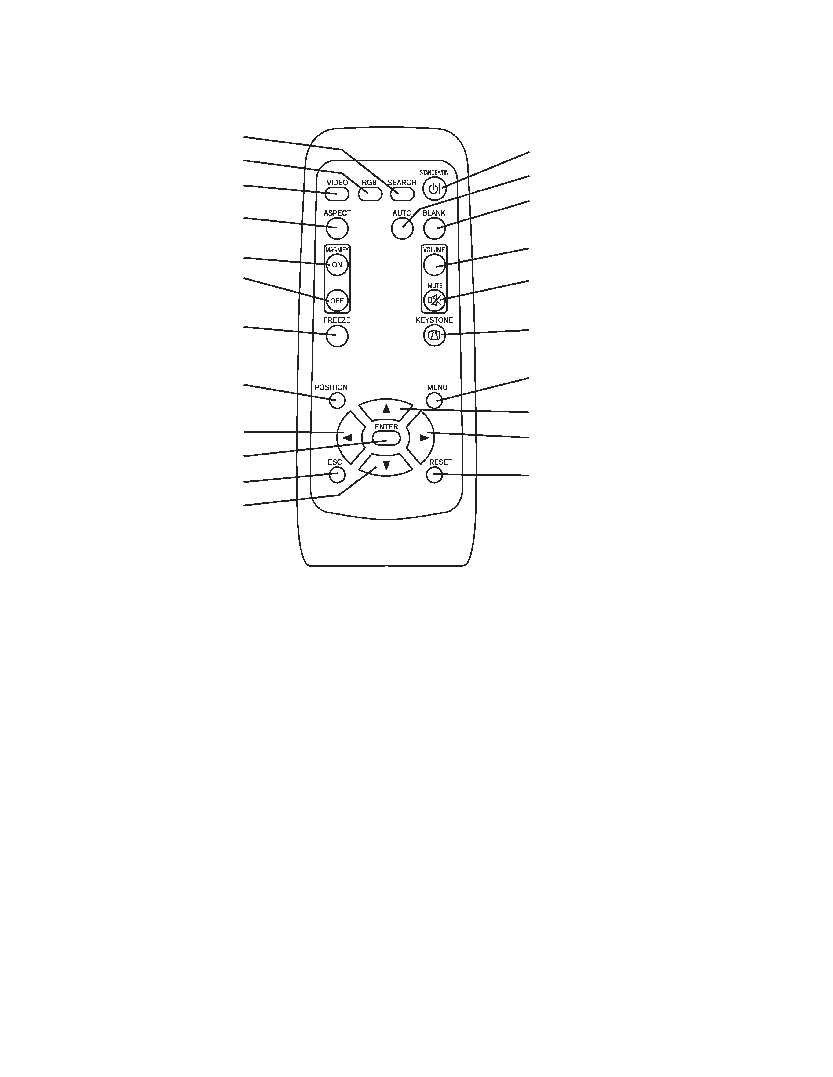
Remote control transmitter
SEARCH Button
RGB Button
VIDEO Button
ASPECT Button
MAGNIFY
ON Button
OFF Button
FREEZE Button
POSITION Button
[Left] Arrow Button
ENTER Button
ESC (Escape) Button
[Down] Arrow Button
STANDBY/ON Button
AUTO Button
BLANK Button
VOLUME Button
MUTE Button
KEYSTONE Button
MENU Button
[Up] Arrow Button
[Right] Arrow Button
RESET Button
4
CP-S225WA
CP-X275WA
5
4-2 Ghost adjustment
Signals for internal adjustment
Adjustment procedure
1. Use DAC-P - GHOST - R: in the Adjustment menu
to adjust so that R color ghost is at a minimum.
(Set the adjustment value to default, and then raise the
value. When a ghost appears to the left of a vertical
line, reduce the value by 2 steps.)
2. In the same way, use DAC-P - GHOST-G: in the
Adjustment menu to adjust so that G color ghost is
at a minimum.
3. In the same way, use DAC-P - GHOST-B: in the
Adjustment menu to adjust so that B color ghost is
at a minimum.
4. Adjustment
4-1 Before adjusting
4-1-1 Selection of adjustment
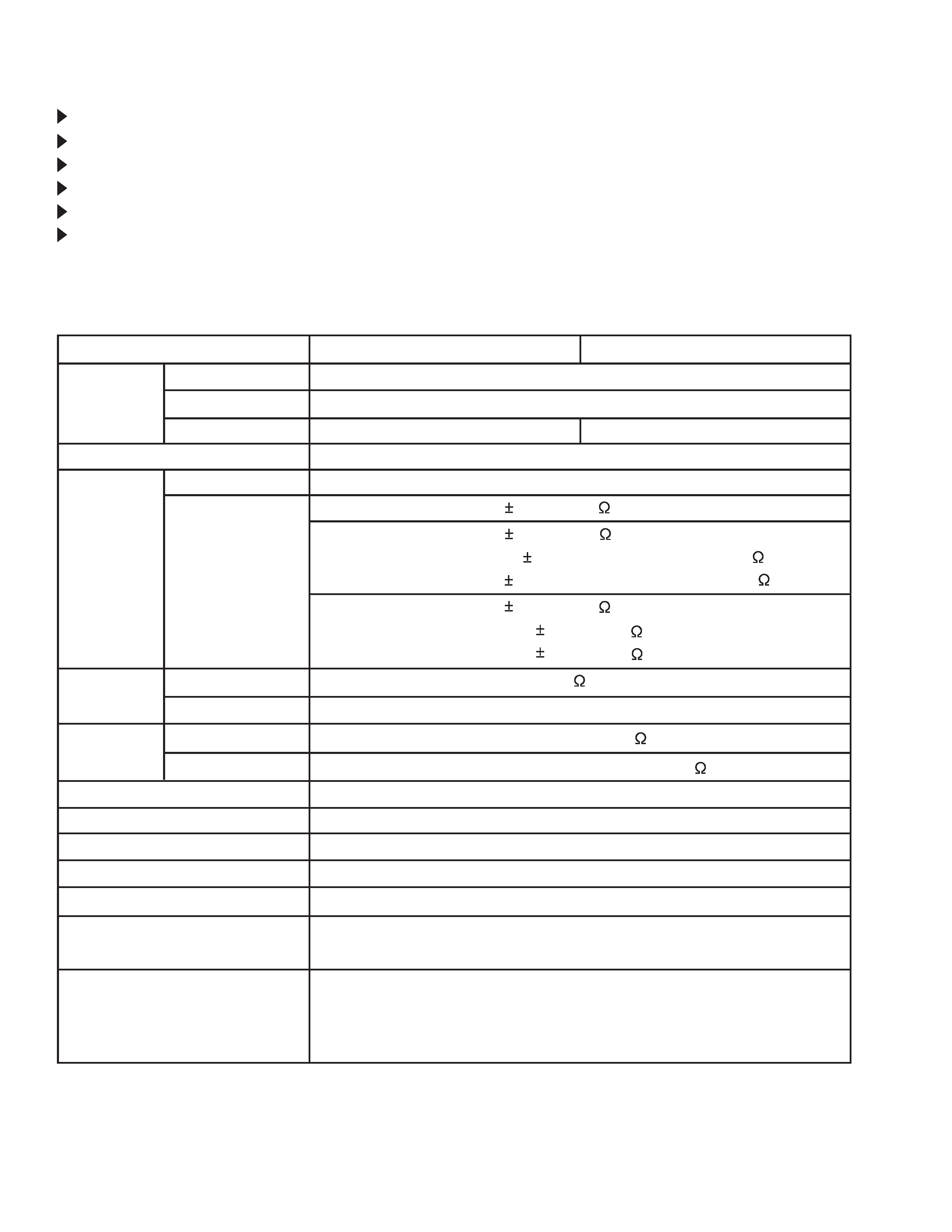
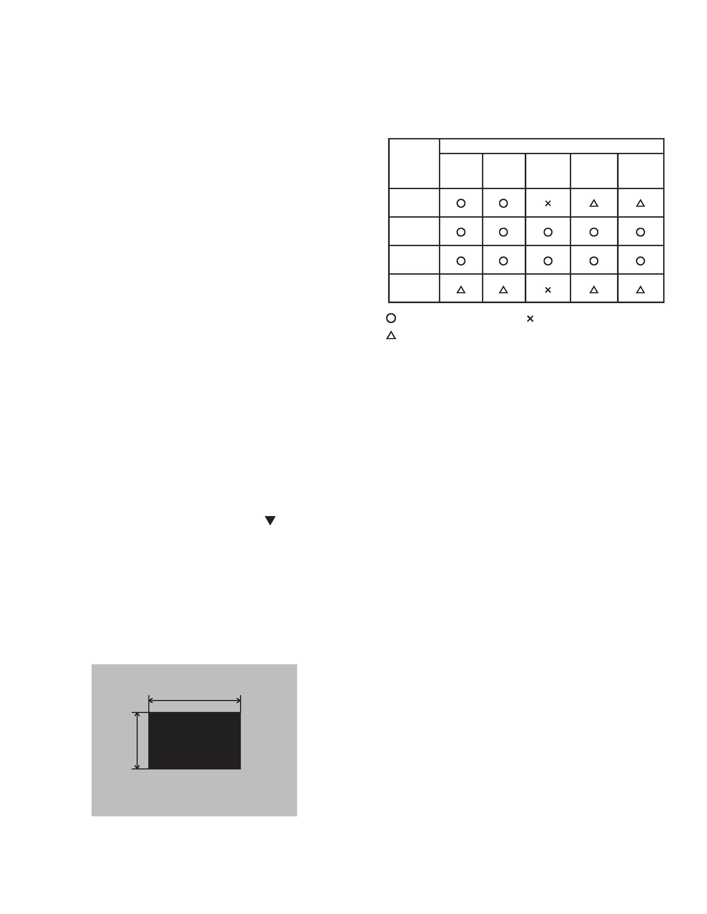
When any parts in the table 4-1 are changed, choose
the proffer adjusting items with the chart.
Table 4-1: Relation between the replaced part and adjustment
: means need for adjustment. : means not need for adjustment.
: means recommended.
4-1-2 Setting of condition before adjustment
1. Before starting adjustment, warm up the projector
for about 10 minutes.(Blank white)
2. Set Zoom Wide to Max. And project an image with
more than 40 inches in diagonal size.
3. Normalizing the video adjustment.
(Press the [MENU] button of the Remote control
transmitter to display the MAIN menu, and then press
the [RESET] button. And select the [DEFAULT]. Next,
open MAIN menu and press the [ ] key to display
the PICTURE1 menu, then press the [RESET] key to
set to [DEFAULT].)
*note :The MAIN and PICTURE1 menu is not reset
with no signal.
4. Set the normal at OPT-WHISPER in the menu.
5. Reset KEYSTONE correction.
6. Perform all adjustments from the Adjustment menu.
Perform the following operations to display the
Adjustment menu.
a. Press the [MENU] button of the Remote control
transmitter (the Setup menu will appear).
b. Next, press the [RESET] button one time. And
press the [RESET] button again for 5 seconds
or more (the Adjustment menu will appear).