CAUTION:
Before servicing this chassis, it is important that the service technician read the "Safety
Precautions" and "Product Safety Notices" in this service manual.
ATTENTION:
Avant d'effectuer l'entretien du châassis, le technicien doit lire les «Précautions de sécurité»
et les «Notices de sécurité du produit» présentés dans le présent manuel.
VORSICHT:
Vor Öffnen des Gehäuses hat der Service-Ingenieur die ,,Sicherheitshinweise" und ,,Hinweise
zur Produktsicherheit" in diesem Wartungshandbuch zu lesen.
SERVICE MANUAL
MANUEL D'ENTRETIEN
WARTUNGSHANDBUCH
Data
contained
within
this
Service
manual
is
subject
to
alteration
for
improvement.
Les données fournies dans le présent
manuel d'entretien peuvent faire l'objet
de modifications en vue de perfectionner
le produit.
Die
in
diesem
Wartungshandbuch
enthaltenen Spezifikationen können sich
zwecks Verbesserungen ändern.
December 1998
Colour Television
Model
C1422R/RS
C1422T/TS
C2122T
CP1422R
CP2122R
CP1422T/TS
CP2022T
CP2122T
CP1422T-481
CP2122T-481
CP1422T-491
CP2022T-491
CP2122T-491
CS1422R
CS2022R
CS2122R
CL1422R/RS
CL2122R
C1432TB/TY
CP1432RB
CP1432RY
No. 0102
SPECIFICATIONS AND PARTS ARE SUBJECT TO CHANGE FOR IMPROVEMENT
Chassis
F1R
F1Y
F4Y
F1GR
F4GR
F1GY
F2GY
F4GY
F1HY
F4HY
F1HY
F2HY
F4HY
F1KR
F2KR
F4KR
F1FR
F4FR
F1R
F1Y
F1Y
TECHNICAL SPECIFICATIONS
SPÉCIFICATIONS TECHNIQUES
SPECIFICATIONS TECHNIQUES
TV Standard.......................................625 lines,
STANDARD I (UK)
B/G/H/DK, L/L', (Export)
Channel coverage..............UHF Channels (UK)
UHF/VHF Hyper band (Export)
Aerial input impedance .......................... 75ohm
Unbalanced
Power Consumption ..................... Picture Tube
14" Models < 40W
35.5cm types
20" Models < 48W
48cm types
21" Models < 52W
51cm types
Standard TV .....................................625 lignes,
STANDARD: R-U
B/G/H/DK, L/L': (Export)
Couverture de canaux......... Canaux UHF (R-U)
UHF/VHF Band hyper (Export)
Impédance d'entrée d'antenne............ 75 ohms
Non équilibrée
Consommation électrique.......... Tubes-images
14" Models < 40W
35.5cm types
20" Models < 48W
48cm types
21" Models < 52W
51cm types
Fernsehnorm....................................625 Zeilen,
Fernsehnorm I (nur GB)
Fernsehnorm B/G/H/DK, L/L' (Export)
Kanäle.................................. UHF-Bereich (GB)
UHF/VHF/Hyperband Bereich
Antenneneingangsimpedanz .............. 75 ohms
Unsymmetrisch
Leistungsaufnahme ............................Bildröhre
14" Models < 40W
35.5cm types
20" Models < 48W
48cm types
21" Models < 52W
51cm types
Consumption in standby mode................. <4W
Mains Voltage ........................220V/210V, 50Hz
Fuse..........................................2 Amp time-lag
Consommation en mode veille .................<4W
Tention secteur ......................220V/240V, 50Hz
Fusible ......................................2 Amp time-lag
Leistungsaufnahme im standby mode......<4W
Netzspannung .........................220/240V, 50Hz
Sicherung..................................2 Amp time-lag

2

3
ENGLISH
SAFETY PRECAUTIONS
WARNING: The following precautions must be observed.
ALL PRODUCTS
Before any service is performed on the chassis an
isolation transformer should be inserted between the
power line and the product.
1. When replacing the chassis in the cabinet, ensure
all the protective devices are put back in place.
2. When service is required, observe the original
lead dressing. Extra precaution should be taken to
ensure correct lead dressing in any high voltage
circuitry area.
3. Many electrical
and
mechanical parts in
HITACHI products have special safety related
characteristics. These characteristics are often not
evident from visual inspection, nor can the
protection afforded by them necessarily be
obtained by using replacement components rated
for higher voltage, wattage, etc. Replacement
parts
which
have
these
special
safety
characteristics are identified by marking with a
! on the schematics and the replacement parts
list.
The use of a substitute replacement component
that does not have the same safety characteristics
as the HITACHI recommended replacement one,
shown in the parts list, may create electrical
shock, fire, X-radiation, or other hazards.
4. Always replace original spacers and maintain lead
lengths. Furthermore, where a short circuit has
occurred, replace those components that indicate
evidence of overheating.
5. Insulation resistance should not be less than 2M
ohms at 500V DC between the main poles and
any accessible metal parts.
6. No flashover or breakdown should occur during
the dielectric strength test, applying 3kV AC or
4.25kV DC for two seconds between the main
poles and accessible metal parts.
7. Before returning a serviced product to the
customer, the service technician must thoroughly
test the unit to be certain that it is completely safe
to operate without danger of electrical shock. The
service technician must make sure that no
protective device built into the instrument by the
manufacturer
has
become
defective,
or
inadvertently damaged during servicing.
CE MARK
1. HITACHI products may contain the CE mark on
the rating plate indicating that the product
contains parts that have been specifically
approved
to
provide
electromagnetic
compatibility to designated levels.
2. When replacing any part in this product, please
use only the correct part itemised in the parts list
to ensure this standard is maintained, and take
care to replace lead dressing to its original state,
as this can have a bearing on the electromagnetic
radiation/immunity.
PICTURE TUBE
1. The line output stage can develop voltages in
excess of 25kV; if the E.H.T. cap is required to be
removed, discharge the anode to chassis via a
high value resistor, prior to its removal from the
picture tube.
2. High voltage should always be kept at the rated
value of the chassis and no higher. Operating at
higher voltages may cause a failure of the picture
tube or high voltage supply, and also, under
certain circumstances could produce X-radiation
levels moderately in excess of design levels. The
high voltage must not, under any circumstances,
exceed 29kV on the chassis (except for projection
Televisions).
3. The primary source of X-radiation in the product
is the picture tube. The picture tube utilised for
the above mentioned function in this chassis is
specially constructed to limit X-radiation. For
continued X-radiation protection, replace tube
with the same type as the original HITACHI
approved type
4. Keep the picture tube away from the body while
handling. Do not install, remove, or handle the
picture tube in any manner unless shatterproof
goggles are worn. People not so equipped should
be kept away while picture tubes are handled
LASERS
If the product contains a laser avoid direct exposure to
the beam when the cover is open or when interlocks are
defeated or have failed.
4
SAFETY AND ISOLATION
1. Under no circumstances should any form of repair or maintenance be attempted by any person other than a
competent technician or engineer. The following precautions should be observed:
2. For purposes of servicing, the chassis should be supplied from an isolation transformer of at least 150W rating.
3. If disturbed, the original lead dressing should be restored. This is particularly important due to the 'hot coil'
nature of the chassis. Lead dressing will also have a bearing on the EMC performance of the chassis.
4. Components marked
! on the circuit diagram are safety approved types and have special safety related
characteristics. Only the manufacturers replacement components should be used. Replacement with alternative
or 'up-rated' parts e.g. higher power resistors definitely does not guarantee the same level of protection and
may create a fire, electric shock or X-radiation hazard.
5. Components not bearing the
! mark should still be replaced with the originally fitted type and should be
mounted in the same way.
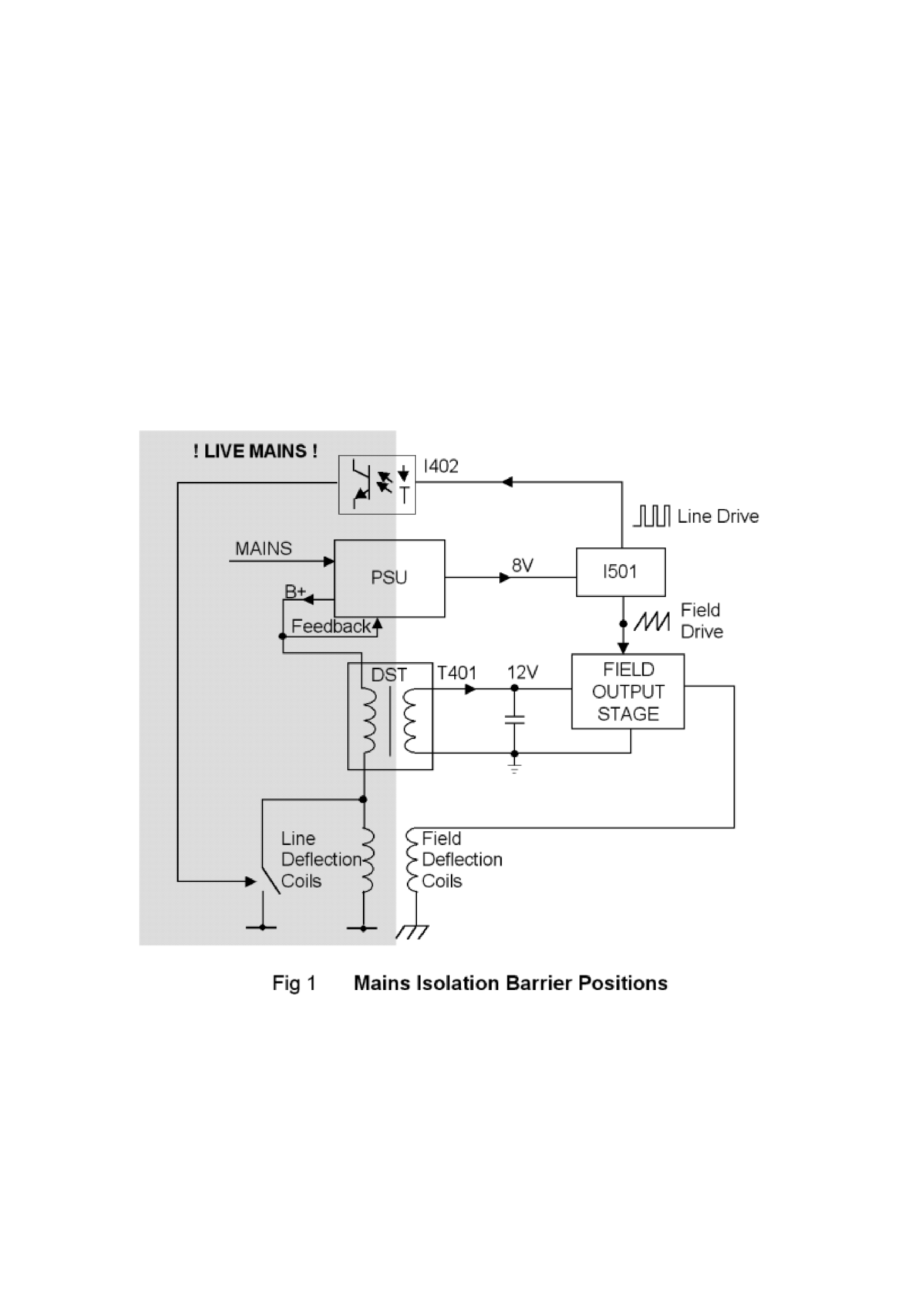
The Isolation Barrier
The chassis is a 'hot-coil' chassis whereby the line deflection coils are NOT isolated from the mains since the PSU does
not provide B+ rail isolation. Consequently, the mains isolation barrier is more convoluted than in a conventional
chassis and a much larger portion of the chassis is non-isolated. Figure 1 shows the isolation barrier position in the
chassis.
It can be seen that both the DST (T401) and the scan coils now straddle the isolation barrier and are, as such, safety
critical components. Also, the opto-coupler (I402) is required to pass line drive from I501 on the 'cold' side to the line
drive stage on the 'hot' side. The isolation barrier therefore consists of T802, T401, I402, C804, R804, R805, the scan
coils and 6mm air gaps. To maintain barrier integrity care should be taken not to reduce any air gaps, e.g. by protruding
wires, following component replacement. Deflection yoke lead dressing is important to maintain double insulation
across the isolation barrier. The position of the deflection lead sleeving is maintained by a tie wrap. Should this be
removed for any reason, the sleeving should be slid towards the deflection yoke and tie wrapped into position.
Semiconductor Device Handling Precautions
The chassis contains devices which may be damaged by static electrical charge during handling, particularly I501, I602,
I701 and Q801. To avoid damage, soldering irons should be earthed and service engineers should ideally wear wrist
straps earthed through a 1M resistor or at least discharge themselves to an earthed point.

5
SERVICING
Microprocessor Control System
Microcontroller
Micro-controller, I701, is either a SAA5288 (on non-teletext sets) or a SAA5290 (on teletext sets). Both
devices have integrated on-screen display (OSD) generator; the SAA5290 also has an integrated teletext
decoder. The micro-controller has a single 12MHz crystal X701.
The television is controlled by serial (I²C) bus communication, digital switching inputs and outputs, analogue-
to-digital inputs and pulse-width-modulation (PWM) outputs.
Reset
At power on, C709 is not charged so the voltage on pin 43 of the micro-controller rises with the 5V supply
and resets the micro-controller. An internal resistor to ground at this pin causes C709 to charge up and the
voltage on the reset pin to drop to 0V.
In normal operation, transistor Q702 is switched on and the reset pin is low, but if the 10V supply voltage
drops below about 8V the transistor will switch off and R721 will pull the reset pin high and reset the device.
User Control
User input is via infra-red remote control (Philips' RC5 protocol), internally decoded from the receiver I703,
or from three (non-matrixed) local control keys on active low inputs, I701 pins 18, 19 and 20. The LED
flashes each time a key is detected or remote command received.
Tuning
The tuning control voltage to the tuner is controlled via the PWM at pin 1 of I701 and integrating circuit
around Q001. Minimum voltage is at maximum mark-space ratio (bottom of each band). Band-switching is
controlled by active low outputs on pins 14, 15 and 16 (high, mid, low) and transistors Q002 to Q004. The
controller makes AFC corrections by reading on-tune information from I501 via the I²C bus.
As the tuner is controlled by voltage synthesis, there is no direct correlation between the controller output
and the tuned frequency.
Non-volatile memory
The non-volatile memory, I702, holds configuration information, user settings, parameters as applicable for
I²C controlled ICs and the programme tuning records. It is itself accessed by I²C.
When a new memory IC is fitted, the microcontroller will automatically load default information, which takes a
few seconds during power-up. Regular re-loading of the data, or corruption of settings may indicate I702 is
faulty.
AV switching
Inputs from pins 8 and 16 of SCART 1 are sampled by analogue to digital conversion on pins 9 and 10 of
I701 respectively. The input levels are adjusted such that the controller will automatically switch to AV1
when pin 8 is above 6V and RGB when pin 16 is above 1V. The time constant on pin 16 ensures the
controller will not detect real-time RGB insertion using pin 16.
OSD / Teletext
Line and field timings are obtained from V.sync on pin 37 and H.sync input on pin 36. Teletext (on teletext
sets only) is obtained from the CVBS input on pin 23. The RGB outputs on pins 34, 33 and 32 respectively
are inserted into the TV output when gated by the OSD EN OUT signal on pin 35. OSD / teletext contrast is
controlled by the peak reference level on pin 31, generated from the microcontroller PWM output on pin 2 via
Q305.
Error codes
Under the following fault conditions the television will switch to standby and flash the LED.