
TECHNICAL SPECIFICATIONS
TV System ............................. PAL/SECAM B,G
NTSC 3.58/4.43 MHz via Scart
Mains voltage........................210..240 V, 50Hz
Power consumption ................................135W
Standby power consumption ...................0.2W
Picture tube
2896 TAN,2896 TA
71cm
2996 TAN,2996 TA
74cm
Sound output (RMS) ..................... 2 x 10W/8
Connections
Front panel
Headphones
32..600
, 3.5mm
Audio/Video
Audio in: 0..2V (RMS)
Video in: 1V/75
Y/C in (SVHS)
Rear panel
A/V
Audio in: 0..2V (RMS)
Audio out: 0..2V/10k (RMS)
Video in/out: 1V/75
RGB in: 0.7V/75
(E1)
Y/C in: (SVHS)(E2)
Loudspeakers
min 10W/8
(RMS)
Aerial
75
Audio output
0..2V/10k (RCA)
SPÉCIFICATIONS TECHNIQUES
Systéme TV ...........................PAL/SECAM B,G
NTSC 3.58/4.43 MHz via Scart
Tension secteur.....................210..240 V, 50Hz
Consommation .......................................135W
Consommation en veille...........................0.2W
Tube-image
2896 TAN,2896 TA
71cm
2996 TAN,2996 TA
74cm
Sortie sonore (RMS)......................... 2 x 10W/8
Connexions
Sur le panneau avant
Ecouteurs
32..600
, 3.5mm
Audio/vidéo
Entrée audio:0..2V(RMS)
Entrée video: 1V/75
Entrée Y/C: (SVHS)
Sur le panneau arrière
Audio/video
Entrée audio:0..2V(RMS)
Sortie audio: 0..2V/10k (RMS)
Entrée vidéo/out: 1V/75
Entrée RGB: 0.7V/75
(E1)
Entrée Y/C: (SVHS)(E2)
Haut-parleurs
min 10W/8
(RMS)
Antenne
75
Sortie audio
0..2V/10k (RCA)
TECHNICAL SPECIFICATIONS
TV-Norm................................PAL/SECAM B,G
NTSC 3.58/4.43 MHz via Scart
Netzspannung.......................210..240 V, 50Hz
Leistungsaufnahme.................................135W
Leistungsaufnahme im standby-modus...0.2W
Bildröhre
2896 TAN,2896 TA
71cm
2996 TAN,2996 TA
74cm
Tonleistung (RMS)......................... 2 x 10W/8
Anschlüsse
An der Vorderseite
Kopfhörer
32..600
, 3.5mm
Audio/Video
Audio ein: 0..2V (RMS)
Video ein: 1V/75
Y/C ein (SVHS)
An der Rückseite
Audio/video
Audio ein: 0..2V (RMS)
Audio aus: 0..2V/10k (RMS)
Video ein/aus: 1V/75
RGB ein: 0.7V/75
(E1)
Y/C ein: (SVHS)(E2)
Lautsprecher
min 10W/8
(RMS)
Antenne
75
Audio-Ausgang
0..2V/10k (RCA)
December 1998
No. 0103
CP2896TA
CP2896TAN
CP2996TA
CP2996TAN
SERVICE MANUAL
MANUEL D'ENTRETIEN
WARTUNGSHANDBUCH
CAUTION:
Before servicing this chassis, it is important that the service technician read
the "Safety Precautions"and "Product Safety Notices"in this service manual.
ATTENTION:
Avant d'effectuer l'entretien du châassis, le technicien doit lire les
«Précautions de sécurité» et les «Notices de sécurité du produit» présentés
dans le présent manuel.
VORSICHT:
Vor Öffnen des Gehäuses hat der Service-Ingenieur die ,,Sicherheitshinweise"
und ,,Hinweise zur Produktsicherheit"in diesem Wartungshandbuch zu lesen.
Data contained within this Service
manual is subject to alteration for
improvement.
Les données fournies dans le
présent
manuel
d'entretien
peuvent
faire
l'objet
de
modifications
en
vue
de
perfectionner le produit.
Die in diesem Wartungshandbuch
enthaltenen
Spezifikationen
können
sich
zwecks
Verbesserungen ändern.

42
G Contents
Repair instructions ..................................................................................................................................................................... 1
Technical data ............................................................................................................................................................................. 2
Block diagrams ........................................................................................................................................................................... 3
SCART connector ....................................................................................................................................................................... 6
Operating instructions ............................................................................................................................................................... 7
Initialization of NVRAM .............................................................................................................................................................. 7
Service adjustments ................................................................................................................................................................... 9
Schematic diagrams ................................................................................................................................................................ 19
Variable components ............................................................................................................................................................... 30
Spare parts ................................................................................................................................................................................ 31
D Inhaltsverzeichnis
Reparatur-Anweisung ................................................................................................................................................................ 1
Technische Daten ....................................................................................................................................................................... 2
Blockschaltbilden ....................................................................................................................................................................... 3
SCART-Anschluß ........................................................................................................................................................................ 6
Bedienungsanleitung ............................................................................................................................................................... 11
Initialisierung des NVRAM ...................................................................................................................................................... 11
Service-Einstellungen .............................................................................................................................................................. 12
Schaltpläne ............................................................................................................................................................................... 19
Röhrenabhängige Bauteile ...................................................................................................................................................... 30
Ersatzteileliste ........................................................................................................................................................................... 31
F Contenu
Instructions de reparation ......................................................................................................................................................... 1
Données téchniques ................................................................................................................................................................... 2
Diagrammes des blocs .............................................................................................................................................................. 3
Connecteur SCART ..................................................................................................................................................................... 6
Mode d'emploi ......................................................................................................................................................................... 15
Initialisation de la NVRAM ....................................................................................................................................................... 15
Réglages de service ................................................................................................................................................................. 16
Schéma ..................................................................................................................................................................................... 19
Composants variables ............................................................................................................................................................. 30
Pièces de rechange .................................................................................................................................................................. 31

1
G Repair instructions
Service and repair work must be performed only in
accordance with existing safety regulations!
Where a high current or mechanical stress exists solder
connections have been strengthened by using eyelets. Such a
connection must not be left without an eyelet.
Wiring has an effect on safety and EMC (Electro-Magnetic
Compatibility). Therefore wires must be maintained in their
original positions.
X-RAY REGULATIONS:
The picture tube type and the maximum permissible high-
voltage ensure that the X-ray intensity of the receiver remains
far below the permissible value. The high-voltage must not
exceed the value mentioned on the type label. The high
voltage is within the permissible limits when the operating
voltage (U1) of the horizontal deflection stage is accurate.
Refer to the section "Service adjustments".
ESD Warning
The receiver contains components that are sensitive to
electrostatic discharge (ESD). Any servicing or repair work
must be done in an environment where the components will
not be subjected to ESD. Use a special grounding device!
D Reparatur-Anweisung
Bei Reparaturen gültige Sicherheitsvorschriften beachten!
Lötverbindungen die einem hohen Stromfluß oder starker
mechanischer Beanspruchung unterliegen wurden durch
Lötösen verstärkt. Eine derart belastete Lötverbindung darf
nicht ohne Lötöse verbleiben.
Die Lage der Kabel hat einen Einfluß auf die Betriebssicherheit
und das EMV Verhalten (Elektro Magnetische Verträglichkeit)
des Geräts. Aus diesem Grund müssen die Kabel in ihrer
orginalen Position verbleiben.
RÖNTGENVERORDNUNG:
Der Bildröhrentyp und die maximal zulässige Hochspannung
stellen sicher, daß die Röntgenstrahlenintensität des
Fernsehgerätes weit unter dem zulässigen Wert bleibt. Die
Kathodenhochspannung darf den auf dem Typenschild
angegebenen Wert nicht überschreiten. Die Hochspannung
liegt im zulässigen Bereich, wenn die Betriebsspannung (U1)
der Horizontal-Ablenkstufe genau eingehalten wird. Siehe
auch Abschnitt "Service-Einstellungen".
EGB-Warnung
Das Fernsehgerät enthält Bauteile, die empfindlich auf
elektrostatische Entladung reagieren. Alle Service- oder
Reparaturarbeiten sind in einer Umgebung durchzuführen, in
der die Bauteile nicht elektrostatischer Entladung ausgesetzt
sind. Verwenden Sie eine spezielle Erdungsvorrichtung!
F Instructions de reparation
Veuillez observer les prescriptions de sécurité en viguer lors
de dépannage !
Les connections par soudure doivent être consolidées par des
oeillets lorsqu'elles sont soumises à des tensions importantes
et à des contraintes mécaniques. De telles connections
doivent toujours être faites à l'emplacement d'un oeillet.
Le câblage a un effet sur la sécurité et les perturbations
électromagnétiques. Pour cette raison les câbles doivent
garder leur position originale.
REGLEMENTATIONS RELATIVES AUX RAYONS X:
Le type du tube image et la haute tension maximale autorisée
garantissent une intensité des rayons X du récepteur
largement en deçà de la valeur autorisée. La tension ne doit
pas dépasser la valeur indiquée sur la plaquette signalétique.
La haute tension reste dans la fourchette autorisée lorsque la
tension de sevice (U1) du niveau de déflexion horizontale est
précise. Reportez-vous à la section "Réglages de service".
Avertissement DES
Le récepteur contient des composants qui sont sensibles aux
décharges électrostatiques (DES). Toute opération de
maintenance ou de réparation doit être effectuée dans un
environnement où les composants ne seront pas exposés à
des décharges électrostatiques. Utilisez un dispositif de mise à
la terre spécial !

2
Technical data
System
NTSC
Mains power
Consumption 1)
In stand-by
Frequency range
Sound output (RMS)
Subwoofer 2)
Connections on the front
panel
Headphones
Audio/Video
Connections on the rear
panel
Audio/Video
External loudspeakers
Antenna
Audio output 2)
Specifications are subject
to change.
1) Depends on option
modules and picture tube.
2) Not in all models.
Technische Daten
Norm
NTSC
Netzanschluß
Leistungsaufnahme 1)
Im Bereitschaft
Frequenzbereich
Tonendstufe (RMS)
Subwoofer 2)
Anschlüsse an der
Vorderseite
Kopfhöreranschluß
Audio/Video
Anschlüsse an der
Rückseite
Audio/Video
Externe Lautsprecher
Antennenanschluß
Audio Ausgang 2)
Änderungen vorbehalten
1) Abhängig von
Optionsmodulen und
Bildröhre.
2) Nicht in allen Modellen.
Données téchniques
Systéme
NTSC
Alimentation
Consommation 1)
En mode veille
Gamme de fréquences
Sortie sonore (RMS)
Subwoofer 2)
Connexions sur le
panneau avant
Ecouteurs
Audio/Vidéo
Connexions sur le
panneau arrière
Audio/Vidéo
Haut-parleurs externes
Antenne
Sortie audio 2)
Les Spécifications
peuvent êt re modifiées
sans préavis.
1) Dépend des modules
option-nels et du tube
cathodique.
2) Pas sur tous les modèles.
PAL/SECAM B, G
3.58/4.43 MHz via Scart
210...240 V, 50 Hz
135 W (normal)
0.2 W
48.25 - 855.25
2 x 10 W/8
14 W/16
32...600 , 3.5 mm
Audio in: 0...2 V (RMS)
Video in: 1 V/75
Y/C in (SVHS)
Audio in: 0...2 V (RMS)
Audio out: 0...2 V/10 k
(RMS)
Video in/out: 1 V/75
RGB in: 0.7 V/75 (E1)
Y/C in (SVHS) (E2)
min 10 W/8 (RMS)
75
0...2 V/10 k (RCA)
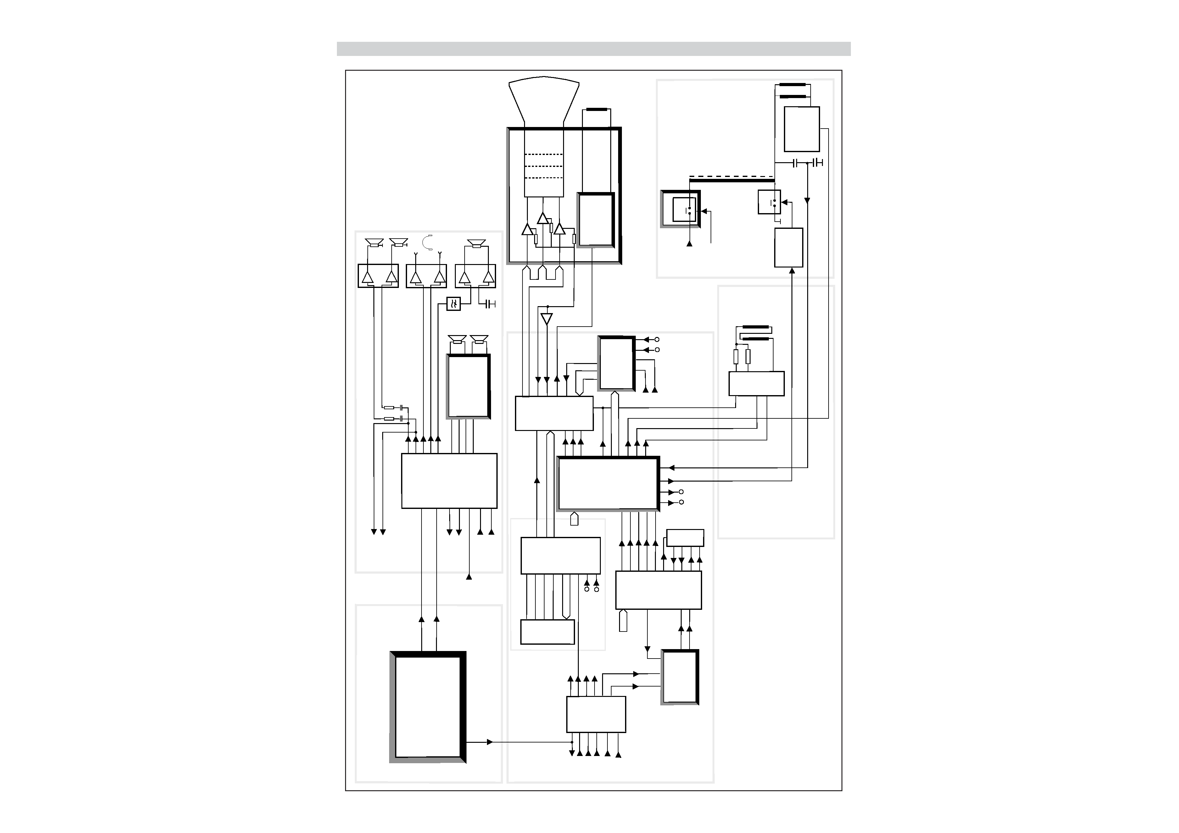
3
Block
diagram,
signal
routes
15
20, 22, 24
19
10-12
13
fb
2-4
1
fb
bcl
BC
8
6
7
ICt1
ICr2
44-46
18-27
ICr1
47
BLAN
14
13
12
Y
ICd1
25
26
V
U
ICd3
4
2
3
1
RGB + fb
17
18
16
15
14
C
CVBS/Y
C
ICq1
OUT
OUT
13
3
11 IN
IN
CVBS/Y
5, 6
IN
8, 10
IN
2H 2V
14
sc
17
11
HA
VA
10
SSc
D1
D0
D2
D3
32
33
34
35
I/O2
I/O1
I/O3
I/O4
2
1
24
25
9
CVBS
3
2V
4
2H
A0-A9
RGB
ICs1
Mk1
DATA IN
DATA OUT
WS
L
R
CL
L, R
L, R
L, R
AM
SIF
R, L
R, L
L
R
3D/Pro Logic
module
AR7xx
4
6
1
7
ICa1
29
28
26
25
9
1
ICa2
2
6
33, 34
36, 37
46, 47
49, 50
52, 53
55
60
14
13
12
11
5
6
7
8
SOUND BLOCK
CRT module
HH7xx
ICh3
ICh2
ICh1
R
G
B
6
5
4
9
7
BC
SVM
module
VMxxx
PIP
module
PP7xx
RGB
RGB
IQTV2
&
DPLL
DB7xx
Flyback
EW
Ver
Ver
Hor
sc
11
14
12
16
Comb filter
module
CF7xx
V
Y
U
11
10
67
13
15
14
18-21
Scart 1
34
35
33
37
38
Camera
Scart 2
Scart 1
RF BLOCK
PIP
module
10
9
C
CVBS/Y
11 12
Scart 2
Scart 2
RGB
2H 2V
27 26
24
TELETEXT
VIDEO BLOCK
Adjustable
audio
Scart 1
Camera
Scart 3
VGA
Scart 2
Scart 1
17
Y
Tk3
SWxxx
U1
12V
22 17
20
19
18
12
11
1
9
2
Scart 1
26
Y
SVM coil
Diode
modulation
Dk7, Dk8
Tk4,ts1,ts2
5
Vertical
deflection
yoke
Horizontal
deflection
yoke
Line
driver
Tk1, Tk2
Vertical
deflection
and
E-W driver
Horizontal
deflection
5,9-12,14-18
MSP3410D
Audio
processor
TDA9143
Colour
decoder
TDA4780
RGB processor
SDA5275S
Megatext
514400
Text memory
TEA6417
Video switch
TDA8354
Vertical output
TDA2616
Audio power
amplifier
TL082
Headphone
amplifier
TV-Frontend
Tuner+IF
19
18
20
PIP
CVBS
1
Scart 3
IN
IN
23
1
Fsc
clock
VGA
VGA/RGB
5
6
4
ICa4
1
9
TDA2616
Active subwoofer
amplifier
ICa3
31
SUB