SPECIFICATIONS AND PARTS ARE SUBJECT TO CHANGE FOR IMPROVEMENT.
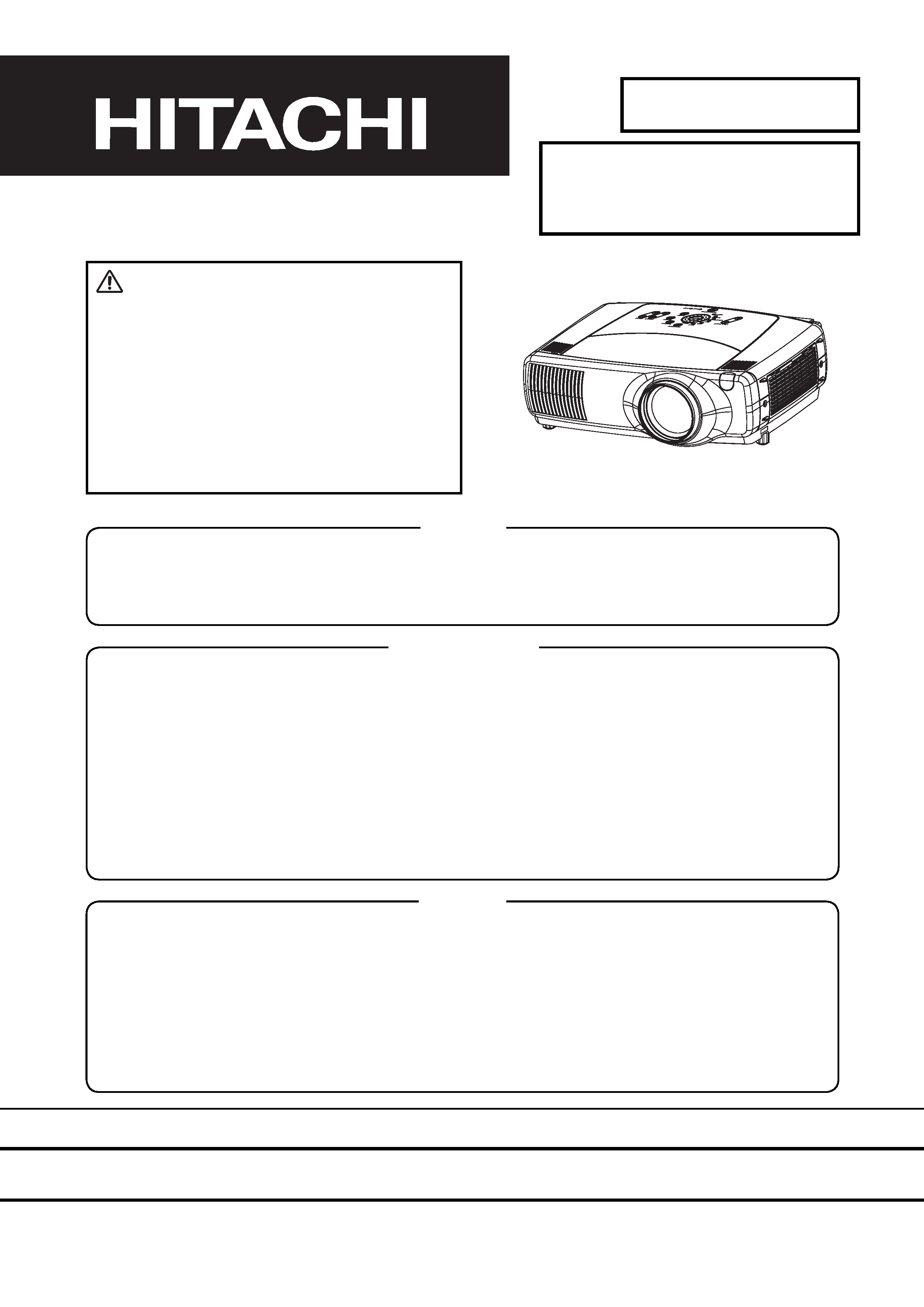
Multimedia LCD Projector
March 2004 Digital Media Division
SM0542
SERVICE MANUAL
Be sure to read this manual before servicing. To assure safety from fire, electric shock, injury, harmful radi-
ation and materials, various measures are provided in this Hitachi Multimedia LCD Projector. Be sure to
read cautionary items described in the manual to maintain safety before servicing.
Caution
1. When replace the lamp, to avoid burns to your fingers. The lamp becomes too hot.
2. Never touch the lamp bulb with a finger or anything else. Never drop it or give it a shock. They may
cause bursting of the bulb.
3. This projector is provided with a high voltage circuit for the lamp. Do not touch the electric parts of
power unit (main), when turn on the projector.
4. Do not touch the exhaust fan, during operation.
5. The LCD module assembly is likely to be damaged. If replacing to the LCD LENS/PRISM assembly, do
not hold the FPC of the LCD module assembly.
6. Use the cables which are included with the projector or specified.
Service Warning
1. Features --------------------------------------------------- 2
2. Specifications--------------------------------------------- 2
3. Names of each part ------------------------------------- 3
4. Adjustment ------------------------------------------------ 5
5. Troubleshooting---------------------------------------- 12
6. Service points ------------------------------------------ 18
7. Wiring diagram ----------------------------------------- 29
8. Disassembly diagram--------------------------------- 36
9. Replacement parts list-------------------------------- 39
10.RS-232C communication ---------------------------- 40
11.Block diagram------------------------------------------- 50
12.Connector connection diagram -------------------- 51
13.Basic circuit diagram---------------------------------- 52
Contents
Warning
The technical information and parts shown in this
manual are not to be used for: the development,
design, production, storage or use of nuclear, chemical,
biological or missile weapons or other weapons of
mass destruction; or military purposes; or purposes that
endanger global safety and peace. Moreover, do not
sell, give, or export these items, or grant permission for
use to parties with such objectives. Forward all inquiries
to Hitachi Ltd.
CP-X1200W(P5XLA)
CP-X1250W(P5XMLA)
CP-X1200WA(P5XMLB)
2
CP-X1200(P5XLA) / CP-X1250(P5XMLA) / CP-X1200WA(P5XMLB)
1. Features
Ultra high brightness
Whisper mode equipped
User memory function
CP-X1200
CP-X1250
CP-X1200WA
Liquid
Crystal
Panel
Drive system
TFT active matrix
Panel size
2.5cm (0.99inches)
Number of pixels
1024 (H) × 768 (V)
Lamp
310W
275W
RGB signal
input
RGB IN
D-sub
15pin
Video: Analog 0.7Vp-p, 75 terminator
H/V. sync.: TTL level (positive/negative)
Composite sync.: TTL level
BNC
Digital
input
MI-D
Type: T.M.D.S
Amplitude differential signal: DC: 150~1200mV AC: 1.56Vp-p
AUDIO IN
1
200mVrms, 57k
Stereo mini jack
2
Video signal
input
COMPOSITE
VIDEO
System
NTSC, NTSC4.43, PAL (BGDHI), SECAM, PAL-M, PAL-N, PAL60
1.0Vp-p, 75 terminator
RCA jack
S-VIDEO
Y
1.0Vp-p, 75 terminator
C
0.3Vp-p, 75 terminator
Mini DIN 4-pin jack
COMPONENT
VIDEO
System
525i (480i), 525p (480p), 625i (575i), 720p, 1080i
Y
1.0Vp-p, 75 terminator
RCA jack ×3, BNC ×3
CB/CR
0.7Vp-p, 75 terminator
PB/PR
0.7Vp-p, 75 terminator
AUDIO IN
L
200mVrms, 57k (max. 3.0Vp-p)
RCA jack ×2
R
Signal output
RGB OUT
Video: Analog 0.7Vp-p, 75 output impedance (positive)
H/V. sync.: TTL level (positive/negative)
Composite sync.: TTL level
D-sub 15-pin shrink jack
AUDIO OUT
0~200mVrms, output impedance 1k
Stereo mini jack
DC OUT
5V/1A (Power supply for the Wireless unit)
Speaker output
1.0W + 1.0W(stereo)
Power supply
AC100~120V / 5.2A , AC220~240V / 2.2A
AC100~120V / 4.7A , AC220~240V / 2.0A
Power consumption
470W
430W
Dimensions
420(W) × 150(H) × 310(D) mm (No including protruding parts)
Weight
7.7kg (17lbs)
Temperature
Operation : 0~35°C
Storage : -20~60°C
Accessories
Remote control transmitter × 1
MI-D cable × 1
Power cord × 3
Battery × 2
RGB cable × 1
User's manual 1 (with safety instructions) × 1
AV cable × 1
User's manual 2 (Book or CD-ROM) × 1
Partial magnification function
Keystone distortion correction
Optical lens shift
2. Specifications
3
CP-X1200(P5XLA) / CP-X1250(P5XMLA) / CP-X1200WA(P5XMLB)
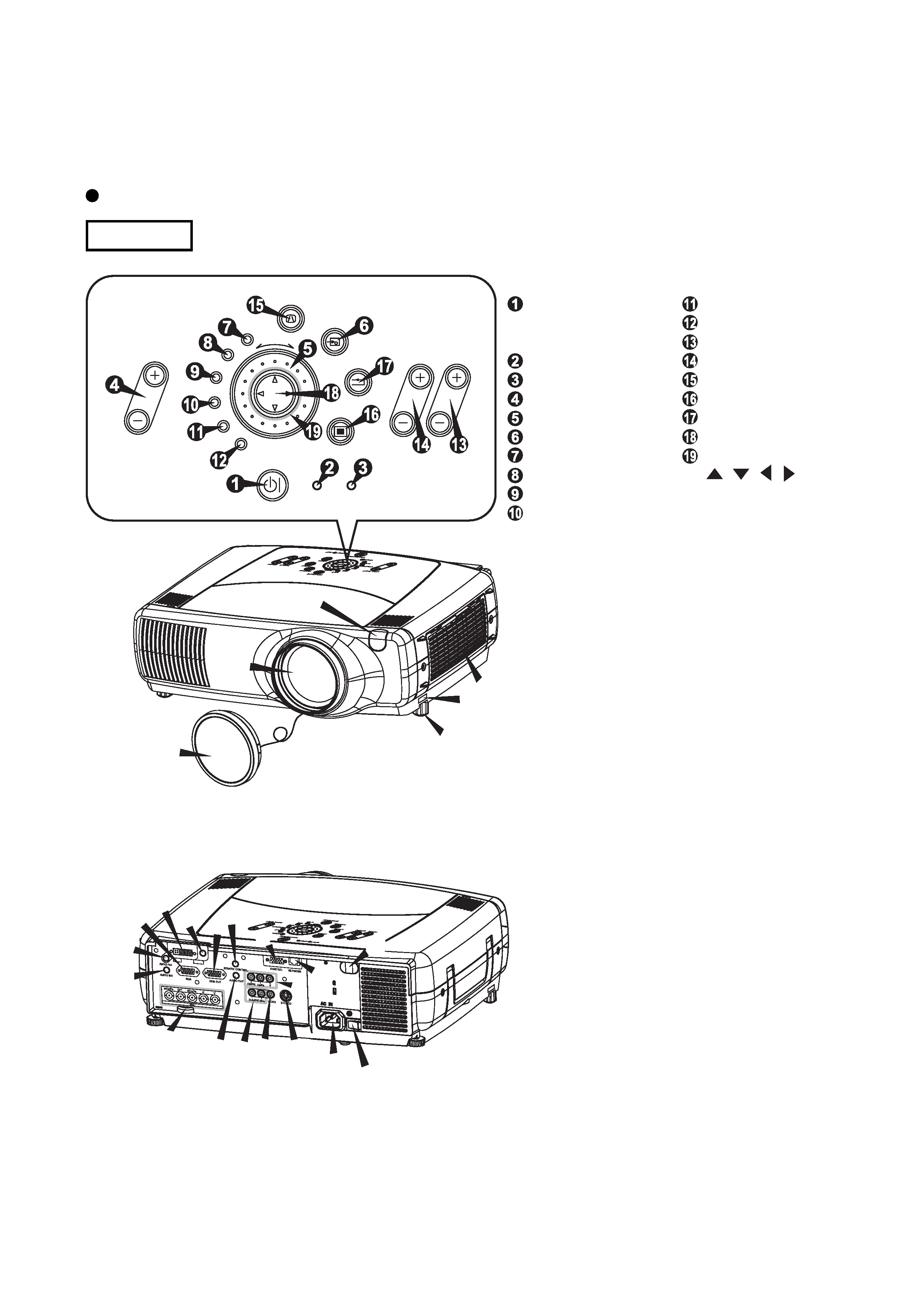
3. Names of each part
Parts names
Projector
1 Elevator button
2 Elevator foot
3 Remote sensor
4 Lens cap
5 Lens
The picture is projected from
here.
6 Filter cover
An air filter is inside.
A RGB port
B M1-D port
C BNC port
D AUDIO IN 1 port
E AUDIO IN 2 port
F CONTROL port
G NETWORK port
H AUDIO IN R/L port
I
VIDEO IN port
J S-VIDEO port
K COMPONENT port
L RGB OUT port
M AUDIO OUT port
7 REMOTE CONTROL port
8 DC OUT port
9 AC Inlet
10 Power switch
Projector (Front/Right)
Projector (Rear/Left)
1
2
3
5
6
4
9 10
ENTER
INPUT
M1-D
RGB
BNC
S-VIDEO
STANDBY/ON
TEMP
VIDEO
COMPONENT
LAMP
KEYSTONE
SEARCH
RESET
MENU
FOCUS
LENS SHIFT
ZOOM
Control Panel
STANDBY/ON button
and STANDBY/ON
indicator
TEMP indicator
LAMP indicator
LENS SHIFT buttons
INPUT dial
SEARCH button
M1-D indicator
RGB indicator
BNC indicator
COMPONENT indicator
S-VIDEO indicator
VIDEO indicator
ZOOM buttons
FOCUS buttons
KEYSTONE button
MENU button
RESET button
ENTER button
Cursor buttons
//
/
3
L
A
D
E
C
H I
B
M
J
K G
8
7
F
4
CP-X1200(P5XLA) / CP-X1250(P5XMLA) / CP-X1200WA(P5XMLB)
STANDBY/ON
VIDEO
LASER INDICATOR
ESC
MENU
POSITION
RESET
AUTO
KEYSTONE
1 2 3
ID CHANGE
SEARCH
ON
OFF
FREEZE
MUTE
MAGNFY
PinP
VOLUME
RGB
BLANK
PREVIOUS
NEXT
ASPECT
MOUSE
LASER
LENS SHIFT
+
++
FOCUS
ZOOM
1
4
14
19
16
27
29
31
32
33
15
13
20
21
22
23
25
24
28
17
30
34
35
6
26
36
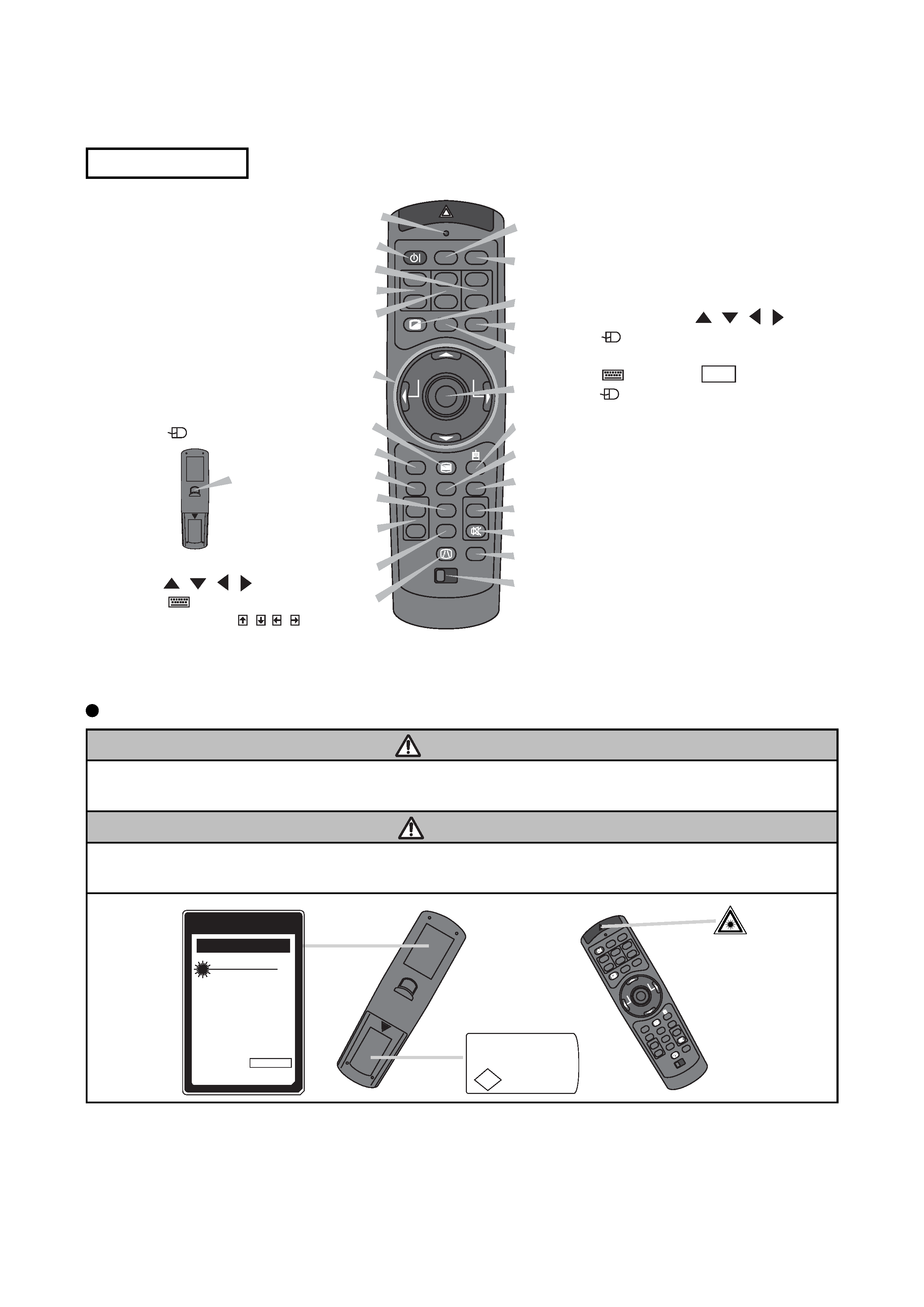
Remote Control
20 LASER INDICATOR
21 VIDEO button
22 RGB button
23 BLANK button
24 ASPECT button
25 LASER button
26 Cursor buttons
/
/
/
(
Mouse move pointer)
27 ESC button
(
Keyboard ESC key)
28 (
Mouse right button)
29 POSITION button
30 AUTO button
31 PinP button
32 MAGNIFY buttons
33 FREEZE button
34 VOLUME button
35 MUTE button
36 ID CHANGE switch
1 STANDBY/ON button
4 LENS SHIFT buttons
6 SEARCH button
13 ZOOM buttons
14 FOCUS buttons
15 KEYSTONE button
16 MENU button
17 RESET button
18 ENTER button
(
Mouse left button)
19 Cursor buttons
//
/
(
Keyboard
Arrow keys
///)
18
(Rear)
Remote control
This remote control has a laser pointer in place of a finger or rod. The laser beam works and the LASER
INDICATOR lights while the LASER button is pressed.
About the Laser pointer
WARNING
· The laser pointer of the remote control is used in place of a finger or rod. Never look directly into the laser
beam outlet or point the laser beam at other people. The laser beam can cause vision problems.
CAUTION
· Use of controls or adjustments or performance of procedures other than those specified herein may result in
hazardous radiation exposure.
STANDBY/ON
VIDEO
LA
SER
INDICA
TO
R
ESC
MENU
POSITION
RESET
AUT
O
KEYST
ONE
1 2
3
ID
CHANG
E
SEA
RCH
ON
OFF
FREEZE
MUTE
MA
GNFY
PinP
VOLU
ME
RG
B
BLANK
PREVIOUS
NEXT
ASPEC
T
ENTER
LASER
LENS
SHIFT
+
++
FO
CUS
ZO
OM
JQA MADE IN CHINA
P S
C
INTERLINK ELECTRONICS
AVOID EXPOSURE-LASER
RADIATION IS EMITTED
FROM THIS APERTURE
CA UTION
WAVE LENGTH: 640-660nm
MAX OUTPUT: 1mW
CLASS 2 LASER PRODUCT
Comples with 21 CFR, 1040.10 AND 1040.11
IEO60825-1:1993+A1:1997+A2:2001
LASER-STRAHLING
NICHT IN DEN STRAHL BLICKEN
LASER KLASSE 2
WAVE LENGTH:640-660nm MAX OUTPUT:1mW
MODEL:H-IRC4
LASER RADIATION
DO NOT STARE INTO BEAM
MANUFACTURER:
B
MANUFACTURED
JANUARY,2003
INTERLINK K.K.
1-10-7 HIGASHIKANDA CHIYODA-KU,TOKYO,JAPAN
101-0031
MADE IN CHINA
5
CP-X1200(P5XLA) / CP-X1250(P5XMLA) / CP-X1200WA(P5XMLB)
4. Adjustment
4-1 Before adjusting
4-1-1 Selection of adjustment
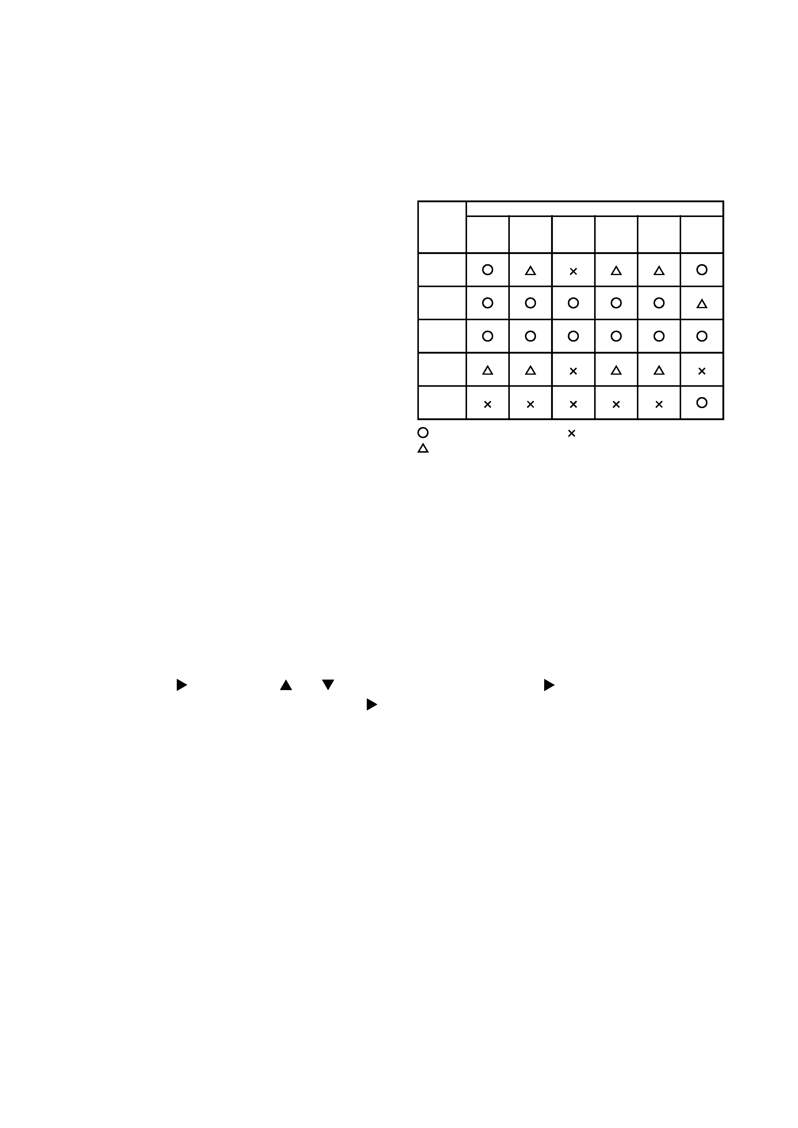
When any parts in the table 4-1 are changed, choose
the proper adjusting items with the chart.
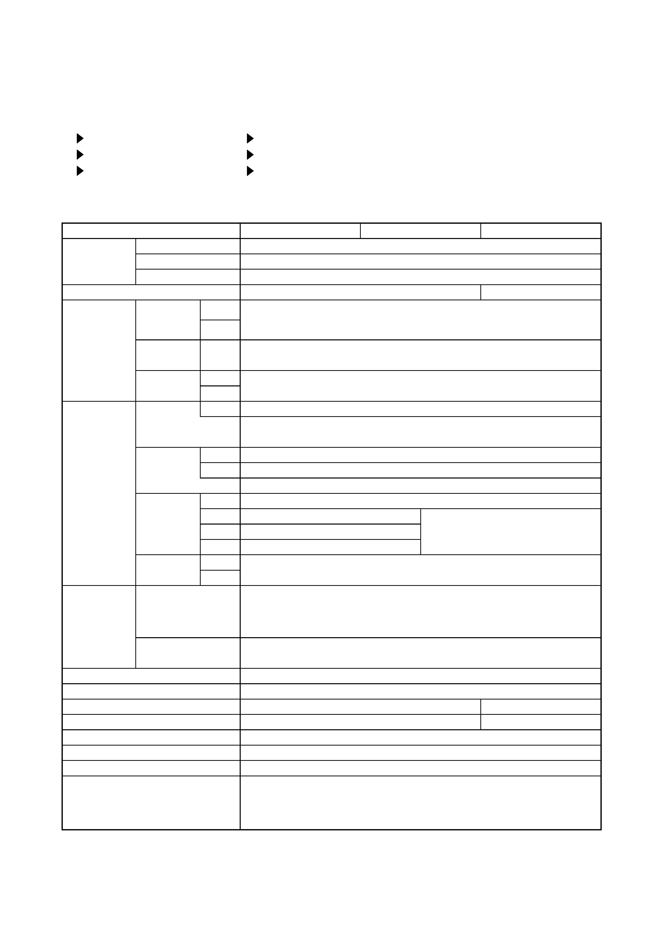
Table 4-1: Relation between the replaced part and adjustment
Replaced
part
Adjustment
Ghost
(Chap.4-2)
Flicker
(Chap.4-3)
NRSH
(Chap.4-4)
White
balance
(Chap.4-5)
Color
uniformity
(Chap.4-6)
AIR
FILTER
(Chap.4-7)
Dichroic
optics unit
LCD/LENS
prism
assembly
PWB
assembly
Drive
Lamp
unit
assembly
PWB
assembly
Dust sensor
: means need for adjustment.
: means not need for djustment.
: means recommended.
4-1-2 Setting of condition before adjustment
1. Before starting adjustment, warm up the projector
for about 10 minutes.(Blank white)
2. Set Zoom Wide to Max. And project an image
with more than 1m (40 inches) in diagonal size.
3. Shift the Lens to the highest position with the
[LENS SHIFT +] button.
4. Normalizing the video adjustment.
(Press the [MENU] button of the Remote control
transmitter to display the MAIN menu. After
pressing the [ ] key, use the [ ] or [ ] key to
select [RESET]. Reset menu will appear by the [ ]
key, then choose [EXECUTE]. Next, open the
PICTURE1 menu. Choose RESET and perfom
EXECUTE by the same operation described above.
*note :The MAIN and PICTURE1 menu is not
reset with no signal.
5. Set the NORMAL at GAMMA in the PICTURE1 menu.
6. Perform all adjustments from the FACTORY MENU.
Perform the following operations to display the
FACTORY MENU.
a. Press the [MENU] button on the Remote control
transmitter (the MAIN menu will appear).
b. Select the [RESET] in the MAIN menu, and
then press the [ ] button.
c. Next, press the [RESET] button one time. And
hold the [RESET] button for 3 seconds or
more (the FACTORY MENU will appear).