Hitachi Plasma Screen Tilting Wall-mount Unit
Model
CMPAK345
Installation Instructions
Thank you for purchasing the Hitachi Plasma Screen Wall-mount Unit.
To ensure correct usage, please read this instruction manual thoroughly. After reading, please store this
manual in a safe place for future reference.
This plasma screen wall-mount unit is for use only with the following models:
HITACHI Plasma Screens: CMP307XE, CMP4121, CMP42PMA400E, CMP4202E, CL42PD2100,
42PD3000 & CMP5000WXE.
SUPPORTING VISION LTD
Manufactured in the UK
TEL: 0845 6023109
FAX: 01283 792300
E-mail: [email protected]
MOUNTING INSTRUCTIONS
CONSULT AUTHORIZED SERVICE PERSONNEL FOR THE INSTALLATION OF THIS UNIT.
I
NSTRUCTIONS MUST BE FOLLOWED PRECISELY FOR SAFE AND STABLE INSTALLATION.
SUPPORTING VISION LTD ARE NOT LIABLE FOR ANY DAMAGE OR INJURY CAUSED BY
MISHANDLING OR IMPROPER INSTALLATION.
Features
·
Suspension system allows quick and easy
installation.
·
Flat Installation 22mm distance, wall to rear of
P
lasma display
·
Tilt 0 to 10 degrees.
·
Width adjustment 30mm side to side screen
movement.
·
Cable access Pull bottom of screen away from
wall for Plasma connection access.
·
Security bolt Prevents removal of screen after
installation.
INSTALLATION
Installation of this unit should be carried out by
qualified technicians. Install in an appropriate
location only after checking wall structure and
durability for accident prevention. Consult a
qualified builder if in any doubt of wall structural
integrity
.
Wall Bracket for HITACHI Plasma Screen Models: CMP307XE, CMP4121,
CMP42PMS400E, CMP4202E, CL42PD2100, 42PD3000, CMP5000WXE.
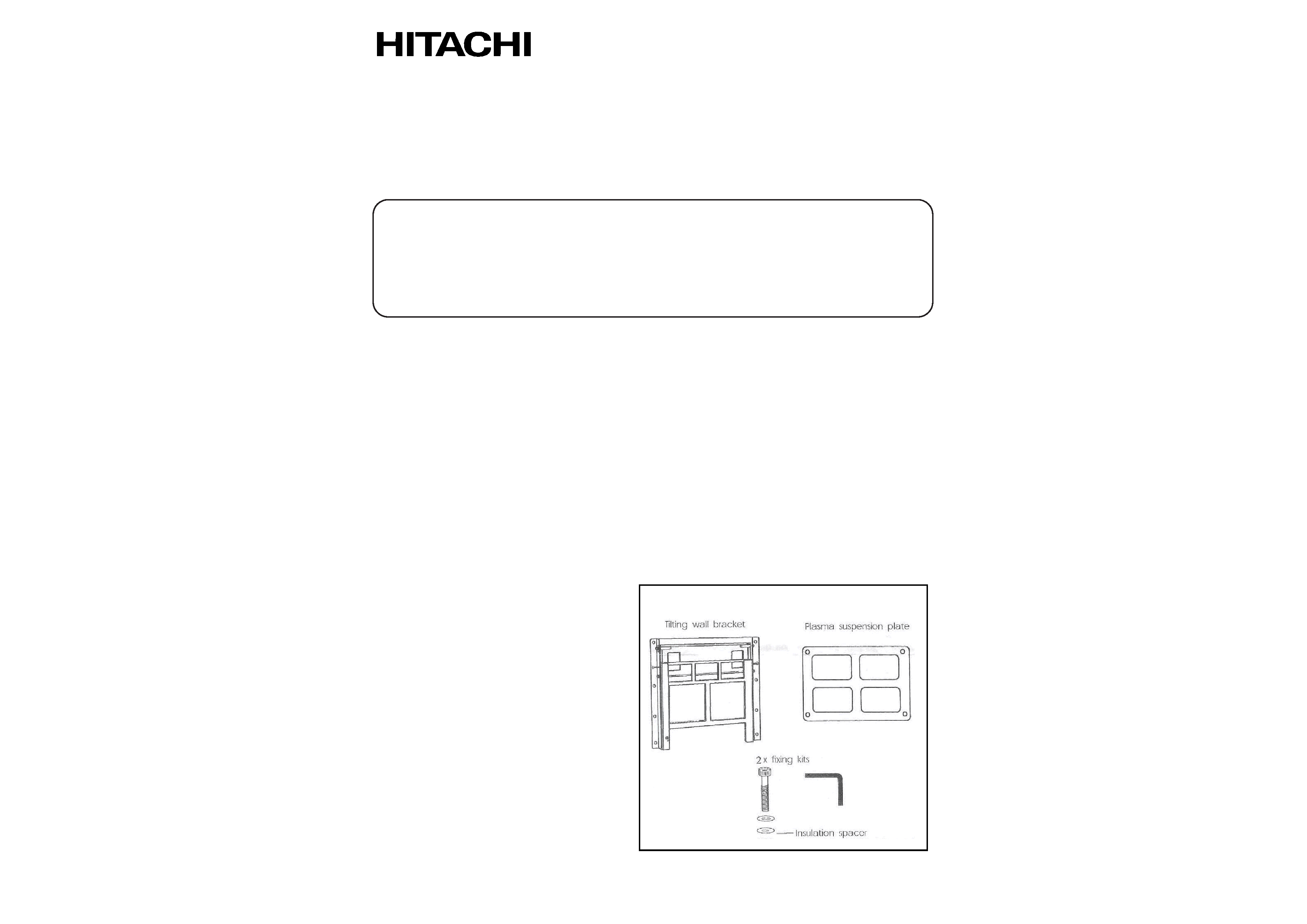
List of Components

1. MOUTING WALL PLATE
Mount the wall plate on the wall using screws and/or bolts appropriate to wall construction (if in
doubt consult a qualified builder). Locate screws and/or bolts through all 8 holes (Fig. 1).
2. ATTACHING SUSPENSION PLATE TO PLASMA DISPLAY
Attach the suspension plate (Fig. 2) to rear of the Plasma screen using screws/washers/isolators
appropriate to model of the Plasma screen.
Refer to Fig. 2A for location holes relating to make and model of the Plasma Screen. Tighten screws
with hex head key supplied.
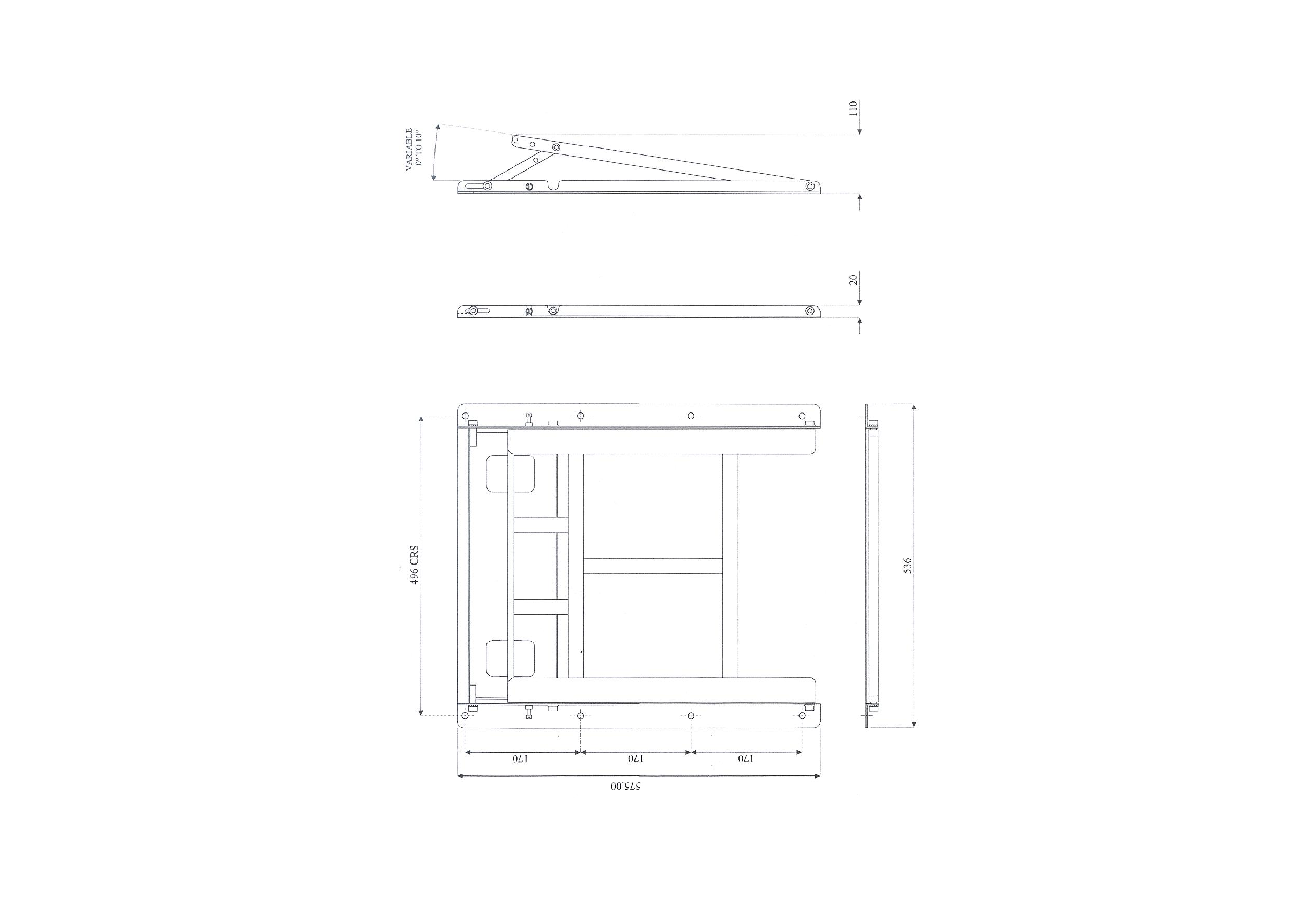
3. SCREEN ANGLE ADJUST - FLAT OR TILT?
Determine the amount of screen tilt required (0 to 10 degrees)
Adjust accordingly, loosening the angle adjustment socket screw (Fig. 1) to secure tilt plate
(Fig. 1) in preferred position.
For a flat 0 degree installation, lock the tilt plate into position by fastening cheese-head screws to
their maximum through locator holes on tilt plate.
Tighten angle adjustment screws - both sides (Fig. 1).
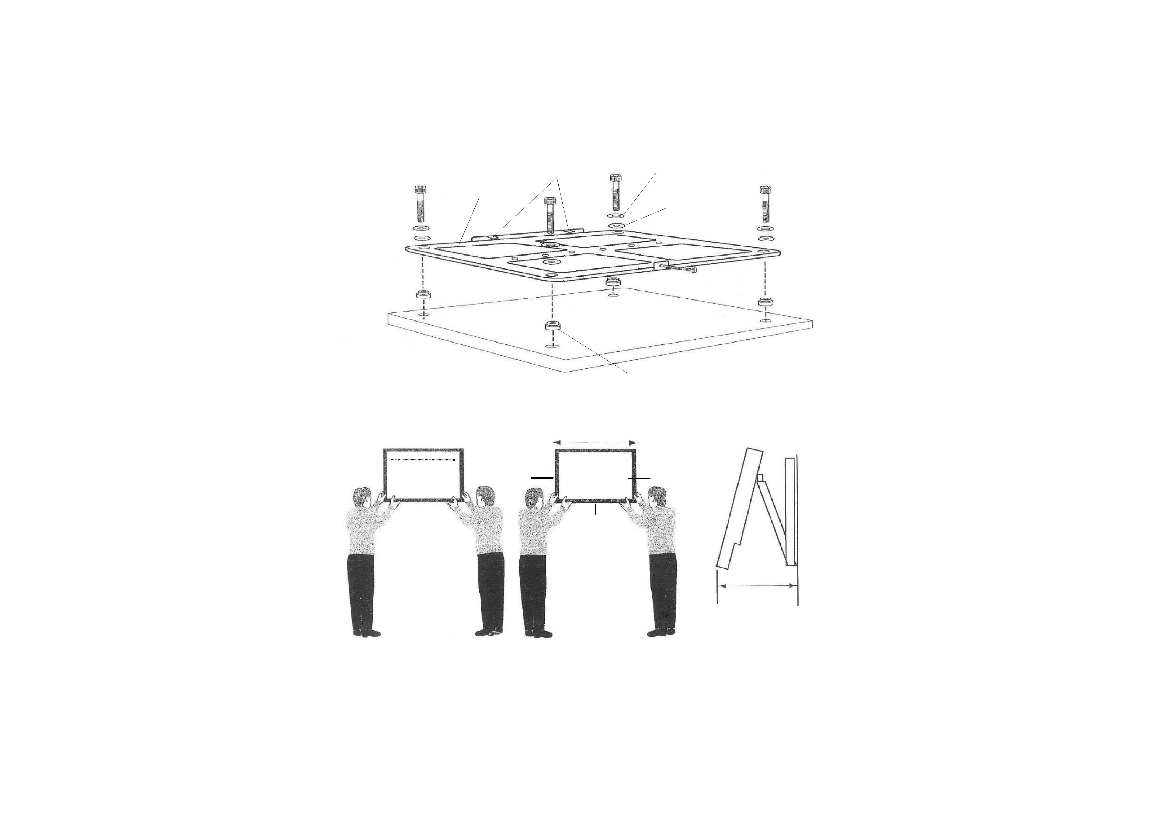
4. ENGAGING PLASMA/SUSPENSION PLATE WITH WALL BRACKET
Minimum two fit persons required
Lift the Plasma display to engage (Fig. 3) the two suspension hooks (Fig. 2) over suspension bar
(Fig. 1). The suspension bar is highlighted on the wall bracket by an orange sticker.
The screen is now suspended.
5. WIDTH ADJUSTMENT
The screen and the suspension plate can now be moved within a range of 3cm side-to-side on the
suspension bar (Fig. 4). This is to allow a flush-fitting location of multiple screens side-to-side or for
Plasma-wall installations.
6. CABLE CONNECTION
The Plasma display cable connections can now be accessed by pulling the bottom edge of the
display with the suspension plate away from the wall, as shown in Fig. 5.
7. SECURITY
Finally, using a screwdriver, fasten the silver M6/60 security bolt now accessed at the centre bottom
of the screen/suspension plate. When tightened, this will locate behind wall plate strap
(Figs. 1 and 5).
SCREEN REMOVAL
To remove the screen reverse step 7 by unfastening the security bolt. With a minimum two persons,
pull the display away from the wall at the bottom edge of screen and lift the display off its suspension
hooks.
Supporting Vision Ltd. Registered Office: 97 Lichfield Street, Tamworth, Staffs B97 7QF
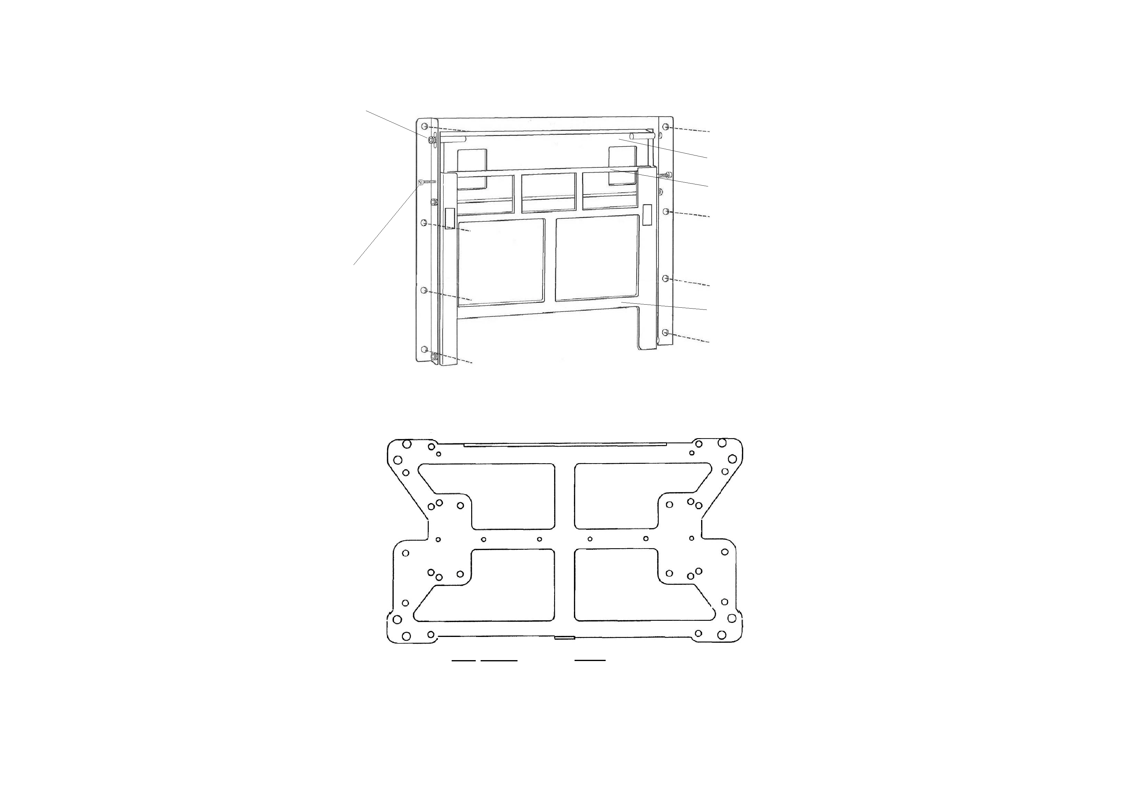
FIG 1
WALL PLATE
Angle adjustment
Socket Screw
M5 Cheese-
head Screws
Tilt Plate
Suspension Bar
(Orange Sticker)
Wall Plate
Strap
FIG 2A
B
A
B
B
B
A
A
A
Hole Screen
A
Hitachi 37/42
B
Hitachi 50
Fixing
4 off, M6 x 20mm + washers
4 off, M8 x 20mm + washers
Nylon Insulating
Washer x4
Security
Bolt
Suspension Hooks
Steel
Washer x4
3 cm
movement
side to side
Angle
adjustment
screw
FIG 4
FIG 5
Fastening
bolt
Suspension Plate
Nylon Insulating Spacer Plug x4
(Panasonic & Toshiba screens)
FIG 3
Hook onto
bar on
wallplate
3 cm
Angle
adjustment
screw
11~20 cm
Wall
Access cable by
pulling display
away from wall at
base of screen
A
A
Fine adjust angle
using Angle
adjustment screw.
Secure screen
using fastening
bolt on backplate
FIG 2