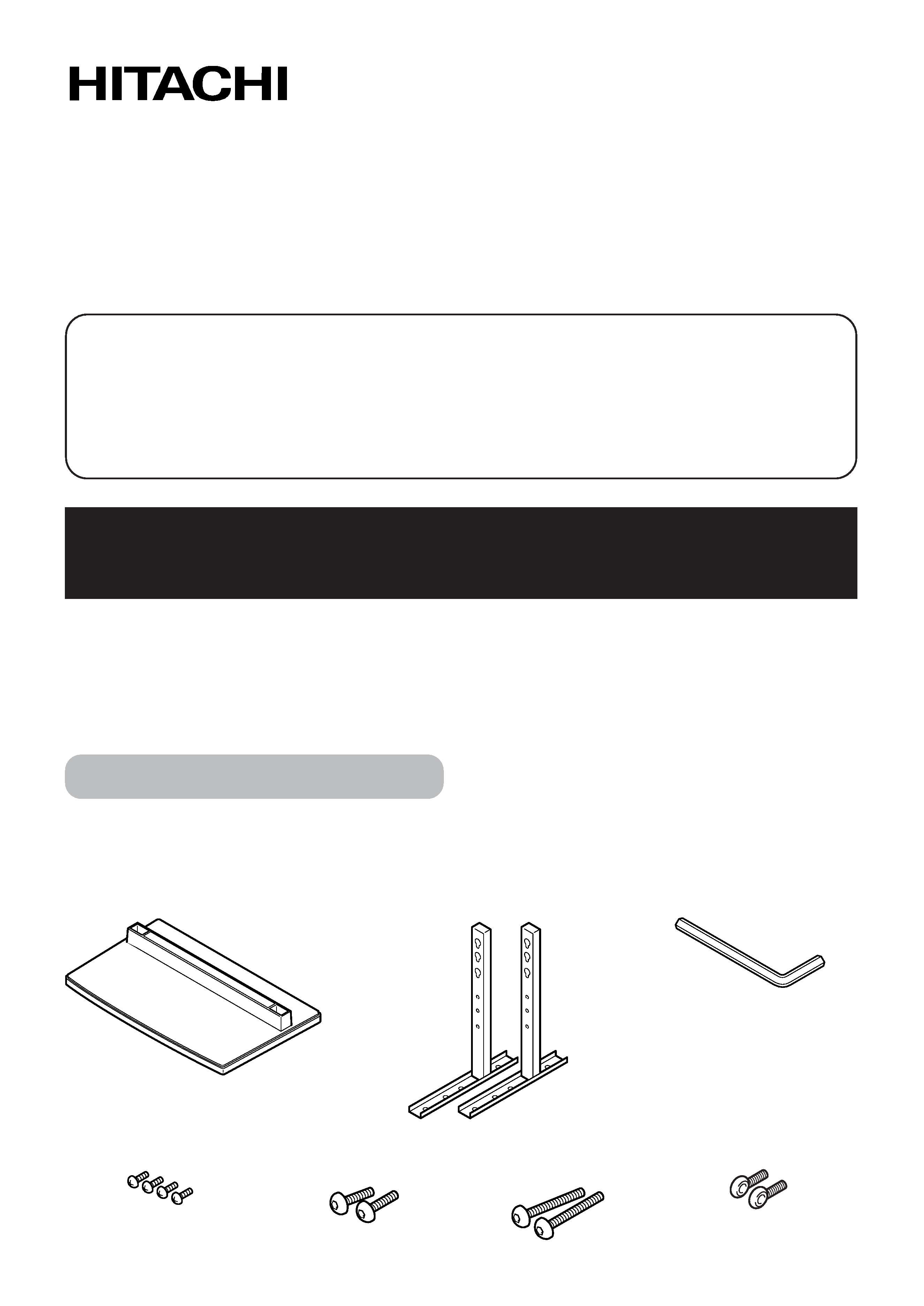
Parts Configuration Chart
IConfirming the parts provided
Before assembly, check to make sure that none of the parts provided are missing.
Hitachi Plasma Display Tabletop Stand
Model
CMPAD06
Installation Instructions
Thank you for purchasing the Hitachi Plasma Display Table top Stand.
To ensure correct usage, please read this instruction manual thoroughly. After reading, please store this
manual in a safe place for future reference.
This plasma display tabletop stand is for use only with the following model:
CMP5000WX
Request an installation specialist to install this unit.
This company assumes absolutely no responsibility for injuries and damages that may occur due to improper
installation and handling.
· Stand pipes
(left and right, interchangable) x 2
· Base cover x 1
· Hexagonal wrench x 1
· Screws (4 x 8) x 4
· Installation bolts 1
(M8 x 20) x 2
· Installation bolts 2
(M8 x 40) x 2
· Stabilization bolts x 2
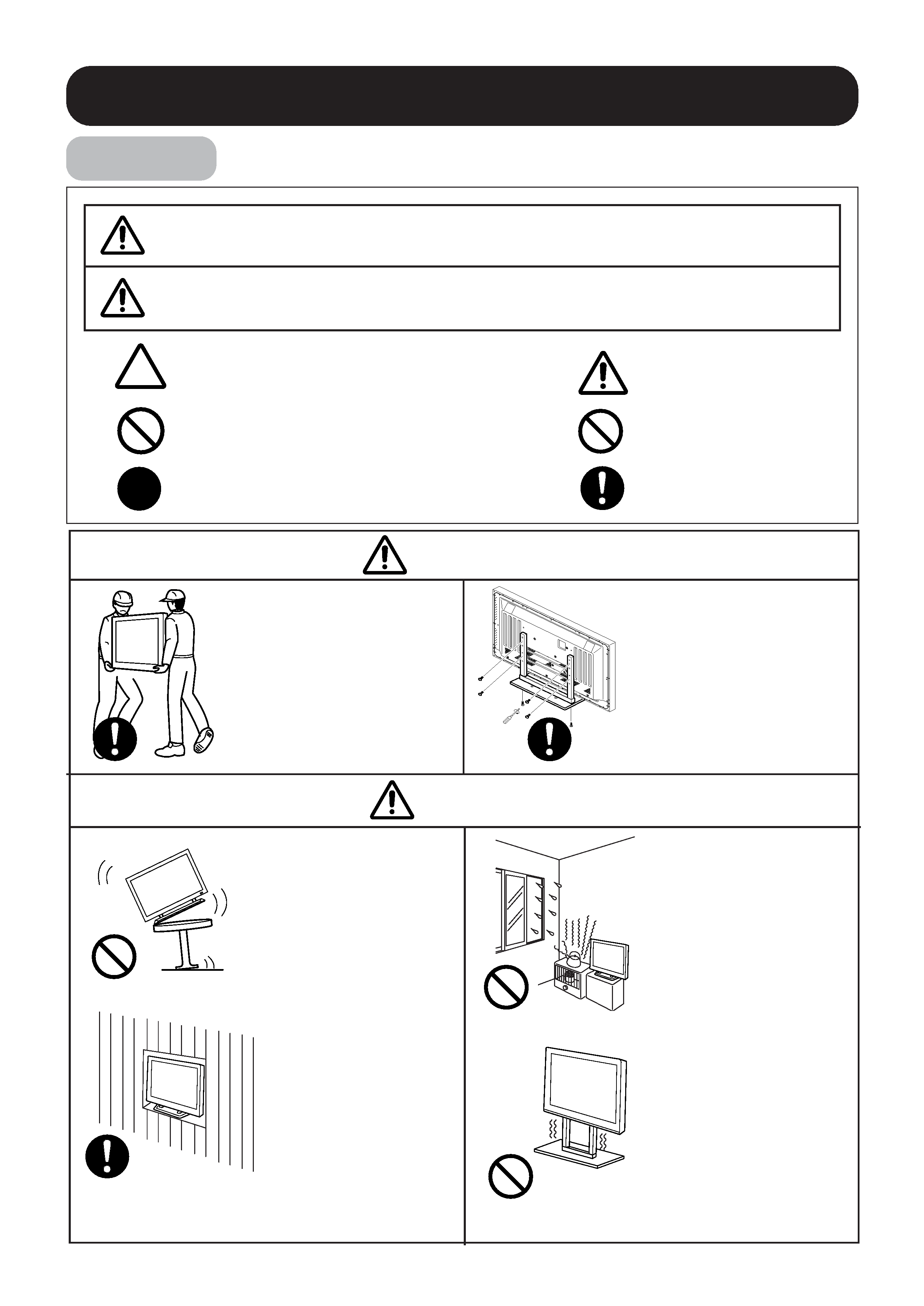
Usage cautions to ensure correct usage
Symbols
The following symbols are used to ensure safe usage of the product, to prevent danger
to yourself and other parties and to prevent damage to property.
This symbol indicates that incorrect handling due to ignoring this symbol
can result in the possibility of personal injury or even death.
This symbol indicates additional
cautions (including warnings).
WARNING
Caution
(general)
This symbol indicates forbidden
actions.
This symbol indicates required actions.
This symbol indicates that incorrect handling due to ignoring this symbol
can result in the possibility of personal injury and physical damage.
CAUTION
Forbidden
(general)
Required
(general)
CAUTION
WARNING
Always use at least
two people to perform
the installation work.
Injury could result from
dropping heavy objects.
Use the specified
bolts and screws in
the specified places
and tighten firmly.
Failure to do this could
cause injury if the plasma
display falls.
Avoid installing in
locations where the
temperature and
humidity are
excessively high, and
where contact with
water is possible.
These can result in fire or
electrical shock.
Do not block the
ventilation holes.
Also provide
sufficient clearance
in regard to avoid
blocking the
ventilation.
The internal temperature
could elevate and
possibly result in fire.
Do not alter any of
the parts. And do
not use broken
parts.
This could result in injury
due to the plasma display
falling.
Do not mount the
plasma display in
an instable place.
The display could fall or
break, resulting in
physical injury.
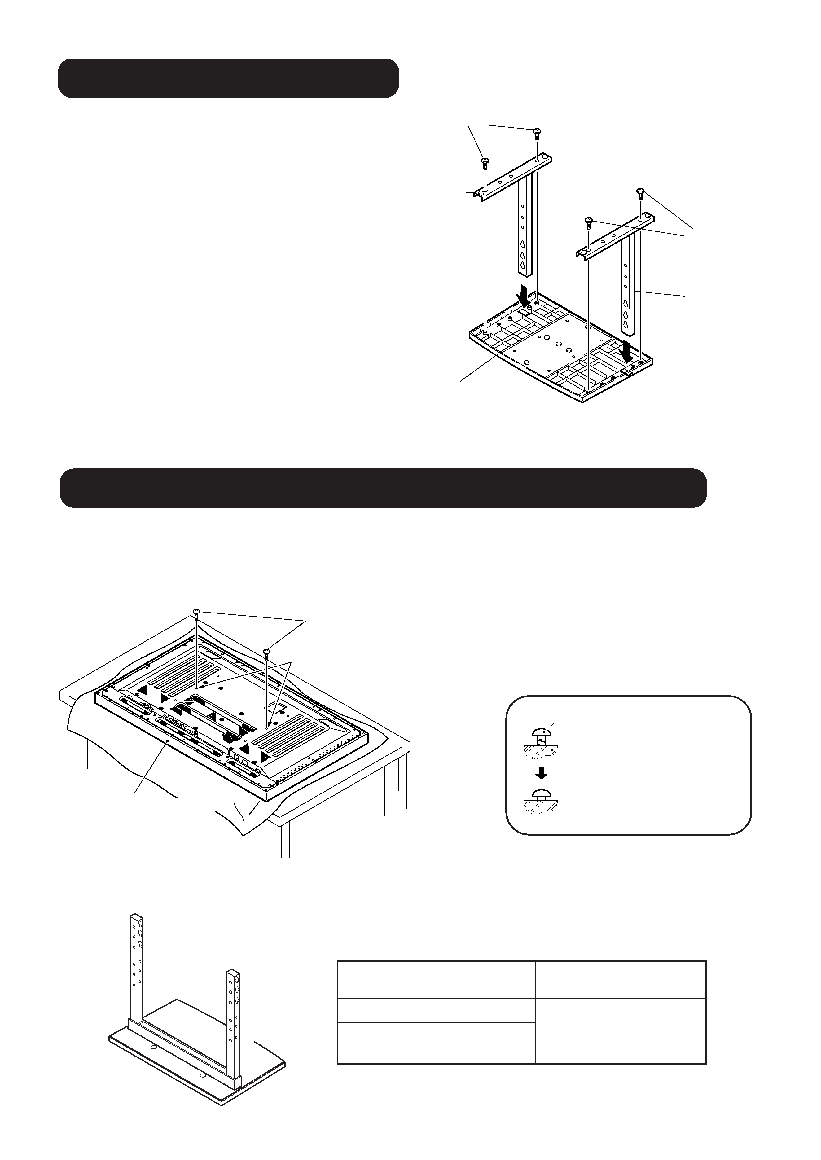
Stand assembling
1. Turn the base cover over so the underside
is facing up.
2. Insert the stand pipes into the base cover.
3. Use the included screws to stabilize the
stand pipes.
Screws (4 x 8)
Stand pipe
Base cover
Screws (4 x 8)
Stand pipe
Stand attaching to the Plasma Display
Normal Installation
Step 1. With the plasma display lying flat, insert and secure the two Installation bolts 1 (M8 x 20) in the holes "a" located in the
plasma display housing.
At this point, tighten these bolts 1 only until the threads are no longer visible when viewed from t he side (you will be
unable to attach the display if the bolts are screwed in completely).
Plasma display
Installation bolt 1 (M8 x 20)
Holes "a"
(holes in center of plasma display)
Installation bolt 1
Plasma display housing
Stop screwing down the bolt
when the threads are no
longer visible.
Regarding the stand pipe screw holes when the stand is used as a desktop stand
C
B
A
C´
B´
A´
B
A
C´
B´
A´
C
Specifications
Screw holes used with
stand orientation
Normal use
B, B'
With optional speakers attached to
both sides of display
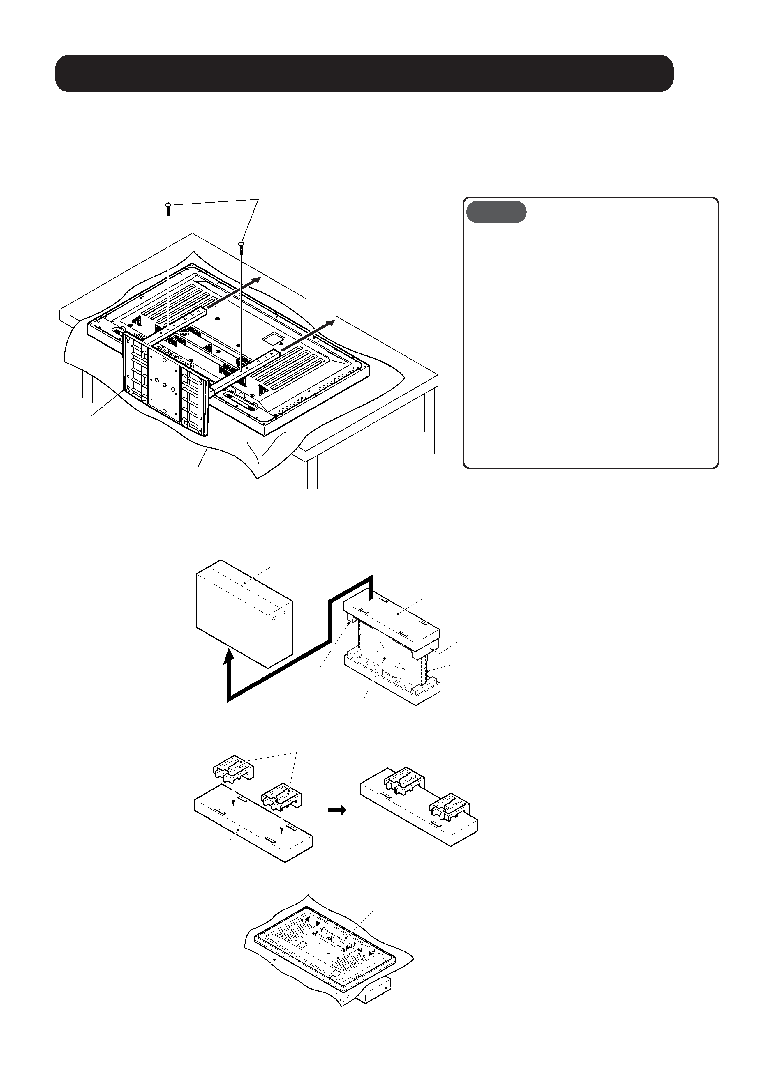
Step 2. As shown in figure, hook the stand pipe holes onto the screw heads of the installation bolts 1, then slide the stand
upwards to the main plasma display until it engages the installation bolts 1 (once put together with the display, the stand
will slides no more than 19 mm (3/4 inch)).
Step 3. Pass the installation bolts 2 (M8 x 40) through the stand pipes and tighten the installation bolts securely with the included
hexagonal wrench.
Step 4. Tighten the installation bolts 1 securely with the hexagonal wrench provided.
· Place a sheet or protective cover to protect the
display from scratches or damage.
· Assemble only with the plasma display lying flat
on a table or similar surface.
· Insert the bolts vertically in the holes and tighten
them, but do not apply excessive pressure that
tightens them more than necessary.
· Move the stand so that the stand screw holes
and the nuts that connect the main display line
up correctly.
· The display is a 50" model that weighs
approximately 40 kilograms (88 lb) and has little
depth, making the display very unstable. For this
reason, at least two people are required for
setup and installation.
Notes
Stand attaching to the Plasma Display
Installation bolts 2 (M8 x 40)
(Step 3)
Table top stand
Slide the stand (Step 2)
Sheet
Instructions for using the main display packing material as a stand for the working on
the display
Main plasma display packaging setup
Step 1. Construct the stand for the plasma display using the inner box frame and pads shown in the figure above (all pads are
identical).
Step 2. Set the plasma display down on the pads as shown in the figure below.
Step 3. Follow the instructions in Steps 1-4 in "Normal Installation" to attach the stand to the plasma display.
Outer box
Inner box frame
Pad
Mirror mat
Pad
Plasma display
Pad
Inner box frame
Plasma display
Inner box frame topped by two pads
Mirror mat
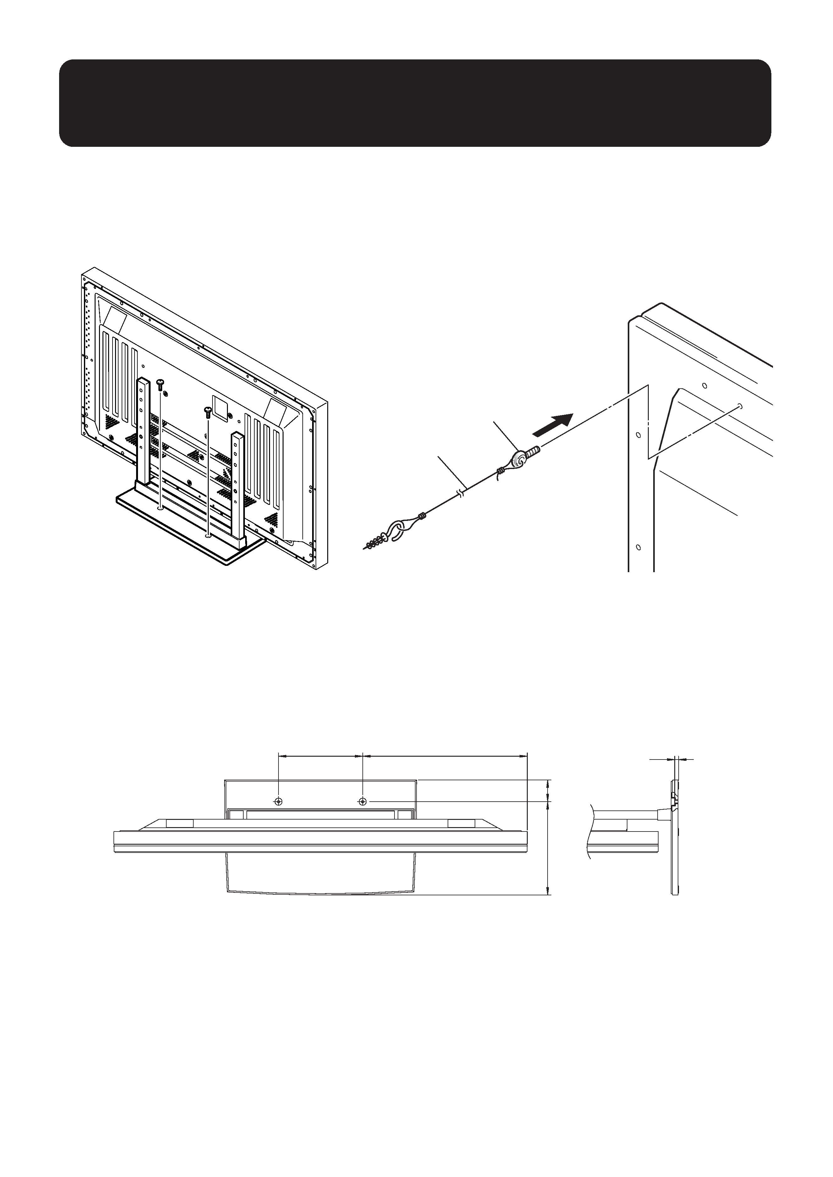
After assembling, connect the stand to the
floor to prevent from falling over.
Stabilizing to the floor
· Use screws (sold separately) to attach and stabilize the
stand.
Sample use of the stabilization bolts
1. Attach the stabilization bolts that come with the plasma
display.
2. Stabilize the display by connecting to a wall or standing
beam with a strong cord.
(Repeat the same steps in the laterally direction to stabilize
the assembly to the left and right.)
Use cord and hooks that are available on the market (sold
separately).
Installation coordinates for screws used to stabilize the stand to the floor
11.5(7/16)
64(2+17/32)
275(10-13/16)
485(19-3/32)
248(9-3/4)