CAUTION:
Before servicing this chassis, it is important that the service technician read the "Safety
Precautions" and "Product Safety Notices" in this service manual.
ATTENTION:
Avant d'effectuer l'entretien du châassis, le technicien doit lire les «Précautions de sécurité»
et les «Notices de sécurité du produit» présentés dans le présent manuel.
VORSICHT:
Vor Öffnen des Gehäuses hat der Service-Ingenieur die ,,Sicherheitshinweise" und ,,Hinweise
zur Produktsicherheit" in diesem Wartungshandbuch zu lesen.
SERVICE MANUAL
MANUEL D'ENTRETIEN
WARTUNGSHANDBUCH
Data
contained
within
this
Service
manual is subject to alteration for
improvement.
Les données fournies dans le présent
manuel d'entretien peuvent faire l'objet
de modifications en vue de perfectionner
le produit.
Die
in
diesem
Wartungshandbuch
enthaltenen Spezifikationen können sich
zwecks Verbesserungen ändern.
SPECIFICATIONS AND PARTS ARE SUBJECT TO CHANGE FOR IMPROVEMENT
LCD Colour Monitor
December 2001
No. 0418
CML170SXWBPlus

1. ELECTRICAL REQUIREMENTS ...............................................1
A. LCD Panel Specification................................................................................. 1
B. Controls.......................................................................................................... 2
C. Power Management ....................................................................................... 2
D. Display Modes for Inspections........................................................................ 3
E. Dot Defects & Audio Specification .................................................................. 4
2. MAIN / DISPLAY CONTROL BOARD - VL-705 .........................5
A. Description ..................................................................................................... 5
B. Features ......................................................................................................... 5
C. Block Diagram (Control Circuit) ...................................................................... 5
D. Connector Locations ...................................................................................... 6
E. Connector Type.............................................................................................. 6
F. Connector Pin Assignment ............................................................................. 6
3. CONTROL PANEL AND AUDIO CONTROL
(KEY BOARD) - VK-517 ......8
A. Description ..................................................................................................... 8
B. Connector and Switch Locations .................................................................... 8
C. Connector Type ............................................................................................. 9
D. Connector Pin Assignment............................................................................. 9
4. POWER AND AUDIO BOARD - VM-517 ....................................11
A. Major Specification ......................................................................................... 11
B. Description ..................................................................................................... 11
C. Electrical Characteristics ................................................................................ 11
D. Connector Location ........................................................................................ 11
E. Connector Type.............................................................................................. 12
F. Connector Pin Assignment ............................................................................. 12
5. INVERTER BOARD - AMBIT T51I036.00 ..................................13
A. Description ..................................................................................................... 13
B. Electrical Characteristics ................................................................................ 13
C. Connector Locations ...................................................................................... 16
D. Connector Pin Assignment............................................................................. 16
6. AC ADAPTER (LSE9901B1260) ................................................17
A. Specification Review ..................................................................................... 17

7. CIRCUIT DESCRIPTION ............................................................17
A. Display Controller ........................................................................................... 17
B. Plug and Play Circuit ...................................................................................... 17
C. System Clock ................................................................................................. 17
D. Power Regulator ............................................................................................ 17
8. INTRODUCTION.........................................................................18
A. Front Panel Controls and LED........................................................................ 18
B. Rear Panel Connectors .................................................................................. 19
9. TROUBLESHOOTING ................................................................20
A. Main Procedure .............................................................................................. 20
B. Power Troubleshooting .................................................................................. 21
C. Backlight Troubleshooting .............................................................................. 22
D. Performance Troubleshooting ........................................................................ 23
E. Function Troubleshooting ............................................................................... 24
APPENDIX A: REPLACEMENT PARTS LISTS ............................25
1
1. ELECTRICAL REQUIREMENTS
A. LCD Panel Specification
Display:
17 inch (17" viewable image size): active matrix: thin film transistor
(TFT): liquid crystal display (LCD): 0.264 mm dot pitch: RGB
Vertical stripe 200 cd/m2 white luminance, typical: 200:1 contrast
ratio, Min.
Compatibility:
640 x 350: VGA-350
720 x 400: VGA text
640 x 400: VGA-GRAPH
640 x 480: VGA, 60Hz to 75 Hz vertical refresh rate
800 x 600: 56Hz to 75 Hz vertical refresh rate
1,024 x 768 non-interlaced: 60Hz to 75 Hz vertical refresh rate
1,280 x 1,024 non-interlaced: 60~75Hz vertical refresh rate
Synchronisation
Frequencies:
Horizontal:
24~80KHz
Vertical:
56~75Hz
Pixel Frequency: 25~135 MHz
Resolution:
Horizontal:
1,280 dots
Vertical:
1,024 lines
Active Display Area:
Horizontal:
337.92 mm
Vertical:
270.34 mm
Viewing Angles:
Up 40º, Down 80º (typical)
Left 60º, Right 80º (typical)
CR 10
Display Colours:
16,777,216 (with FRC)
Power Supply:
AC 100 to 240V worldwide input, 50/60Hz
Power
Consumption:
Typical: 50W on mode +10 / -25%
Environmental:
Operating temperature: 0~50ºC
Storage temperature: -20~65ºC
Relative Humidity: 20~80%
2
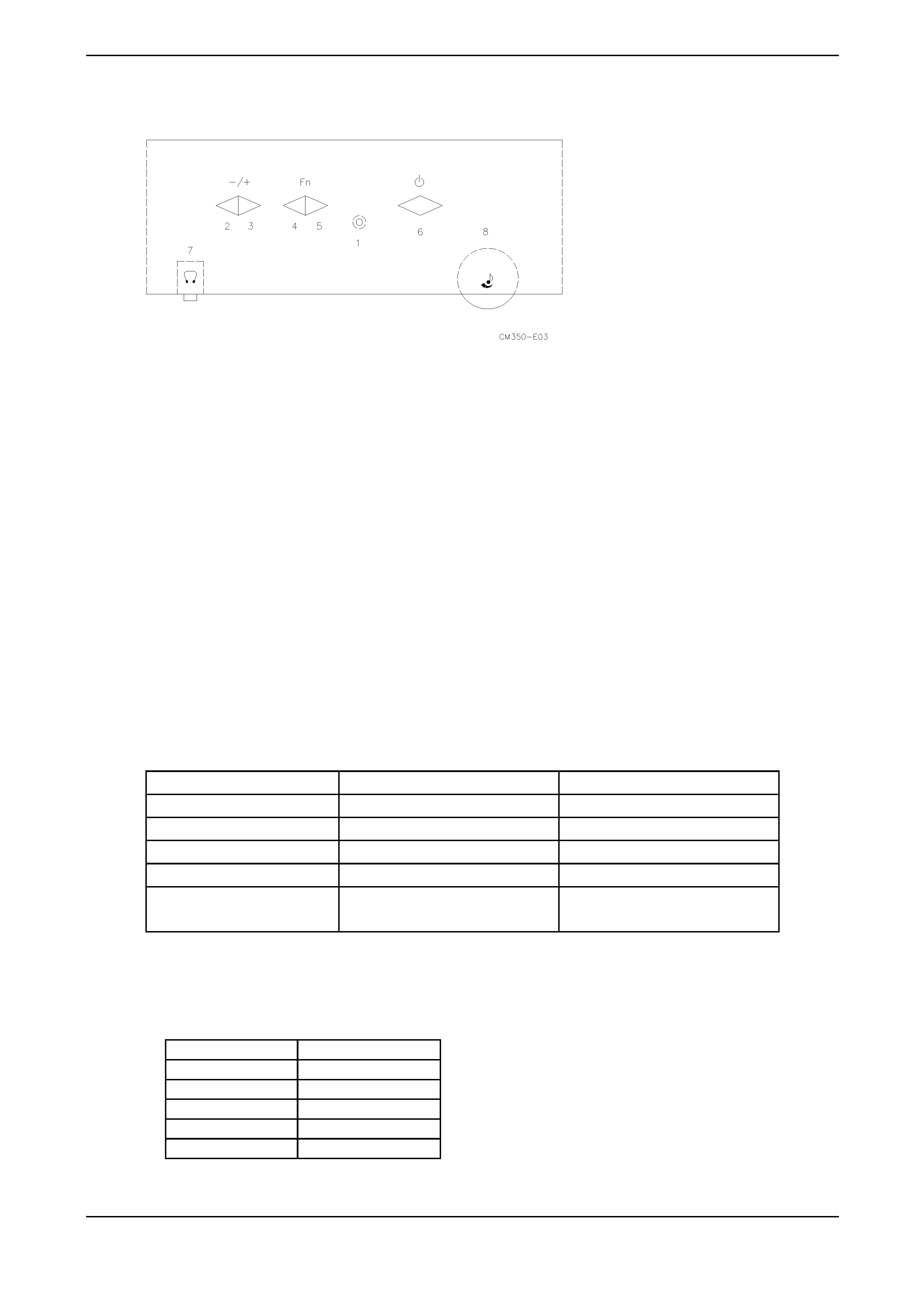
B. CONTROLS
B-1 Control Panel (Monitor Front Panel)
1. Power LED.
2. Adjust decrease.
3. Adjust increase.
4. Function select anti-clockwise.
5. Function select clockwise.
6. Power ON/OFF switch, push to ON and push to OFF. (Toggle switch)
7. Ear-phone jack.
8. Volume Control.
C. Power Management
C-1 Power Management
1. Meets VESA DPMS Proposal
2. Power Consumption
Meets VESA DPMS Proposal
On-mode
54 Wmax
Green
Stand-by
5 Wmax
Yellow
Suspend
5 Wmax
Yellow
Off-mode
5 Wmax
Yellow
DC power off
5 Wmax
Dark
Disconnection
5 Wmax
Dark (DC power off)
Yellow (DC power on)
Power saving states are measured with speakers attached but not working.
The recovery time from stand-by/suspend/off-mode to on-mode is 3 seconds maximum.
C-2 Power Consumption
Meets VESA DPMS Proposal
On-mode
54 Wmax
Stand-by
5 Wmax
Suspend
5 Wmax
Off-mode
5 Wmax
DC power off
5 Wmax
Disconnection
5 Wmax
1.
Measured from AC input end of AC power adapter.
2.
Power saving states are measured with speakers attached but not worked.