CAUTION:
Before servicing this chassis, it is important that the service technician read the "Safety
Precautions" and "Product Safety Notices" in this service manual.
ATTENTION:
Avant d'effectuer l'entretien du châassis, le technicien doit lire les «Précautions de sécurité»
et les «Notices de sécurité du produit» présentés dans le présent manuel.
VORSICHT:
Vor Öffnen des Gehäuses hat der Service-Ingenieur die ,,Sicherheitshinweise" und ,,Hinweise
zur Produktsicherheit" in diesem Wartungshandbuch zu lesen.
SERVICE MANUAL
MANUEL D'ENTRETIEN
WARTUNGSHANDBUCH
Data
contained
within
this
Service
manual is subject to alteration for
improvement.
Les données fournies dans le présent
manuel d'entretien peuvent faire l'objet
de modifications en vue de perfectionner
le produit.
Die
in
diesem
Wartungshandbuch
enthaltenen Spezifikationen können sich
zwecks Verbesserungen ändern.
«MODEL NAMES»
SPECIFICATIONS AND PARTS ARE SUBJECT TO CHANGE FOR IMPROVEMENT
LCD Colour Monitor
November 2003
No. 0421
CML156XW
CML158XW

SAFETY PRECAUTIONS
WARNING: The following precautions must be observed.
ALL PRODUCTS
Before any service is performed on the chassis an
isolation transformer should be inserted between the
power line and the product.
1. When replacing the chassis in the cabinet, ensure
all the protective devices are put back in place.
2. When service is required, observe the original
lead dressing. Extra precaution should be taken to
ensure correct lead dressing in any high voltage
circuitry area.
3. Many electrical
and
mechanical parts in
HITACHI products have special safety related
characteristics. These characteristics are often not
evident from visual inspection, nor can the
protection afforded by them necessarily be
obtained by using replacement components rated
for higher voltage, wattage, etc. Replacement
parts
which
have
these
special
safety
characteristics are identified by marking with a
! on the schematics and the replacement parts
list.
The use of a substitute replacement component
that does not have the same safety characteristics
as the HITACHI recommended replacement one,
shown in the parts list, may create electrical
shock, fire, X-radiation, or other hazards.
4. Always replace original spacers and maintain lead
lengths. Furthermore, where a short circuit has
occurred, replace those components that indicate
evidence of overheating.
5. Insulation resistance should not be less than 2M
ohms at 500V DC between the main poles and
any accessible metal parts.
6. No flashover or breakdown should occur during
the dielectric strength test, applying 3kV AC or
4.25kV DC for two seconds between the main
poles and accessible metal parts.
7. Before returning a serviced product to the
customer, the service technician must thoroughly
test the unit to be certain that it is completely safe
to operate without danger of electrical shock. The
service technician must make sure that no
protective device built into the instrument by the
manufacturer
has
become
defective,
or
inadvertently damaged during servicing.
CE MARK
1. HITACHI products may contain the CE mark on
the rating plate indicating that the product
contains parts that have been specifically
approved
to
provide
electromagnetic
compatibility to designated levels.
2. When replacing any part in this product, please
use only the correct part itemised in the parts list
to ensure this standard is maintained, and take
care to replace lead dressing to its original state,
as this can have a bearing on the electromagnetic
radiation/immunity.
PICTURE TUBE
1. The line output stage can develop voltages in
excess of 25kV; if the E.H.T. cap is required to be
removed, discharge the anode to chassis via a
high value resistor, prior to its removal from the
picture tube.
2. High voltage should always be kept at the rated
value of the chassis and no higher. Operating at
higher voltages may cause a failure of the picture
tube or high voltage supply, and also, under
certain circumstances could produce X-radiation
levels moderately in excess of design levels. The
high voltage must not, under any circumstances,
exceed 29kV on the chassis (except for projection
Televisions).
3. The primary source of X-radiation in the product
is the picture tube. The picture tube utilised for
the above mentioned function in this chassis is
specially constructed to limit X-radiation. For
continued X-radiation protection, replace tube
with the same type as the original HITACHI
approved type
4. Keep the picture tube away from the body while
handling. Do not install, remove, or handle the
picture tube in any manner unless shatterproof
goggles are worn. People not so equipped should
be kept away while picture tubes are handled
LASERS
If the product contains a laser avoid direct exposure to
the beam when the cover is open or when interlocks are
defeated or have failed.

1
1. ELECTRICAL REQUIREMENTS
1.1
LCD Panel Specification ...................................................................................................................... 2
1.2
Input Signals ........................................................................................................................................ 7
1.3
Supported Timing ................................................................................................................................ 8
1.4
Power Management............................................................................................................................. 9
1.5
Plug & Play .......................................................................................................................................... 9
1.6
External Connection ............................................................................................................................ 9
2. ADJUSTMENT OF POWER SUPPLY
3. VL-563 DISPLAY CONTROL BOARD
3.1
Description......................................................................................................................................... 11
3.2
Features............................................................................................................................................. 11
3.3
BLOCK DIAGRAM............................................................................................................................. 12
3.4
Connector Locations.......................................................................................................................... 12
3.5
Connector Type ................................................................................................................................. 13
3.6
Connector pin assignment................................................................................................................. 13
4. VK-580 CONTROL PANEL AND AUDIO BOARD
(CML158XW)
4.1
Description......................................................................................................................................... 16
4.2
Electrical characteristics (Tamb=25
°)................................................................................................ 16
4.3
Connector type .................................................................................................................................. 16
4.4
Connector pin Assignment ................................................................................................................ 17
4.5
Switch definition................................................................................................................................. 18
4.6
LED definition .................................................................................................................................... 18
4.7
Variable resistor................................................................................................................................. 18
5. VK-570 CONTROL PANEL (CML156XW)
5.1
Description......................................................................................................................................... 19
5.2
Connector pin Assignment ................................................................................................................ 19
5.3
Switch definition................................................................................................................................. 19
5.4
LED definition .................................................................................................................................... 19
6. VP-570 POWER BOARD
6.1
Description......................................................................................................................................... 20
6.2
Features............................................................................................................................................. 20
6.3
Interface Signals ................................................................................................................................ 20
6.4
Electrical Specification:...................................................................................................................... 21
6.5
Isolation Check
.................................................................................................................................. 23
6.6
Environmental.................................................................................................................................... 24
7. INTRODUCTION
7.1
Front Panel Control and Led.............................................................................................................. 25
7.2
Rear Panel connector Input Signals .................................................................................................. 27
8. TROUBLESHOOTING
8.1
Main Procedure ................................................................................................................................. 28
APPENDIX A: DISPLAY UNIT ASSEMBLY......................................................................33

2
1. ELECTRICAL REQUIREMENTS
1.1 LCD Panel Specification
1.1.1 LCD Panel Model
(HSD150SX84-C)
· Display Type
Active matrix colour TFT LCD
· Resolution
1024 x 768 pixels
· Display Dot
1024 x (RGB) x 768
· Display Area
304.1mm (H) x 228.1mm (V)
· Pixel Pitch
0.297mm (H) x 0.297mm (V)
· Display Colour
262,144
(Monitor display colour 16.7M
with FRC or dithering)
· Maximum Brightness
250 cd/m2 typ.
(6mA for each lamp after 30 min.)
· Contrast Ratio
400:1 typ.
· Response Time (Tr+Tf)
35ms typ
· Lamp Voltage
660Vrms typ.
· Lamp Current
3~7mA rms. typ. x 2 (Lamp)
· View Angle (Hor./Ver.)
65
°(L), 65°(R) / 45°(H), 55°(L). typ.
(Contrast Ratio
10)
· Uniformity =(Bmin/Bmax)x100%
70% min.
Bmax: Maximum Brightness
Bmin: Minimum Brightness
· Weight
950g. typ.
3
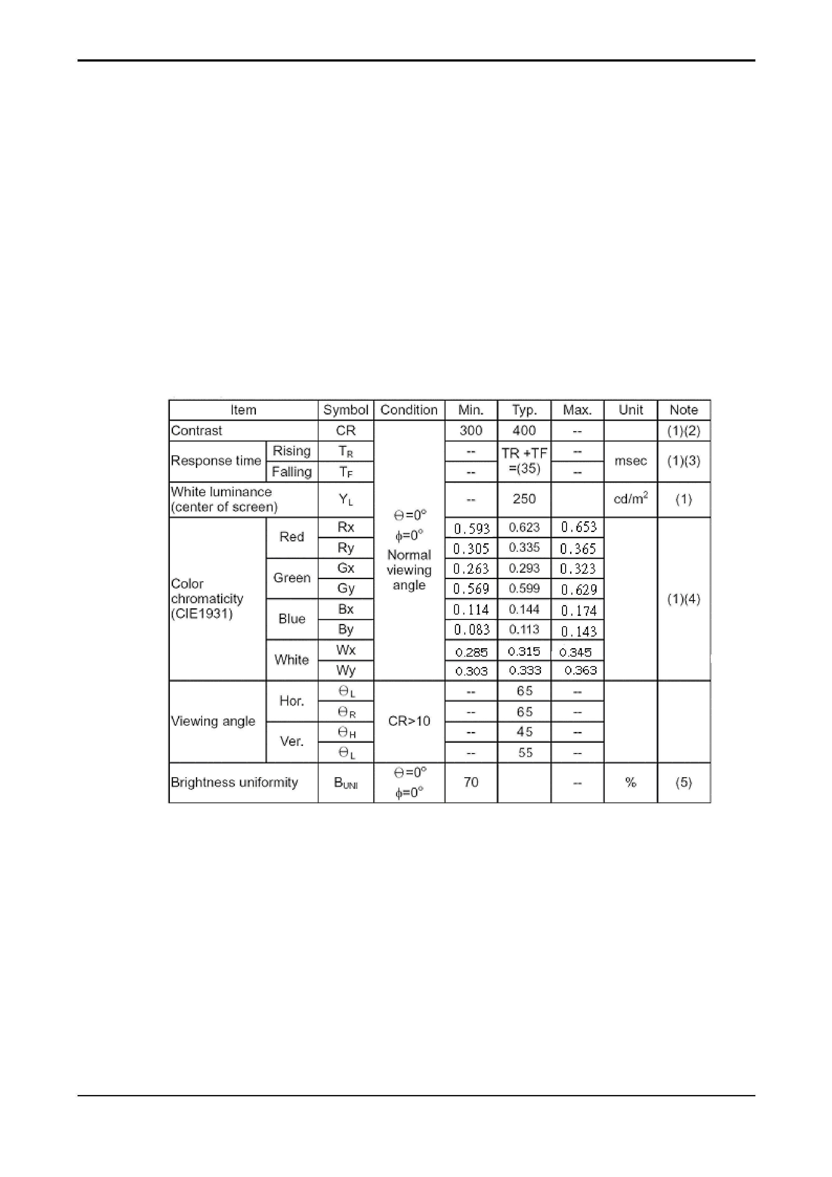
1.1.2 Optical Characteristics
Measuring Condition
Measuring surrounding
s : dark room
Lamp current IBL : (6.0) ±0.1mA,
Lamp freq. FL =50KHz
VDD1 =3.3V, fv =60Hz, fDCLK =32.5
MHz
Surrounding temperature : 25 ±2°C
30min. Warm-up time.
Measuring Equipment
LCD-7000 (Otsuka Electric Corp.) utilises MCPD-7000 for Chromaticity and BM-5A for
other optical characteristics.
Measuring spot size : 10~12mm
Optical
Specification
JS555-E26