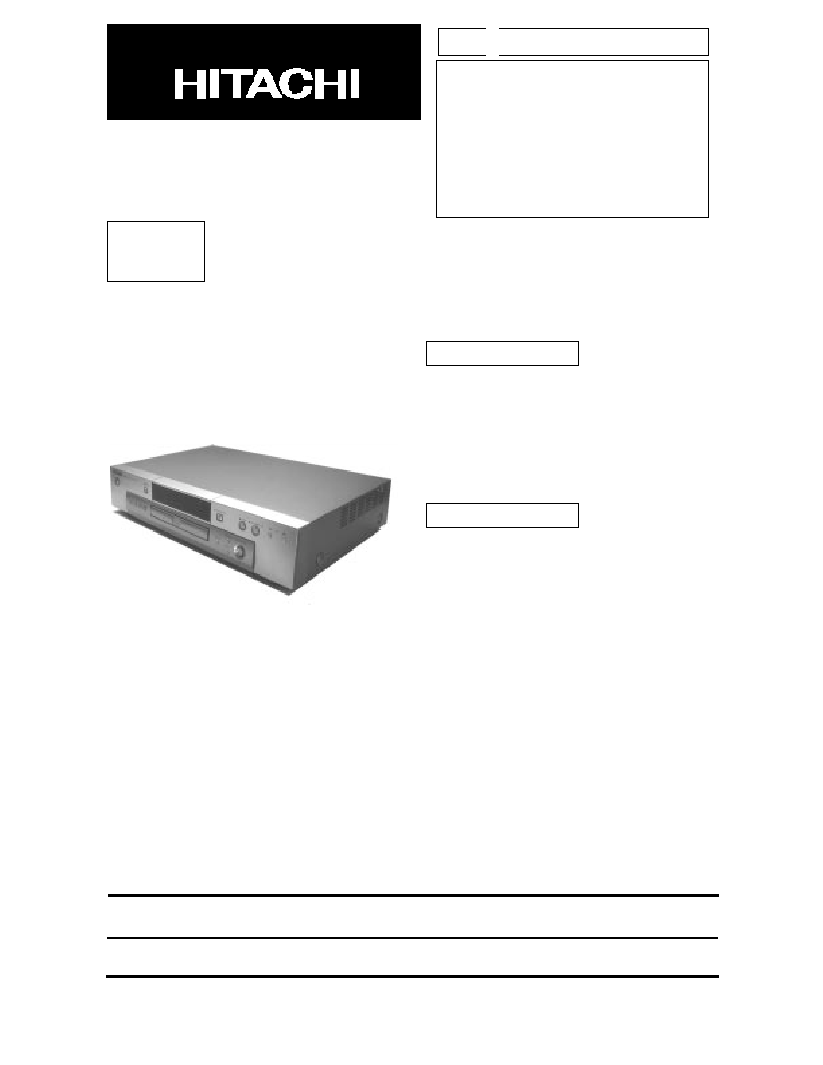
This is a device for DVD playback.
This device is to be used by connecting it to the
video input terminal of a TV set.
6
Disc navigation system facilitates program
search.
6
Speedy operation by 2x speed drive.
ADVICE
Please carefully read this guide before using the device. The Hitachi DVD Player has been designed to
prevent fire, electrical shock, injury, or harmful radiation. It has been legally fabricated in accordance with
the Electrical Appliances Act. Therefore, when using the device, please follow advice in this service
guide to keep it safe to use.
1. In brief
2. Features
SPECIFICATIONS AND PARTS ARE SUBJECT TO CHANGE FOR IMPROVEMENT.
May 2000
Digital Media Products Division, Tokai
SERVICE MANUAL
DV-P505U
DV-P505E
DV-P505E(UK)
DV-P505U(PX)
TK
NO. 9002E
DVD PLAYER

I
Before undertaking repair work, please read through this [Precautions for safety].
The following points should be observed in order to prevent accidents from happening and to ensure the
safety of the device.
!
Degrees of danger or damage that can be caused by faulty operation are indicated by the following marks:
!
The following marks identify actions to be taken:
PRECAUTIONS FOR SAFETY(Please follow.)
Under this mark, there is "Possible death or serious injury".
Under this mark, there is "Possible injury or material damage".
This mark indicates items to which `You
should pay attention'.
This mark indicates items `You have to
accomplish'.
This mark indicates: `You should be cau-
tious of electric shock'.
This mark indicates `Forbidden items'.
!
You should pay attention.
!
The original part installation and wiring route
shall be restored.
Where a special attention is required, it is
indicated by a label or stamp. For example, on
the cabinet, chassis, or parts.
Please respect the indicated items and the
`Precautions for use' of the manual.
For safety, some parts are insulated by a tube
or a tape, or installed without contact with
substrate. The internal wiring is kept a
distance from hot or high voltage parts by
clamps or routing. Please restore them as
initially done to prevent electric shock or fire
from happening.
!
You should be cautious against electric shock.
Please be careful during operations because
there are high voltage and recharging parts
inside. An electric shock or death may happen
by touching them.
When disassembling, assembling, or replacing
a part, the power plug has to be pulled off.
Touching by error a powered part may cause
an electric shock, death, or injury.
!
Please check safety after servicing.
Please check if dismounted screws, parts, and
wires are reinstalled as before and if the area
surrounding the repair is damaged.
Please also measure insulation resistance with
a ohmmeter and to confirm that it is more than
20M
.
There is risk of electric shock or fire if the
insulation resistance is less than 20M
.
!
Please use designated parts.
Parts are characterized by uninflammability
and voltage resistance. Therefore, parts
having these same characteristics must be
used in replacement.
Especially for parts important in insuring
safety, identified by
in the schematic or
parts list, a part with the identical part number
shall be used.
If a part with a different part number is used,
an electric shock or a fire may occur.
WARNING
CAUTION
WARNING


II
Chapter 1
System Introduction
1
System Specification . . . . . . . . . . . . . . . . . . . . . . . . . . . . . . . . . . . . . . . . . . . . . . . . . . .1
Hitachi DV-P505U/U(PX) . . . . . . . . . . . . . . . . . . . . . . . . . . . . . . . . . . . . . . . . . . .1
Hitachi DV-P505E/(UK) . . . . . . . . . . . . . . . . . . . . . . . . . . . . . . . . . . . . . . . . . . . . .2
System Outlook . . . . . . . . . . . . . . . . . . . . . . . . . . . . . . . . . . . . . . . . . . . . . . . . . . . . . . .3
Front Panel . . . . . . . . . . . . . . . . . . . . . . . . . . . . . . . . . . . . . . . . . . . . . . . . . . . . . .3
Display Window . . . . . . . . . . . . . . . . . . . . . . . . . . . . . . . . . . . . . . . . . . . . . . . . . . .3
Rear Panel . . . . . . . . . . . . . . . . . . . . . . . . . . . . . . . . . . . . . . . . . . . . . . . . . . . . . . .4
Description of adopted new technology . . . . . . . . . . . . . . . . . . . . . . . . . . . . . . . . . . . . .5
Digital signal circuit . . . . . . . . . . . . . . . . . . . . . . . . . . . . . . . . . . . . . . . . . . . . . . . .5
Video circuit (DEC substrate). . . . . . . . . . . . . . . . . . . . . . . . . . . . . . . . . . . . . . . . .6
Video Output Circuit (VDO substrate) . . . . . . . . . . . . . . . . . . . . . . . . . . . . . . . . . .9
Audio Circuit. . . . . . . . . . . . . . . . . . . . . . . . . . . . . . . . . . . . . . . . . . . . . . . . . . . . .11
FRONT (FSW) SUBSTRATE CIRCUIT . . . . . . . . . . . . . . . . . . . . . . . . . . . . . . . .12
POWER SUPPLY CIRCUIT. . . . . . . . . . . . . . . . . . . . . . . . . . . . . . . . . . . . . . . . .12
CLOCK CIRCUITS. . . . . . . . . . . . . . . . . . . . . . . . . . . . . . . . . . . . . . . . . . . . . . . .13
Troubleshooting . . . . . . . . . . . . . . . . . . . . . . . . . . . . . . . . . . . . . . . . . . . . . . . . . . . . . .16
VIDEO CIRCUIT . . . . . . . . . . . . . . . . . . . . . . . . . . . . . . . . . . . . . . . . . . . . . . . . .16
AUDIO CIRCUIT . . . . . . . . . . . . . . . . . . . . . . . . . . . . . . . . . . . . . . . . . . . . . . . . .17
About System Reset Function . . . . . . . . . . . . . . . . . . . . . . . . . . . . . . . . . . . . . . .20
System Utility . . . . . . . . . . . . . . . . . . . . . . . . . . . . . . . . . . . . . . . . . . . . . . . . . . . .20
Chapter 2
Removal and Replacement
21
General Information . . . . . . . . . . . . . . . . . . . . . . . . . . . . . . . . . . . . . . . . . . . . . . . . . . .22
Before You Begin . . . . . . . . . . . . . . . . . . . . . . . . . . . . . . . . . . . . . . . . . . . . . . . . .22
Disassembly Procedure Flowchart . . . . . . . . . . . . . . . . . . . . . . . . . . . . . . . . . . . . . . .23
Disassembly Procedure . . . . . . . . . . . . . . . . . . . . . . . . . . . . . . . . . . . . . . . . . . . . . . . .24
Removing the Top Cover . . . . . . . . . . . . . . . . . . . . . . . . . . . . . . . . . . . . . . . . . . .24
Removing the Foot Stand . . . . . . . . . . . . . . . . . . . . . . . . . . . . . . . . . . . . . . . . . .24
Removing the Front Panel . . . . . . . . . . . . . . . . . . . . . . . . . . . . . . . . . . . . . . . . . .25
Removing the MPEG Control Board . . . . . . . . . . . . . . . . . . . . . . . . . . . . . . . . . .26
Removing the Power Supply Board . . . . . . . . . . . . . . . . . . . . . . . . . . . . . . . . . . .27
Removing the DVD-ROM Drive . . . . . . . . . . . . . . . . . . . . . . . . . . . . . . . . . . . . . .27
Removing the Outlet Board . . . . . . . . . . . . . . . . . . . . . . . . . . . . . . . . . . . . . . . . .28
Removing the Front Panel Control Boards . . . . . . . . . . . . . . . . . . . . . . . . . . . . .29
Connector Location . . . . . . . . . . . . . . . . . . . . . . . . . . . . . . . . . . . . . . . . . . . . . . .30
Appendix A Schematics
33
Table Of Contents