APRIL 2003
HHEA-MANUFACTURING DIVISION
PA
No. 0174
32HDT50/55:
PT3-E Chassis
42HDT50/55:
PT3-G Chassis
AVC50:
AVC3-U Chassis
R/C: CLU-5726TSI
N
N T
T S
S C
C
P
PT
T3
3--E
E//G
G A
AV
VC
C3
3--U
U
C
Ch
ha
as
ss
siis
s
SERVICE MANUAL
CONTENTS
SAFETY PRECAUTIONS . . . . . . . . . . . . . . . . . . . . . . . . . . . . . . . . . . . . . . . . . . . . . . 2
PRODUCT SAFETY NOTICE . . . . . . . . . . . . . . . . . . . . . . . . . . . . . . . . . . . . . . . . . . . .3
SERVICING PRECAUTIONS . . . . . . . . . . . . . . . . . . . . . . . . . . . . . . . . . . . . . . . . . . . .4
AGENCY REGULATORY INFORMATION . . . . . . . . . . . . . . . . . . . . . . . . . . . . . . . . . . .8
ACKNOWLEDGMENTS AND TRADEMARKS . . . . . . . . . . . . . . . . . . . . . . . . . . . . . . . .9
INTRODUCTION . . . . . . . . . . . . . . . . . . . . . . . . . . . . . . . . . . . . . . . . . . . . . . . . . . . .10
SPECIFICATIONS . . . . . . . . . . . . . . . . . . . . . . . . . . . . . . . . . . . . . . . . . . . . . . . . . . .11
BASIC SETUP & OPERATION . . . . . . . . . . . . . . . . . . . . . . . . . . . . . . . . . . . . . . . . . .14
ADJUSTMENTS . . . . . . . . . . . . . . . . . . . . . . . . . . . . . . . . . . . . . . . . . . . . . . . . . . . . .29
TROUBLESHOOTING FLOWCHARTS . . . . . . . . . . . . . . . . . . . . . . . . . . . . . . . . . . . .48
WAVEFORMS . . . . . . . . . . . . . . . . . . . . . . . . . . . . . . . . . . . . . . . . . . . . . . . . . . . . . .53
DC VOLTAGE TABLES . . . . . . . . . . . . . . . . . . . . . . . . . . . . . . . . . . . . . . . . . . . . . . . .56
CIRCUIT SCHEMATIC DIAGRAMS . . . . . . . . . . . . . . . . . . . . . . . . . . . . . . . . . . . . . .69
PRINTED CIRCUIT BOARDS . . . . . . . . . . . . . . . . . . . . . . . . . . . . . . . . . . . . . . . . . . .84
BLOCK DIAGRAMS . . . . . . . . . . . . . . . . . . . . . . . . . . . . . . . . . . . . . . . . . . . . . . . . . .91
CONNECTION DIAGRAMS . . . . . . . . . . . . . . . . . . . . . . . . . . . . . . . . . . . . . . . . . . . .97
WIRING DIAGRAMS . . . . . . . . . . . . . . . . . . . . . . . . . . . . . . . . . . . . . . . . . . . . . . . . .99
EXPLODED VIEW DIAGRAMS . . . . . . . . . . . . . . . . . . . . . . . . . . . . . . . . . . . . . . . . .104
PARTS LIST . . . . . . . . . . . . . . . . . . . . . . . . . . . . . . . . . . . . . . . . . . . . . . . . . . . . . . .107
QUICK REFERENCE PARTS LIST . . . . . . . . . . . . . . . . . . . . . . . . . . . . . . . . . . . . . .130
DVI CABLE PIN CONFIGURATION . . . . . . . . . . . . . . . . . . . . . . . . . . . . . . . . . . . . .131
CAUTION:
These servicing instructions are for use by qualified service personnel only. To reduce the risk of
electric shock do not perform any servicing other than that contained in the operating instructions
unless you are qualified to do so.
Before servicing this chassis, it is important that the service
technician read the "IMPORTANT SAFETY INSTRUCTIONS" in this service manual.
SAFETY NOTICE
USE ISOLATION TRANSFORMER WHEN SERVICING
Components having special safety characteristics are identified by a
on the schematics and on the parts list in this
Service Data and its supplements and bulletins. Before servicing the chassis, it is important that the service technician
read and follow the "Important Safety Instructions" in this Service Manual.
PLASMA DISPLAY PANEL
SPECIFICATIONS AND PARTS ARE SUBJECT TO CHANGE FOR IMPROVEMENT
!
NOTE: This product is to be serviced at board level.
PWB Part Numbers Added . . . . . . . . . . . . . . . . . . . . . . . . . . . . . . . . . . . . . . . . . . . . . .132
updated 03/25/04
TO GO TO A CHAPTER, CLICK ON ITS HEADING BELOW
updated 7/15/04
Version 0174.03
2
PT3-E/G AVC3-U
NOTICE:
Comply with all cautions and safety-related notes
located on or inside the cover case and on the chassis or plasma
module.
WARNING:
Since the chassis of the AVC unit and Plasma Panel
unit is connected to both sides of the AC power supply during
operation, whenever the receiver is plugged in, service should
not be attempted by anyone unfamiliar with the precautions
necessary when working on this type of receiver.
1. When service is required, an isolation transformer should be
inserted between power line and the receiver before any
service is performed on a "HOT" chassis receiver.
2. When replacing a chassis in the receiver, all the protective
devices must be put back in place, such as barriers, non-
metallic knobs, insulating cover-shields, and isolation
resistors, capacitors, etc.
3. When service is required, observe the original lead dress.
4. Always use manufacturer's replacement components. Critical
components as indicated on the circuit diagram should not be
replaced by another manufacturer's. Furthermore, where a
short circuit has occurred, replace those components that
indicate evidence of over heating.
5. Before returning a serviced receiver to the customer, the
service technician must thoroughly test the unit to be certain
that it is completely safe to operate without danger of electrical
shock, and be sure that no protective device built into the
receiver by the manufacturer has become defective, or
inadvertently defeated during servicing.
Therefore, the following checks should be performed for the
continued protection of the customer and service technician.
Leakage Current Cold Check
With the AC plug removed from the 120V AC 60Hz source,
place a jumper across Line 1 and Line 2 of the three plug
prongs, do not connect with the third prong, which is physical
ground.
Using an insulation tester (DC500V), connect one of its leads
to the AC plug jumper and touch with the other lead each
exposed metal part (antennas, screwheads, metal overlays,
control shafts, etc.), particularly any exposed metal part
having a return path to the chassis should have a resistor
reading over 4M. Any resistance value below this range
indicates an abnormality which requires corrective action. An
exposed metal part not having a return path to the chassis will
indicate an open circuit.
SAFETY PRECAUTIONS
Leakage Current Hot Check
This check must be done considering the AVC or the PDP
monitor as one instrument each.
With any of the instruments completely reassembled (being
the instrument either the AVC center or the PDP monitor), plug
the AC line cord directly into a 120V AC outlet. (Do not use an
isolation transformer during this test.) Use a leakage current
tester or a metering system that complies with the American
National Standards Institute (ANSI) C101.0 Leakage Current
for Appliances. In the case of the PDP monitor set the AC
switch first in the ON position and then in the OFF position,
measure from a known earth ground (metal waterpipe,
conduit, etc.) to all exposed metal parts of the instrument
(antennas, handle bracket, metal cabinet, screw heads,
metallic overlays, control shafts, etc.), especially any exposed
metal parts that offer an electrical return path to the chassis.
Any current measured must not exceed 0.5 milliamps.
Reverse the instrument power cord plug in the outlet and
repeat test.
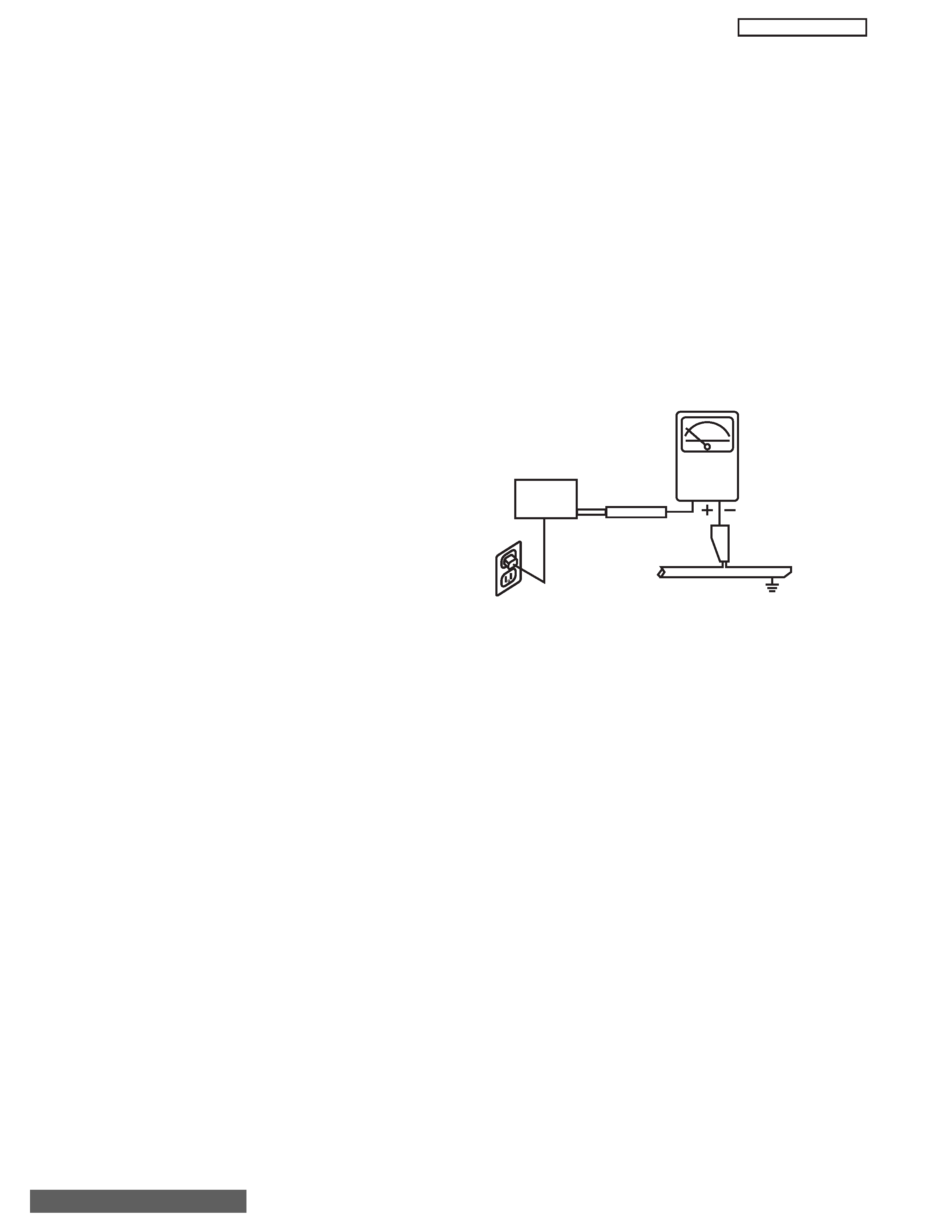
AC LEAKAGE TEST
ANY MEASUREMENTS NOT WITHIN THE LIMITS OUTLINED
ABOVE ARE INDICATIVE OF A POTENTIAL SHOCK HAZARD
AND MUST BE CORRECTED BEFORE RETURNING THE
RECEIVER TO THE CUSTOMER.
LEAKAGE
CURRENT
TESTER
(READING
SHOULD NOT
BE ABOVE 0.5mA)
EARTH
GROUND
TEST ALL
EXPOSED
METAL SURFACES
DEVICE
UNDER
TEST
3-WIRE CORD
ALSO TEST WITH PLUG
REVERSED
(USING AC ADAPTER
PLUS AS REQUIRED)
TABLE OF CONTENTS

3
PT3-E/G AVC3-U
PRODUCT SAFETY NOTICE
Many electrical and mechanical parts in HITACHI television
receivers have special safety-related characteristics. These are
often not evident from visual inspection nor can the protection
afforded by them necessarily be obtained by using replacement
components rated for higher voltage, wattage, etc. Replacement
parts which have these special safety characteristics are
identified in this Service Manual.
Electrical components having such features are identified with a
1 mark in the schematics and parts list in this Service Manual.
The use of a substitute replacement component which does not
have the same safety characteristics as the HITACHI-
recommended replacement component, shown in the parts list in
this Service Manual, may create shock, fire, X-radiation, or other
hazards.
Product safety is continuously under review and new instructions
are issued from time to time. For the latest information, always
consult the current HITACHI Service Manual. A subscription to,
or additional copies of HITACHI Service Manuals may be
obtained at a nominal charge from HITACHI Sales Corporation.
AVC50 - Audio Video Control Unit
1. Follow the general caution recommendations from "Safety
precautions" section.
32HDT50M/55M - Plasma Monitor Unit
42HDT50M/55M - Plasma Monitor Unit
1. Follow the general caution recommendations from "Safety
precautions" section.
2. Since the Panel module and front filter are made of glass,
sufficient care shall be taken when handling the broken
module and filter in order to avoid injury.
3. If necessary to replace Panel module, this work must be
started after the panel module and the AC/DC Power supply
becomes sufficiently cool.
4. Special care must be taken with the display area to avoid
damaging its surface.
5. The Panel Module shall not be touched with bare hands to
protect its surface from stains.
6. It is recommended to use clean soft gloves during the
replacing work of the Panel module in order to protect, not
only the display area of the panel module but also the
serviceman.
7. The Chip Tube of the panel module (located upper left of the
back of the panel module) and flexible cables connecting
Panel glasses to the drive circuitry Printed Wiring Boards
(P.W.B.) are very weak, so sufficient care must be taken to
prevent breaking or cutting any of these. If the Chip Tube
breaks the panel module will never work, replacement for a
new plasma panel module will be needed.
8. Signal, power supply P.W.B.'s and PDP driving circuits
P.W.B.'s are assembled on the rear side of the PDP module,
take special care with this fragile circuitry; particularly, Flexible
Printed Circuits bonded to surrounding edges of the glass
panel. They are not strong enough to withstand harsh outer
mechanical forces. Avoid touching the flexible printed circuits
by not only your hands, but also tools, chassis, or any other
object. Extreme bending of the connectors must be avoided
too. In case the flexible printed circuits are damaged, the
corresponding addressed portions of the screen will not be lit
and exchange of a glass panel will be required.
PDP Module Handling
When there is need to replace a broken PDP module which is the
displaying device from the Plasma monitor unit, consider the
following:
1. When carrying the PDP module, two persons should stand at
both shorter-edge sides of the glass-panel and transport it with
their palms. Avoid touching the Flexible Printed Circuits or the
chip tube on the corner of the glass-panel. Handle only by the
surface of the glass panel. In case of some PDP modules,
electrode repair is done by connecting between regular
terminal with Cu tape and Cu wire. Please do not hook and/or
damage this repair line. If it is damaged, the module will not
function unless the glass-panel is exchanged with a new
glass-panel.
2. When carrying PDP module, watch surrounding objects, such
as tables, and also do not carry it alone since it may be
dangerous and it will be damaged due to excessive stress to
the module (glass-panel).
3. Please do not stand the module with the edge of the glass-
panel on the table since this might result in damage to the
glass-panel and/or flexible printed circuits due to excessive
stress to the module (glass-panel).
WARNING
Lead in solder used in this product is listed by the California
Health and Welfare agency as a known reproductive toxicant
which may cause birth defects or other reproductive harm
(California Health and Safety Code, Section 25249.5).
When servicing or handling circuit boards and other components
which contain lead in solder, avoid unprotected skin contact with
solder.
Also, when soldering make sure you are in a well
ventilated area in order to avoid inhalation of any smoke or
fumes released.
SAFETY NOTICE
USE ISOLATION TRANSFORMER
WHEN SERVICING
POWER SOURCE
This television receiver is designed to operate on 120
Volts/60Hz, AC house current. Insert the power cord into a 120
Volts/60Hz outlet.
NEVER
CONNECT
THE
TV
TO
OTHER
THAN
THE
SPECIFIED VOLTAGE OR TO DIRECT CURRENT.
!
TABLE OF CONTENTS

4
PT3-E/G AVC3-U
CAUTION:
Before servicing instruments covered by this
service data and its supplements and addenda, read and
follow the "Important Safety Instructions" on page 3 of this
publication.
NOTE:
If unforeseen circumstances create conflict between
the following servicing precautions and any of the safety
precautions on page 3 of this publication, always follow the
safety precautions. Remember: Safety First.
General Servicing Guidelines
1. Always unplug the instrument AC power cord from the AC
power source before:
a. Removing or reinstalling any component, circuit
board, module, or any other instrument assembly.
b. Disconnecting or reconnecting any instrument
electrical plug or other electrical connection.
c. Connecting a test substitute in parallel with an
electrolytic capacitor in the instrument.
CAUTION:
A wrong part substitution or incorrect
polarity
installation
of
electrolytic
capacitors may result in an explosion
hazard.
2. Do not spray chemicals on or near this instrument or any
of its assemblies.
3. Unless specified otherwise in these service data, clean
electrical contacts by applying the following mixture to the
contacts with a pipe cleaner, cotton-tipped stick or
comparable nonabrasive applicator: 10% (by volume)
Acetone and 90% (by volume) isopropyl alcohol (90%-
99% strength).
CAUTION:
This is a flammable mixture. Unless
specified otherwise in these service data,
lubrication of contacts is not required.
4. Do not defeat any plug/socket of voltage interlocks with
which instruments covered by this service data might be
equipped.
5. Do not apply AC power to this instrument and/or any of its
electrical assemblies unless all solid-state device heat-
sinks are correctly installed.
6. Always connect the test instrument ground lead to the
appropriate instrument chassis ground before connecting
the test instrument positive lead. Always remove the test
instrument ground lead last.
7. Use with this instrument only the test fixtures specified in
this service data.
CAUTION:
Do not connect the test fixture ground strap
to any heatsink in this instrument.
Electrostatically Sensitive (ES) Devices
Some semiconductor (solid state) devices can be damaged
easily by static electricity. Such components commonly are
called Electrostatically Sensitive (ES) Devices. Examples of
typical ES devices are integrated circuits and some field-
effect transistors and semiconductor "chip" components. The
following techniques should be used to help reduce the
incidence of component damage caused by static electricity.
1. Immediately
before
handling
any
semiconductor
component or semiconductor-equipped assembly, drain
off any electrostatic charge on your body by touching a
known earth ground. Alternatively, obtain and wear a
commercially available discharging wrist strap device,
which should be removed for potential shock reasons
prior to applying power to the unit under test.
2. After removing an electrical assembly equipped with ES
devices, place the assembly on a conductive surface
such as aluminum foil, to prevent electrostatic charge
buildup or exposure of the assembly.
3. Use only a grounded-tip soldering iron to solder or
desolder ES devices.
4. Use only an anti-static type solder removal device. Some
solder removal devices not classified as "anti-static" can
generate electrical charges sufficient to damage ES
device.
5. Do not use freon-propelled chemicals. These can
generate electrical charges sufficient to damage ES
devices.
6. Do not remove a replacement ES device from its
protective package until immediately before you are
ready to install it. (Most replacement ES devices are
packaged with leads electrically shorted together by
conductive foam, aluminum foil or comparable conductive
material.)
7. Immediately before removing the protective material from
the leads of a replacement ES device, touch the
protective material to the chassis or circuit assembly into
which the device will be installed.
CAUTION:
Be sure no power is applied to the chassis or
circuit, and observe all other safety
precautions.
8. Minimize bodily motions when handling unpackaged
replacement ES devices. (Otherwise harmless motion
such as the brushing together of your clothes fabric or the
lifting of your foot from a carpeted floor can generate
static electricity sufficient to damage an ES device.)
SERVICING PRECAUTIONS
TABLE OF CONTENTS
5
PT3-E/G AVC3-U
General Soldering Guidelines
1. Use a grounded-tip, low-wattage soldering iron and
appropriate tip size and shape that will maintain tip
temperature within the range 500°F to 600°F.
2. Use an appropriate gauge of resin-core solder composed
of 60 parts tin/40 parts lead.
3. Keep the soldering iron tip clean and well-tinned.
4. Thoroughly clean the surfaces to be soldered. Use a
small wire-bristle (0.5 inch or 1.25 cm) brush with a metal
handle. Do not use freon-propelled spray-on cleaners.
5. Use the following desoldering technique.
a. Allow the soldering iron tip to reach normal
temperature (500°F to 600°F).
b. Heat the component lead until the solder melts.
Quickly draw away the melted solder with an anti-
static, suction-type solder removal device or with
solder braid.
CAUTION:
Work quickly to avoid overheating the
circuit board printed foil.
6. Use the following soldering technique.
a. Allow the soldering iron tip to reach normal
temperature (500°F to 600°F).
b. First, hold the soldering iron tip and solder strand
against the component lead until the solder melts.
c. Quickly move the soldering iron tip to the junction of
the component lead and the printed circuit foil, and
hold it there only until the solder flows onto and
around both the component lead and the foil.
CAUTION:
Work quickly to avoid overheating the
circuit board printed foil or components.
d. Closely inspect the solder area and remove any
excess or splashed solder with a small wire-bristle
brush.
Removal
1. Desolder and straighten each IC lead in one operation by
gently prying up on the lead with the soldering iron tip as
the solder melts.
2. Draw away the melted solder with an anti-static suction-
type solder removal device (or with solder braid) before
removing the IC.
Replacement
1. Carefully insert the replacement IC in the circuit board.
2. Carefully bend each IC lead against the circuit foil pad
and solder it.
3. Clean the soldered areas with a small wire-bristle brush.
(It is not necessary to reapply acrylic coating to areas.)
"Small-signal" Discrete Transistor Removal/Replacement
1. Remove the defective transistor by clipping its leads as
close as possible to the component body.
2. Bend into a "U" shape the end of each of the three leads
remaining on the circuit board.
3. Bend into a "U" shape the replacement transistor leads.
4. Connect the replacement transistor leads to the
corresponding leads extending from the circuit board and
crimp the "U" with long nose pliers to insure metal to
metal contact, then solder each connection.
Power Output Transistor Devices Removal/Replacements
1. Heat and remove all solder from around the transistor
leads.
2. Remove the heatsink mounting screw (if so equipped).
3. Carefully remove the transistor from the circuit board.
4. Insert new transistor in circuit board.
5. Solder each transistor lead, and clip off excess lead.
6. Replace heatsink.
Diode Removal/Replacement
1. Remove defective diode by clipping its leads as close as
possible to diode body.
2. Bend the two remaining leads perpendicularly to the
circuit board.
3. Observing diode polarity, wrap each lead of the new
diode around the corresponding lead on the circuit board.
4. Securely crimp each connection and solder it.
5. Inspect (on the circuit board copper side) the solder joints
of the two "original leads". If they are not shiny, reheat
them and, if necessary, apply additional solder.
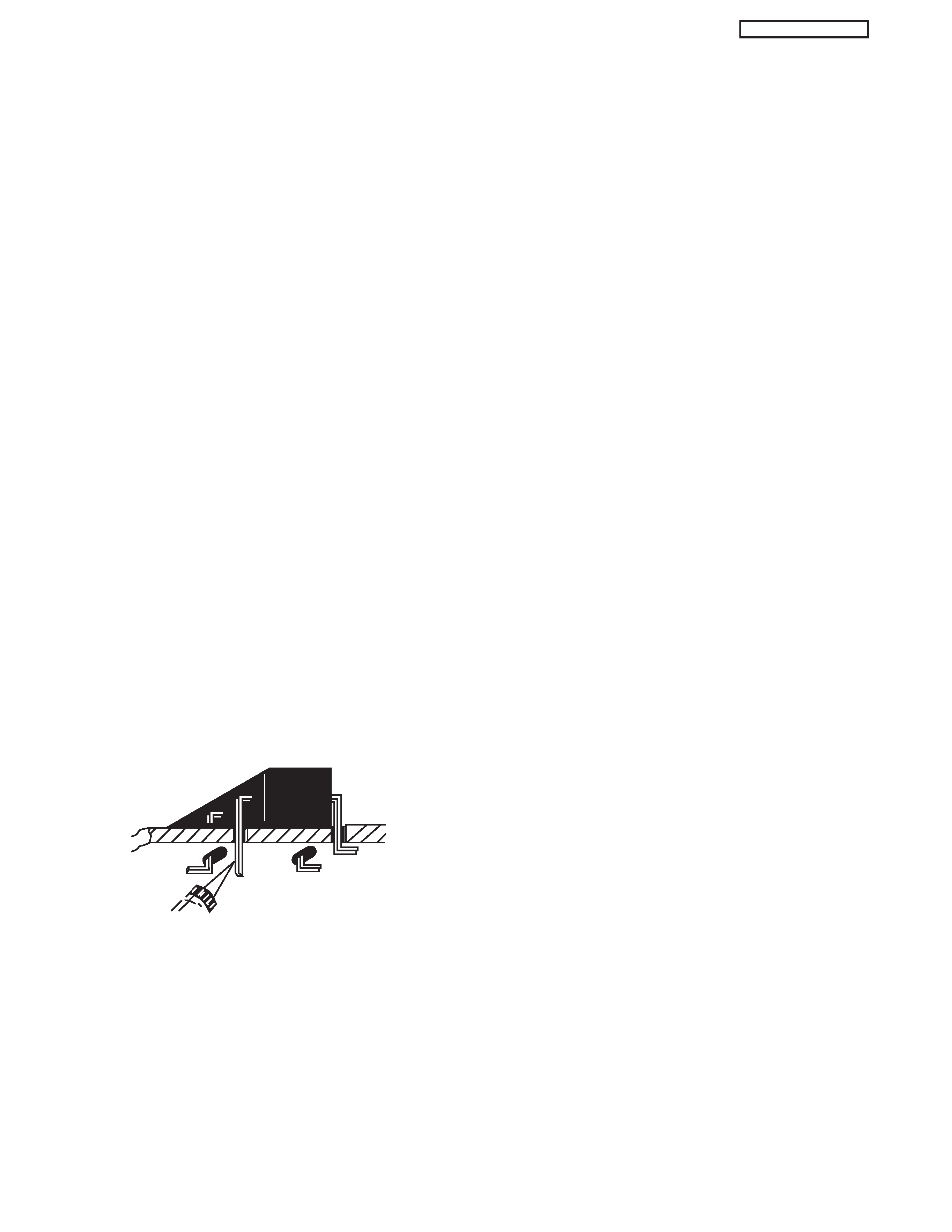
Use Soldering Iron to Pry Leads
IC Removal/Replacement
Some Hitachi unitized chassis circuit boards have slotted
holes (oblong) through which the IC leads are inserted and
then bent flat against the circuit foil. When holes are the
slotted type, the following technique should be used to
remove and replace the IC. When working with boards using
the familiar round hole, use the standard technique as
outlined in paragraphs 5 and 6 above.