In order to achieve maximum performance from
your new Crate Pro Audio Mixer we recommend
that you read this user's guide prior to its use.
User's Guide
for the
CRATE PRO AUDIO
PX700DLX/
PX900DLX
Powered Mixer
with
Digital Signal Processing
2
THIS EQUIPMENT HAS BEEN DESIGNED AND
ENGINEERED TO PROVIDE SAFE AND RELIABLE
OPERATION. IN ORDER TO PROLONG THE LIFE
OF THE UNIT AND PREVENT ACCIDENTAL DAM-
AGES OR INJURY, PLEASE FOLLOW THESE PRE-
CAUTIONARY GUIDELINES:
CAUTION: TO REDUCE THE RISK OF ELECTRIC
SHOCK, DO NOT OPEN CHASSIS; DO NOT
DEFEAT OR REMOVE THE GROUND PIN OF THE
POWER CORD; CONNECT ONLY TO A PROPERLY
GROUNDED AC POWER OUTLET.
WARNING: TO REDUCE THE RISK OF FIRE OR
ELECTRIC SHOCK, DO NOT EXPOSE THIS EQUIP-
MENT TO RAIN OR MOISTURE.
CAUTION:
NO
USER-SERVICEABLE
PARTS
INSIDE. REFER SERVICING TO QUALIFIED SER-
VICE PERSONNEL.
CAUTION: OUR AMPLIFIERS ARE CAPABLE OF
PRODUCING HIGH SOUND PRESSURE LEVELS.
CONTINUED EXPOSURE TO HIGH SOUND PRES-
SURE LEVELS CAN CAUSE PERMANENT HEAR-
ING IMPAIRMENT OR LOSS. USER CAUTION IS
ADVISED AND EAR PROTECTION IS RECOM-
MENDED IF UNIT IS OPERATED AT HIGH VOLUME.
CAUTION
RISK OF ELECTRIC SHOCK
DO NOT OPEN
CAUTION: TO REDUCE THE RISK OF ELECTRIC SHOCK,
DO NOT REMOVE COVER.
NO USER-SERVICEABLE PARTS INSIDE.
REFER SERVICING TO QUALIFIED SERVICE PERSONNEL.
"IT IS NECESSARY FOR THE USER TO REFER TO THE INSTRUCTION MANUAL"
"ES NECESARIO QUE EL USUARIO SE REFIERA AL MANUAL DE INSTRUCCIONES."
"REFERREZ-VOUS AU MANUAL D'UTILISATION"
"UNBEDINGT IN DER BEDIENUNGSANLEITUNG NACHSCHLAGEN"
EXPLANATION OF GRAPHICAL SYMBOLS:
EXPLICACION DE SIMBOLOS GRAFICOS:
"DANGEROUS VOLTAGE"
"VOLTAJE PELIGROSO"
"DANGER HAUTE TENSION"
"GEFAHLICHE SPANNUNG"
=
=
PRECAUCION
RIESGO DE CORRIENTAZO
NO ABRA
PRECAUCION PARA DISMINUOIR EL RIESGO DE CORRIENTAZO
NO ABRA LA CUBIERTA
NO HAY PIEZAS ADENTRO QUE EL USARIO PUEDO REPARAR
DEJE TODO MANTENIMIENTO A LOS TECHNICOS CALIFICADOS
ATTENTION
RISQUE D'ELECTROCUTION
NE PAS OUVRIR
ATTENTION: POUR REDUIRE D'ELECTROCUTION NE PAS
ENLEVER LE COUVERCLE. AUCUNE PIECE INTERNE N'EST REPRABLE
PAR L'UTILISATEUR. POUR TOUTE REPARATION, S'ADRESSER A UN
TECHNICIEN QUALIFIE.
VORSICHT
ELEKTRISCHE SCHLAGGEFAHR
NICHT OFFENEN
VORSICHT: ZUR MINIMIERUNG ELEKTRISCHER SCHLAGGEFAHR NICHT
DEN DECKEL ABENHMEN. INTERNE TEILE KONNEN NICHT VOM
BENUTZER GEWARTET WERDEN. DIE WARTUNG IS QUALIFIZIERTEM
WARTUNGSPERSONAL ZU UBERLASSEN.
ESTE APARATO HA SIDO DISENADO Y CON-
STRUIDO PARA PROVEER ANOS DE OPERACION
SEGURA Y CONFIABLE. PARA PROLONGAR LA
VIDA DE ESTA UNIDAD E IMPEDIR DANOS ACCI-
DENTALES POR FAVOR SIGA ESTAS INSTRUC-
CIONES PREVENTIVAS:
PRECAUCION: PARA DISMINUIR EL RIESGO DE
DESCARGAS ELÉLECTRICAS: (1) NO ABRA LA
CUBIERTA,
(2)
NO
ES
RECOMENDABLE
REMOVER O DESACTIVAR LA PATA DEL POLO A
TIERRA DEL CABLE DE CORRIENTE, CONECTE
CORRECTAMENTE A UNA TOMA DE CORRIENTE
A TIERRA.
ADVERTENCIA: PARA EVITAR DESCARGAS
ELECTRICAS O PELIGRO DE INCENDIO, NO DEJE
ESTE APARATO EXPUESTO A LA LLUVIA O
HUMEDAD.
PRECAUCION: NO HAY PIEZAS ADENTRO QUE
EL USUARIO PUEDE REPARAR. DEJE TODO MAN-
TENIMIENTO A LOS TÉCNICOS CALIFICADOS.
PRECAUCION: NUESTROS AMPLIFICADORES
PUEDEN PRODUCIR NIVELES DE PRESION DE
SONIDO ALTO. EXPOSICION CONTINUADA A LOS
NIVELES DE PRESION DE SONIDO ALTO PUEDE
CAUSA DANO PERMANENTE A SU OIDO. ES
ACONSEJADO QUE USE PRECAUCION AL
USUARIO Y ES RECOMENDADO PROTECCION
PARA LOS OIDOS SI LA UNIDAD ES OPERADA A
VOLUMEN ALTO.
THE CHART BELOW SHOWS THE U.S. GOVERNMENT'S OCCUPATIONAL SAFETY AND HEALTH ADMINISTRATION (OSHA) REGULATIONS WHICH WERE IN EFFECT AT THE TIME OF THIS PUB-
LICATION FOR PERMISSIBLE NOISE EXPOSURE, PER 29CFR1910.95, TABLE G-16:
ACCORDING TO OSHA, ANY EXPOSURE IN EXCESS TO THESE AMOUNTS LISTED ABOVE COULD RESULT IN SOME HEARING LOSS.
SOUND LEVEL DBA,
DURATION PER DAY
SOUND LEVEL DBA,
DURATION PER DAY
SOUND LEVEL DBA,
DURATION PER DAY
SLOW RESPONSE
IN HOURS
SLOW RESPONSE
IN HOURS
SLOW RESPONSE
IN HOURS
90
8
97
3
105
1
92
6
100
2
110
1/2
95
4
102
1 - 1 1/2
115
1/4 or less
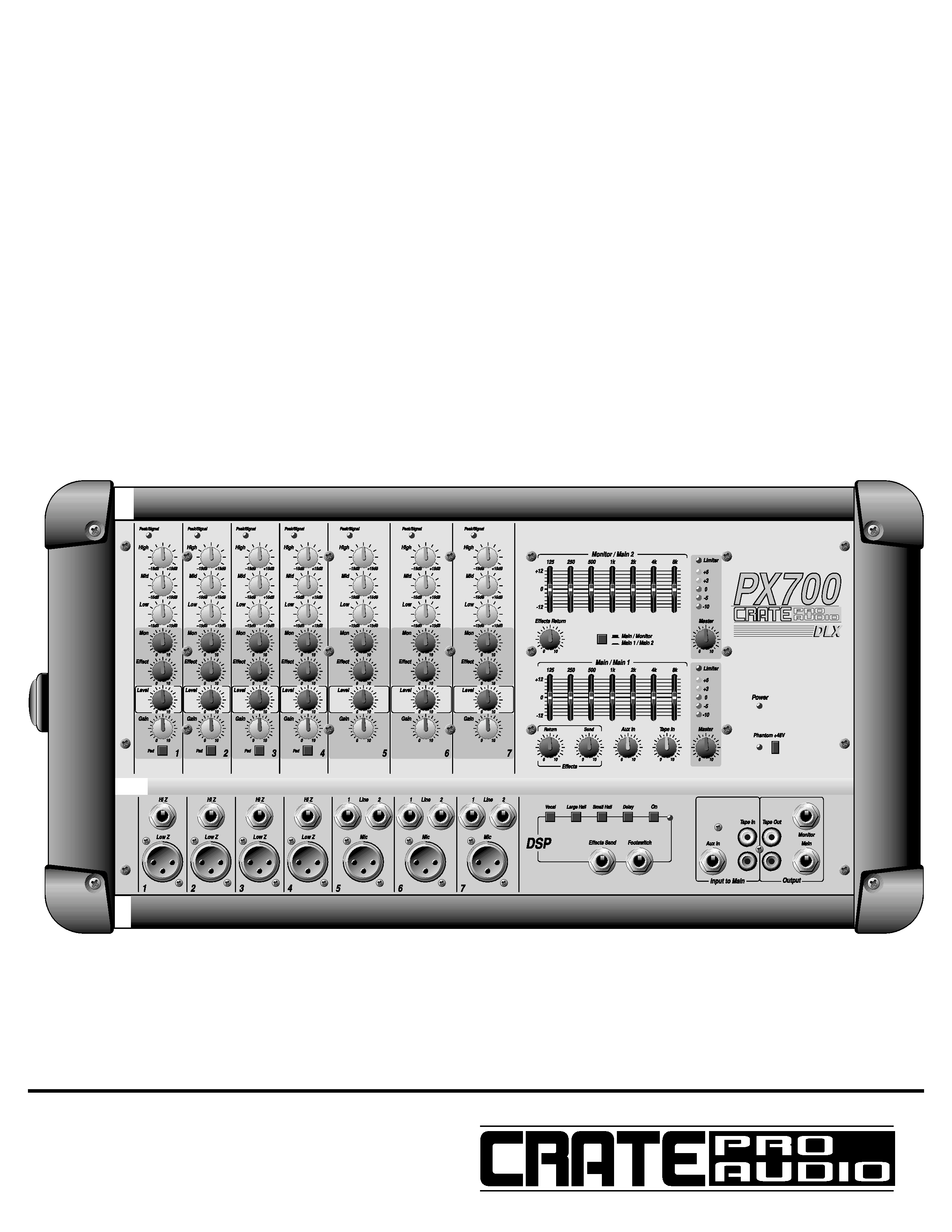
PX700DLX/PX900DLX Powered Mixer
Congratulations.
You are now the proud owner of one of the most compact, user-friendly, and efficient powered mixers available,
the Crate Pro Audio PX700DLX/PX900DLX with Digital Signal Processing. In order to derive the most benefit from the
mixer, and to fully understand and appreciate its flexibility and versatility, please familiarize yourself with the mixer by
reading through this User's Guide prior to its use.
And Thank You, from
Table of Contents:
Features . . . . . . . . . . . . . . . . . . . . . . . . . . . . . . . . . . . . . . . .3
System Block Diagram . . . . . . . . . . . . . . . . . . . . . . . . . . . . .3
The "Mono" Input Channels (1-4) . . . . . . . . . . . . . . . . . . . . .4
The "Stereo" Input Channels (5-7/5-9) . . . . . . . . . . . . . . . . .5
The Master Section . . . . . . . . . . . . . . . . . . . . . . . . . . . . . .6,7
The Rear Panel . . . . . . . . . . . . . . . . . . . . . . . . . . . . . . . . . .7
Technical Specifications . . . . . . . . . . . . . . . . . . . . .back cover

3
PX700DLX/PX900DLX Powered Mixer
Features:
The Input Channels:
· Peak/Signal LEDs for optimum level settings
· Three bands of equalization
· Monitor, effects, and main level controls
· Gain control
· Pad switch (channels 1-4 only) to accommodate "hot" signals
· 1/4" balanced low impedance and XLR balanced high impedance input jacks
· Color coded knobs for ease of reference
The Master Section:
· Separate 7-band graphic eq's for Monitor/Main 2 and Main/Main 1 (switchable)
· Separate Master level controls for Monitor/Main 2 and Main/Main 1 (switchable)
· Built in Limiter to prevent overdriving the amplifiers
· Five-segment LED displays for monitoring the output signals
· Effects send and return controls
· Switchable phantom power
· DSP Digital Signal Processing with on/off switch and four selectable effects
· Footswitch jack for remote control of DSP on/off
· Effects send/aux in jacks for external effects
· Tape in and tape out jacks for recording and play back
· Main and monitor line out jacks
· Color coded knobs for ease of reference
System Block Diagram:
VOCAL
LARGE
HALL
SMALL
HALL
DELAY
ON
HI Z
LOW Z
+48V
LOW MID
EFFECT
HIGH
PHANTOM
POWER
PEAK/
SIGNAL
PAD
GAIN
MAIN
MON
CHANNEL 1-4:
LINE 1
MIC
+48V
LOW MID
EFFECT
HIGH
PHANTOM
POWER
PEAK/
SIGNAL
GAIN
LINE 2
AUX IN
TAPE IN
TAPE IN
AUX IN
MAIN
MON
CHANNEL 5-7/5-9:
TAPE IN
SUM
MAIN
MAIN
EFFECT
EFFECT
MONITOR
MONITOR
INV
BRIDGE
MON/MAIN
3
2
1
3
2
1
6
5
4
B
POWER
AMP 2
MAIN
MASTER
7-BAND
GRAPHIC EQ
POWER
AMP 1
BRIDGE
SPKR OUT
MAIN 1 "A"
SPKR OUT
MAIN 1 "B"
SPKR OUT
MAIN 2 "A"
SPKR OUT
MAIN 2 "B"
SPKR OUT
MAIN
OUT
TAPE
OUT
TAPE
OUT
MAIN/
EFF RTN
LIMITER/
LED
DISPLAY
MON
MASTER
7-BAND
GRAPHIC EQ
MON
OUT
EFFECTS
SEND
FOOT
SWITCH
MON/
EFF RTN
DSP
LIMITER/
LED
DISPLAY
EFFECTS
SEND
6
5
4
B
4
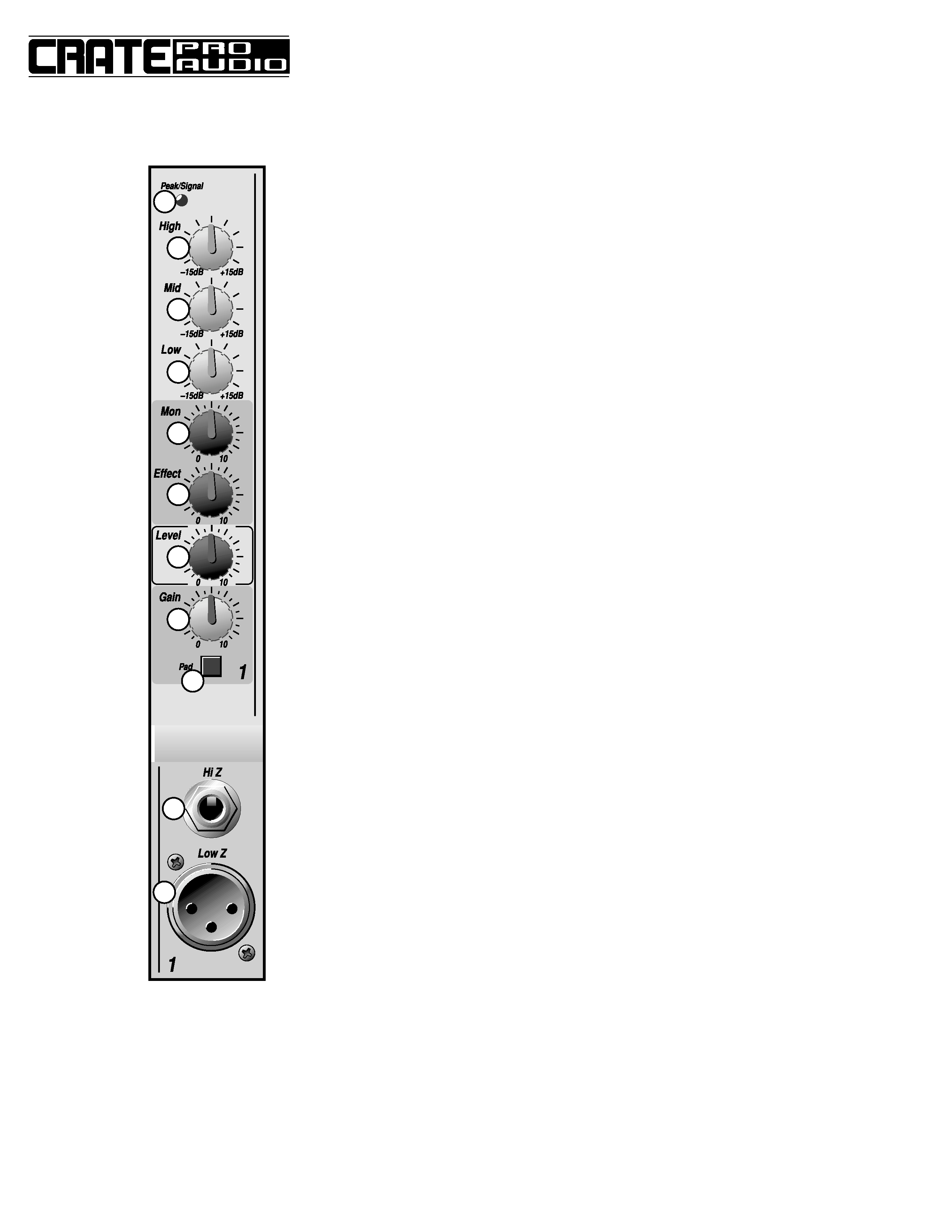
1. PEAK/SIGNAL LED: This LED will illuminate green when a
signal is present at the High or Low Z inputs. When the sig-
nal nears clipping, the LED will illuminate red. (See Gain
control, #8.)
2. HIGH: Use this control to adjust the high frequency level for
the channel. This control allows for 15dB of cut or boost at
12kHz.
3. MID: Use this control to adjust the midrange frequency level
for the channel. This control allows for 15dB of cut or boost
at 2.5kHz.
4. LOW: Use this control to adjust the low frequency level for
the channel. This control allows for 15dB of cut or boost at
80Hz.
5. MON: Use this control to set the amount of the channel's sig-
nal sent to the monitors.
6. EFFECT: Use this control to set the amount of internal DSP
effect (or external effects, if used) to be applied to the chan-
nel.
7. LEVEL: Use this control to set the channel's output signal
level.
8. GAIN: Use this control to set the input signal level for the
channel. Adjust this control so the peak/signal LED (#1)
flashes red on strong signal peaks.
9. PAD: Use this switch to accommodate "hot" input signals.
(Signals too strong to allow a useful setting of the gain con-
trol without causing the peak/signal LED to glow red.)
Depress this switch to engage the 20dB pad, thereby reduc-
ing the input signal's level to a more useable range.
10. HIGH Z INPUT: The signal output from a high impedance
microphone or a line level signal (such as an instrument,
rhythm machine, tape deck, etc.) may be connected here by
means of a shielded cable terminated with a male 1/4" plug.
Tip = "+," ring = "," and sleeve = shield.
11. LOW Z INPUT: The signal output from a low impedance
microphone or a low impedance line level signal (such as a
line out signal from an instrument amplifier) may be con-
nected here by means of a shielded cable terminated with a
male XLR plug. Pin 2 = "+," pin 3 = "," and pin 1 = shield.
PX700DLX/PX900DLX Powered Mixer
The "Mono" Input Channels (1-4):
1
2
3
4
5
6
7
8
9
10
11

5
PX700DLX/PX900DLX Powered Mixer
12. PEAK/SIGNAL LED: This LED will illuminate green
when a signal is present at the High or Low Z inputs.
When the signal nears clipping, the LED will illumi-
nate red. (See Gain control, #19.)
13. HIGH: Use this control to adjust the high frequency
level for the channel. This control allows for 15dB of
cut or boost at 12kHz.
14. MID: Use this control to adjust the midrange fre-
quency level for the channel. This control allows for
15dB of cut or boost at 2.5kHz.
15. LOW: Use this control to adjust the low frequency
level for the channel. This control allows for 15dB of
cut or boost at 80Hz.
16. MON: Use this control to set the amount of the chan-
nel's signal sent to the monitors.
17. EFFECT: Use this control to set the amount of inter-
nal DSP effect (or external effects, if used) to be
applied to the channel.
18. LEVEL: Use this control to set the channel's output
signal level.
19. GAIN: Use this control to set the input signal level for
the channel. Adjust this control so the peak/signal
LED (#12) flashes red on strong signal peaks.
20. LINE 1/LINE 2 INPUTS: The signal output from a
stereo source (such as a stereo instrument, rhythm
machine, tape deck, etc.) may be connected here by
means of a pair of shielded cables, each terminated
with a male 1/4" plug. Tip = "+," ring = "," and sleeve
= shield. The left and right signals are summed inter-
nally to become a mono signal without the need for
external summing devices or adapter cables.
21. MIC INPUT: The signal output from a low impedance
microphone or a low impedance line level signal
(such as a line out signal from an instrument amplifi-
er) may be connected here by means of a shielded
cable terminated with a male XLR plug. Pin 2 = "+,"
pin 3 = "," and pin 1 = shield.
The "Stereo" Input Channels (5-7/5-9):
12
13
14
15
16
17
18
19
20
21