Owner's Manual
for the
BV-60H/BV-120H
All Tube Professional Series
Guitar Amplifiers
by
®
Congratulations!
Your love of performing and driving ambition to be the best have brought you to a turning point in your musical
career: the incredible BV-60H or BV-120H Professional Series guitar amplifier. An all-tube powerhouse of an ampli-
fier designed to take you to the top and keep you there.
We know something about you: we know you were never impressed with those "toys" that some of your friends
called amplifiers. We know you were holding out until someone offered you an American-made, affordable piece
of professional equipment you could really sink your teeth into. A serious amplifier, designed for a serious musi-
cian: an amp with the sounds you've always looked for, the power you've always dreamed about, and the reliabil-
ity you know you'll need. And all with a name you know you can trust: CRATE.
Like all Crate products, your BV-60H/120H is made with pride in America, using only the best components.
Extensive testing at the hands and ears of skilled technicians and musicians insures you that this amplifier is the
absolute best it can be.
In order to get the most out of your new amplifier, we strongly urge you to go over the information contained in
this manual before you begin playing.
And thank you for choosing
Contents:
Introduction . . . . . . . . . . . . . . . . . . . . . . . . . . . . . . . . . . . .3
Features . . . . . . . . . . . . . . . . . . . . . . . . . . . . . . . . . . . . . .3
The Front Panel . . . . . . . . . . . . . . . . . . . . . . . . . . . . . . . . .4
The Rear Panel . . . . . . . . . . . . . . . . . . . . . . . . . . . . . . . . .5
Some Suggested Settings . . . . . . . . . . . . . . . . . . . . . . . . .6
A Word About Tubes . . . . . . . . . . . . . . . . . . . . . . . . . . . . .7
System Block Diagram . . . . . . . . . . . . . . . . . . . . . . . . . . .7
Technical Specifications . . . . . . . . . . . . . . . . . . .back cover
2
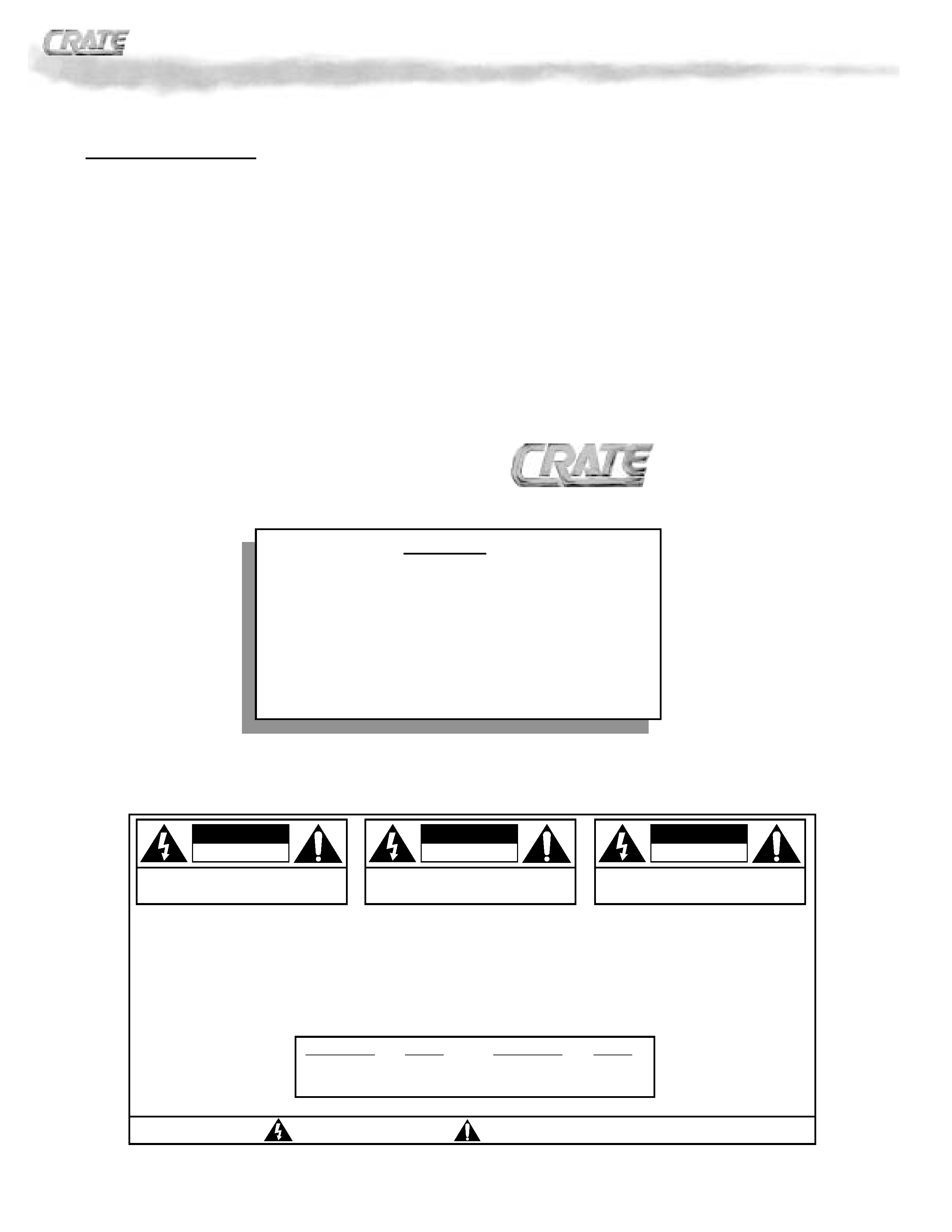
CAUTION
RISK OF ELECTRIC SHOCK
DO NOT OPEN
CAUTION: TO REDUCE THE RISK OF ELECTRIC SHOCK,
DO NOT REMOVE COVER.
NO USER-SERVICEABLE PARTS INSIDE.
REFER SERVICING TO QUALIFIED SERVICE PERSONNEL.
ATTENTION
RISQUE D'ELECTROCUTION
NE PAS OUVRIR
ATTENTION: POUR REDUIRE D'ELECTROCUTION NE PAS
ENLEVER LE COUVERCLE. AUCUNE PIECE INTERNE N'EST REPRABLE
PAR L'UTILISATEUR. POUR TOUTE REPARATION, S'ADRESSER A UN
TECHNICIEN QUALIFIE.
VORSICHT
ELEKTRISCHE SCHLAGGEFAHR
NICHT OFFENEN
VORSICHT: ZUR MINIMIERUNG ELEKTRISCHER SCHLAGGEFAHR NICHT
DEN DECKEL ABENHMEN. INTERNE TEILE KONNEN NICHT VOM
BENUTZER GEWARTET WERDEN. DIE WARTUNG IS QUALIFIZIERTEM
WARTUNGSPERSONAL ZU UBERLASSEN.
THIS EQUIPMENT HAS BEEN DESIGNED AND ENGINEERED TO PROVIDE SAFE AND RELIABLE OPERATION. IN ORDER TO PROLONG THE LIFE
OF THE UNIT AND PREVENT ACCIDENTAL DAMAGES OR INJURY, PLEASE FOLLOW THESE PRECAUTIONARY GUIDELINES:
CAUTION: TO REDUCE THE RISK OF ELECTRIC SHOCK, DO NOT OPEN CHASSIS; DO NOT DEFEAT OR REMOVE THE GROUND PIN OF THE
POWER CORD; CONNECT ONLY TO A PROPERLY GROUNDED AC POWER OUTLET.
WARNING: TO REDUCE THE RISK OF FIRE OR ELECTRIC SHOCK, DO NOT EXPOSE THIS EQUIPMENT TO RAIN OR MOISTURE.
CAUTION: NO USER-SERVICEABLE PARTS INSIDE. REFER SERVICING TO QUALIFIED SERVICE PERSONNEL.
CAUTION: THIS UNIT IS CAPABLE OF PRODUCING HIGH SOUND PRESSURE LEVELS. CONTINUED EXPOSURE TO HIGH SOUND PRESSURE
LEVELS CAN CAUSE PERMANENT HEARING IMPAIRMENT OR LOSS. USER CAUTION IS ADVISED, AND EAR PROTECTION RECOMMENDED IF
UNIT IS OPERATED AT HIGH VOLUME. THE CHART BELOW SHOWS THE U.S. GOVERNMENT'S OCCUPATIONAL SAFETY AND HEALTH ADMINIS-
TRATION (OSHA) REGULATIONS WHICH WERE IN EFFECT AT THE TIME OF THIS PUBLICATION FOR PERMISSIBLE NOISE EXPOSURE, PER
29CFR1910.95, TABLE G-16:
ACCORDING TO OSHA, ANY EXPOSURE IN EXCESS TO THESE AMOUNTS LISTED ABOVE COULD RESULT IN SOME HEARING LOSS.
"IT IS NECESSARY FOR THE USER TO REFER TO THE INSTRUCTION MANUAL"
"REFERREZ-VOUS AU MANUAL D'UTILISATION"
"UNBEDINGT IN DER BEDIENUNGSANLEITUNG NACHSCHLAGEN"
EXPLANATION OF
GRAPHICAL SYMBOLS:
"DANGEROUS VOLTAGE"
"DANGER HAUTE TENSION"
"GEFAHLICHE SPANNUNG"
=
=
SOUND LEVEL DBA,
DURATION PER DAY
SOUND LEVEL DBA,
DURATION PER DAY
SLOW RESPONSE
IN HOURS
SLOW RESPONSE
IN HOURS
90
8
102
1 - 1 1/2
92
6
105
1
95
4
110
1/2
97
3
115
1/4 or less
100
2
® BV-60H/120H All-Tube Professional Series Guitar Amplifiers
®

Introduction:
The BV-60H/120H are all-tube, feature-packed professional stage performers' amplifiers. Rugged con-
struction, reliable American craftsmanship and two powerful channels of pure tube power are some of the
trademarks of these new and impressive pieces of musician's equipment. Both amplifiers feature two dis-
tinctly different 12AX7 tube-driven channels: one with classic tube rhythm sounds and one offering you some
of the finest lead and overdrive sounds of any stock amplifier.
Each channel features an all-tube preamp section with separate reverb level controls and three bands of
equalization for total tone control. The master Presence control lets you custom tailor the sound of your gui-
tar to suit your particular needs. The effects loop can be quickly bypassed via the front panel switch or an
optional footswitch and features a switchable "pad" for use with either floor pedals or rack-mounted effects.
The Line Out signal is tapped directly from the speaker outputs, then attenuated and frequency-compen-
sated to replicate the sound of a miked speaker cabinet. Dual speaker jacks and an impedance selector
switch allow the use of multiple cabinets totalling 8 or 16 ohms. The BV-60H packs a solid 50 watts of out-
put power; the 120H a whopping 100 watts.
Features:
Here's a quick overview of the BV-60H/120H's features and controls. Additional information can
be found on the pages indicated.
· All-Tube Preamp and Power Amp: Classic tube sounds with Crate's legendary performance and
reliability.
· Two Completely Separate Channels: Independent level, tone and reverb controls (page 4).
· Presence Control: Provides even greater tone control and flexibility by allowing you to vary the
upper harmonics of your guitar (page 4).
· Footswitch Control: Remote channel selection and Effects Loop on/off is available through the
use of an optional two-button footswitch (such as Crate's CFP-2) (page 5).
· Switchable Effects Loop with Pad: Footswitch or front panel button controlled, the external
effects loop can be switched in or out with ease. A switchable pad provides optimum performance
from line-level rack mounted effects as well as floor-dwelling foot pedals (pages 4,5).
· Impedance Selector Switch: Proper impedance matching is essential for optimum performance
and life expectancy of a tube amplifier. These amps allow the use of 8 or 16 ohm speaker config-
urations (page 5).
· Line Out Jack: Taken directly from the output of the speaker jacks, the Line Out signal is fre-
quency compensated to sound just like a "miked" speaker cabinet. Use this to connect to the
house mixing board, a recording console or another performer's powered monitor (page 5).
· DC Filament Supply: The first preamp tube has a DC filament supply for reduced hum.
· High Cosmetic Appeal and Stage Presence: The unique cosmetics of the BV-60H/120H serve
as a tribute to your good taste in musical equipment.
· Musician Made in the U.S.A.
3
® BV-60H/120H All-Tube Professional Series Guitar Amplifiers
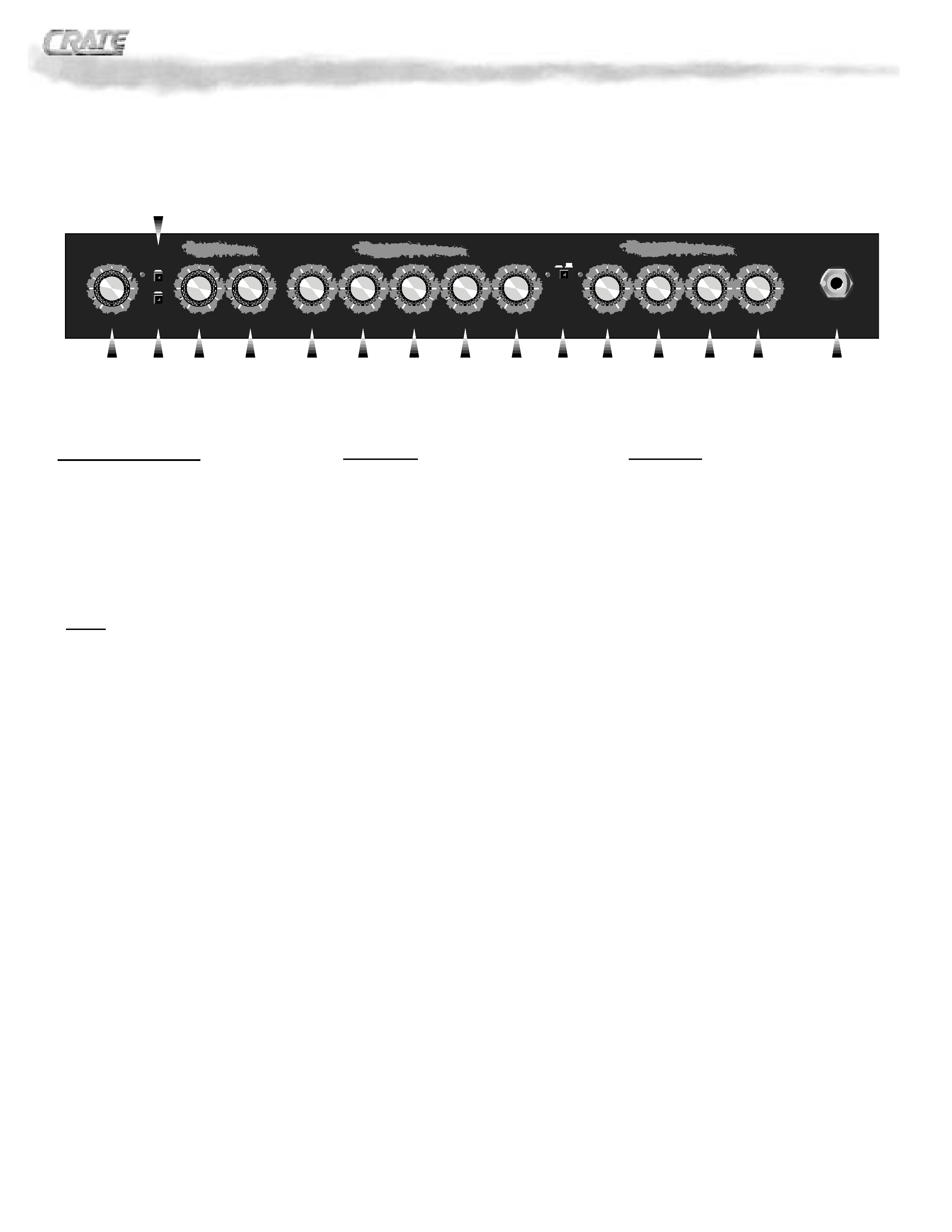
The Front Panel:
1. POWER (not shown): This switch applies
AC voltage to the amplifier, and should always
be turned on first. The switch lights up when
the AC power is on.
2. STANDBY (not shown): This switch acti-
vates the amplifier, and should always be turned
on last. The switch lights up when the high volt-
age power is passing through to the tubes.
NOTE: When you first power up this
amplifier, leave the Standby switch OFF
for at least 20 seconds. This gives the
power tubes a chance to prepare them-
selves for action.
3. PRESENCE: Increase the level of upper har-
monics with this control. The presence control
allows a boost of up to 5dB at 10kHz.
4. EFFECTS LOOP PAD: This switch activates
a 12dB pad on the effects send signal and cor-
responding gain recovery on the return. In the
"out" position the signal is full strength which is
best suited for line level rack mountable effects.
With the switch "in" the signal is lower which is
best suited for foot pedal type effects.
5. EFFECTS LOOP SWITCH: This switch con-
trols the effects return signal of the effects loop.
The loop is only active when the switch is
pressed in. When a footswitch is used, this
switch is disabled. The adjacent yellow LED
glows when the loop is in use.
6,7. REVERB 2, REVERB 1: Adjust the amount
of reverberation on each channel with these
controls: at the "0" position the signal is "dry"
(no reverb). As you bring the control up, the
amount of reverb increases.
Channel 2:
8. MASTER: Set the output signal level of chan-
nel 2 with this control. At the "0" position (full
left) very little or no signal will be heard; as you
bring the control up (towards center) the output
level of channel 2 increases. Use this control
along with your guitar's volume and the channel
2 gain control (#12) to produce a wide variety of
sounds.
9. LOW: Adjust the bottom end response with
this control. The low control covers a range of
15dB at 100Hz. This sets the amount of heard
(and felt) from the amp.
10. MID: Adjust the midrange response with this
control. The mid control covers a range of 13dB
at 500Hz. This controls the "voice" of your gui-
tar.
11. HIGH: Adjust the high end response with
this control. The high control covers a range of
10dB at 10kHz. This controls the "bite" of your
guitar.
12. GAIN: Adjust the overdrive (distortion) level
with this control. With the control towards "0" (to
the left) the signal is relatively clean. As you
bring the control towards "5" (center position)
the distortion increases, along with the overall
output level. Keep turning the control towards
"10" and you'll increase the distortion even
more.
13. CHANNEL SELECT: Switch between chan-
nels with this push-button switch. The adjacent
amber LED glows when channel 1 is selected
(switch "out"), the red LED glows when channel
2 is selected (switch "in"). When a footswitch is
used for channel switching, this switch is dis-
abled.
Channel 1:
14. LOW: Adjust the bottom end response with
this control. The low control covers a range of
16dB at 100Hz. This sets the amount of heard
(and felt) from the amp.
15. MID: Adjust the midrange response with this
control. The mid control covers a range of 20dB
at 300Hz. This controls the "voice" of your gui-
tar.
16. HIGH: Adjust the high end response with
this control. The high control covers a range of
10dB at 10kHz. This controls the "bite" of your
guitar.
17. VOLUME: Set the output volume level of
channel 1 with this control.
18. INPUT: Connect your guitar or wireless
receiver into this standard 1/4" jack using a
shielded instrument cable.
4
Channel 2
CHANNEL
SELECT
CH 2
CH 1
GAIN
MASTER
LOW
MID
HIGH
VOLUME
INPUT
Channel 1
LOW
MID
HIGH
R
everb
REVERB 1
REVERB 2
PRESENCE
EFFECTS LOOP
EFFECTS LOOP PAD
ON
12dB
3
5
4
6
7
8
9
10
11
12
13
14
15
16
17
18
® BV-60H/120H All-Tube Professional Series Guitar Amplifiers
5
125VAC, 50/60Hz
T5A SLO-BLO
250VAC, 50/60Hz
T2.5A SLO-BLO
AC LINE IN
AVIS:
RISQUE DE CHOC ELECTRIQUE.
NE PAS OUVRIR
CAUTION
RISK OF ELECTRIC SHOCK
DO NOT OPEN
WARNING: TO REDUCE THE RISK OF FIRE OR
ELECTRICAL SHOCK, SO NOT EXPOSE THIS EQUIP-
MENT TO RAIN OR MOISTURE.
Made in the U.S.A. by · SLM ELECTRONICS
1400 Ferguson Ave. · St. Louis, MO. 63133
27
26
25
24
23
22
21
20
MAIN
(USE FIRST)
EXT.
SPEAKERS
100 WATTS RMS
LINE OUT
IMPEDANCE
SELECTOR
816
SEND
TIP = CHANNEL SELECT
RING = EFFECTS LOOP
SLEEVE = GROUND
RETURN
EFFECTS
LOOP
FOOTSWITCH
R
TS
T
S
R
19
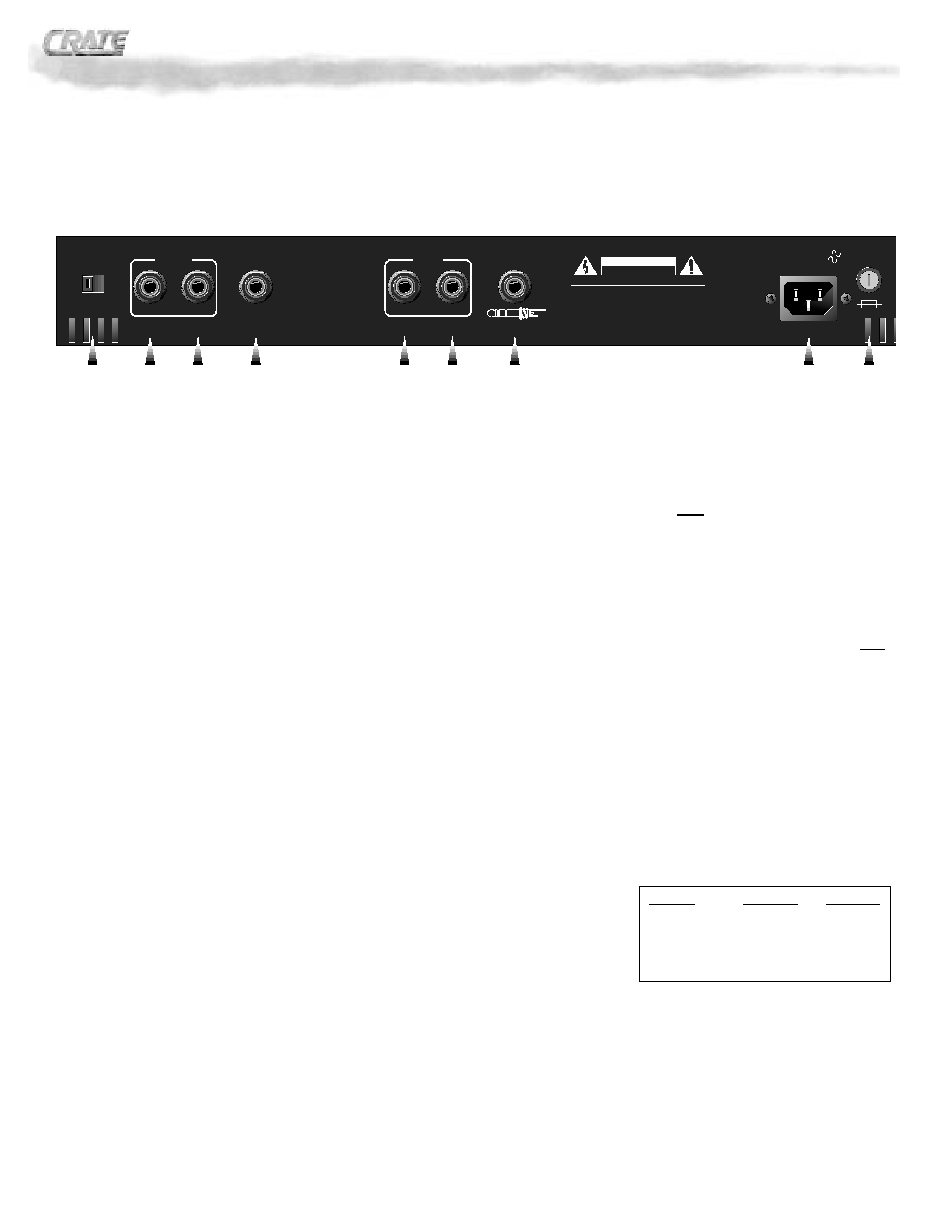
The Rear Panel:
19. FUSE: This fuse protects the amplifier
against damages caused by overload condi-
tions in the unit. If the fuse blows, replace it only
with the same size and type as indicated on the
rear panel. If the fuse blows continually, the line
voltage may be incorrect, or the amp may need
servicing.
20. AC LINE IN: Firmly plug the female end of
the supplied power cord into this socket, push-
ing it in until it is fully seated. Plug the male end
of the cord into a properly grounded AC outlet of
the correct voltage. DO NOT DEFEAT THE
GROUND PIN OF THE AC PLUG! Use only
the supplied power cord. If the amplifier is to be
used outside of the United States, see your
authorized Crate dealer for information about
alternate line cords and power converters if
needed.
21. FOOTSWITCH JACK: Connect a stereo
1/4" (tip/ring/sleeve) here from a two-button
footswitch (such as the Crate CFP-2) for remote
control of channel switching and the effects
loop. The tip of the jack is for the channel
switching; the ring is for the effects loop. When
a footswitch is connected here, the front panel
channel select and effects loop switches are
disabled.
22. EFFECTS LOOP SEND: Connection to an
external effects device is made via this jack.
Connect a shielded instrument patch cord from
the send jack to the input jack of the effect. This
jack is always active. The send jack also dou-
bles as a "preamp out" jack, to feed a post-eq,
pre-amplified signal to a mixing board, record-
ing console or external amplifier.
23. EFFECTS LOOP RETURN: Connection
from an external effects device is made via this
jack. Connect a shielded instrument patch cord
from the output jack of the effect to the return
jack. This jack is active only when the effects
loop is switched in. The return jack also doubles
as a "power amp in" jack, to feed a line-level
signal directly into the BV-60H/120H's internal
power amp. This is useful when "slaving" two
amplifiers together.
24. LINE OUT JACK: This 1/4" jack supplies a
line-level output signal from the power amp for
patching into a mixing board, recording console
or external amplifier. The signal is tapped direct-
ly from the speaker outputs, then attenuated
and electronically compensated to simulate the
sound of a "miked" cabinet.
25. EXT. SPEAKER JACK: Use this jack to
connect the amplifier to a secondary speaker
cabinet, after a speaker has been connected to
the main speaker jack (#26).
26. MAIN SPEAKER JACK: Use this jack to
connect the amplifier to your primary speaker
cabinet. Always keep the impedance at 8 or
16 ohms, with the impedance selector switch
(#27) at the proper setting.
NOTE: Use the MAIN SPEAKER jack first.
Then, if an extension speaker is desired,
connect it to the EXT. SPEAKER jack.
27. IMPEDANCE SELECTOR: For the best
performance and least strain on your amplifier,
you MUST properly match the impedance of
your amplifier to that of your speaker cabinet(s).
Set the selector switch to the 8 or 16 ohm posi-
tion, depending on the total impedance of your
speaker cabinet(s). The chart below can help
you determine that impedance based on the fol-
lowing combinations of speakers connected in
parallel.
CAB. IMP.
# OF CABS.
TOTAL IMP.
8 OHMS
1
8 OHMS
16 OHMS
1
16 OHMS
16 OHMS
2
8 OHMS
32 OHMS
2
16 OHMS
32 OHMS
4
8 OHMS
® BV-60H/120H All-Tube Professional Series Guitar Amplifiers