
R
(with price)
Page
Specifications............................................................................................. 1
Block Diagram ........................................................................................... 2
Circuit Description ...................................................................................... 3
Adjustment
Linear PCB .......................................................................................... 5
A/D PCB .............................................................................................. 9
Troubleshooting ....................................................................................... 10
Printed Circuit Boards .............................................................................. 11
Wiring Diagram ........................................................................................ 15
Exploded View / Disassembly .................................................................. 16
Electrical Parts List .................................................................................. 17
Mechanical Parts List............................................................................... 23
IC and Transistor Lead Identification ....................................................... 24
Schematic Diagrams and Waveforms ..................................................... 26
DECEMBER 1994
TV-600C
TV-600D
TV-600I
TV-600N
POCKET TELEVISION
INDEX

file:///C|/Documents%20and%20Settings/bob/My%20Documents/manualdirectory.htm
This file was downloaded and provided FREE OF CHARGE
from the ManualDirectory community.
You can find many free to download Service Manuals & Schematics at
http://www.manualdirectory.co.uk
file:///C|/Documents%20and%20Settings/bob/My%20Documents/manualdirectory.htm01/04/2007 01:34:00
SPECIFICATIONS
-- 1 --
Item
Specification
1.
Reception channels
VHF : 2 ~ 13 ch
UHF : 14 ~ 69 ch
2.
Power voltage
DC 6.0 V
3.
Power consumption
Approx. 3.4 W
4.
Current consumption
Approx. 566 mA
5.
Battery life (with alkaline batteries)
Approx 3.0 hours
Batteries
: 4 AA size batteries
6.
Power supply
Car adaptor : CA-K65
AC adaptor : ADK-65, 64
Earphone jack
: 3.5ø mini
7.
Connection terminals
External power jack
: 6.0V DC IN
External antenna jack
: 3.5ø mini
Audio / Video jack
: 3.5ø
8.
Screen size
2.2 inches
9.
No. of Picture element
39,600 (110
× 360) dots
10.
Dimensions
81 (W)
× 32 (D) × 131 (H) mm
3 1/5" (W)
× 1 1/4" (D) × 5 1/6" (H)
11.
Weight
220 g excepting batteries
7.8 oz excepting batteries
12.
Standard accessories
Test batteries (R6
× 4)
AC adaptor
: AD-K65, 64
13.
Options
Car adaptor
: CA-K65
RF connector
: CF-13
Antenna matching device : AS-35S
14.
Body color
Black
-- 2 --
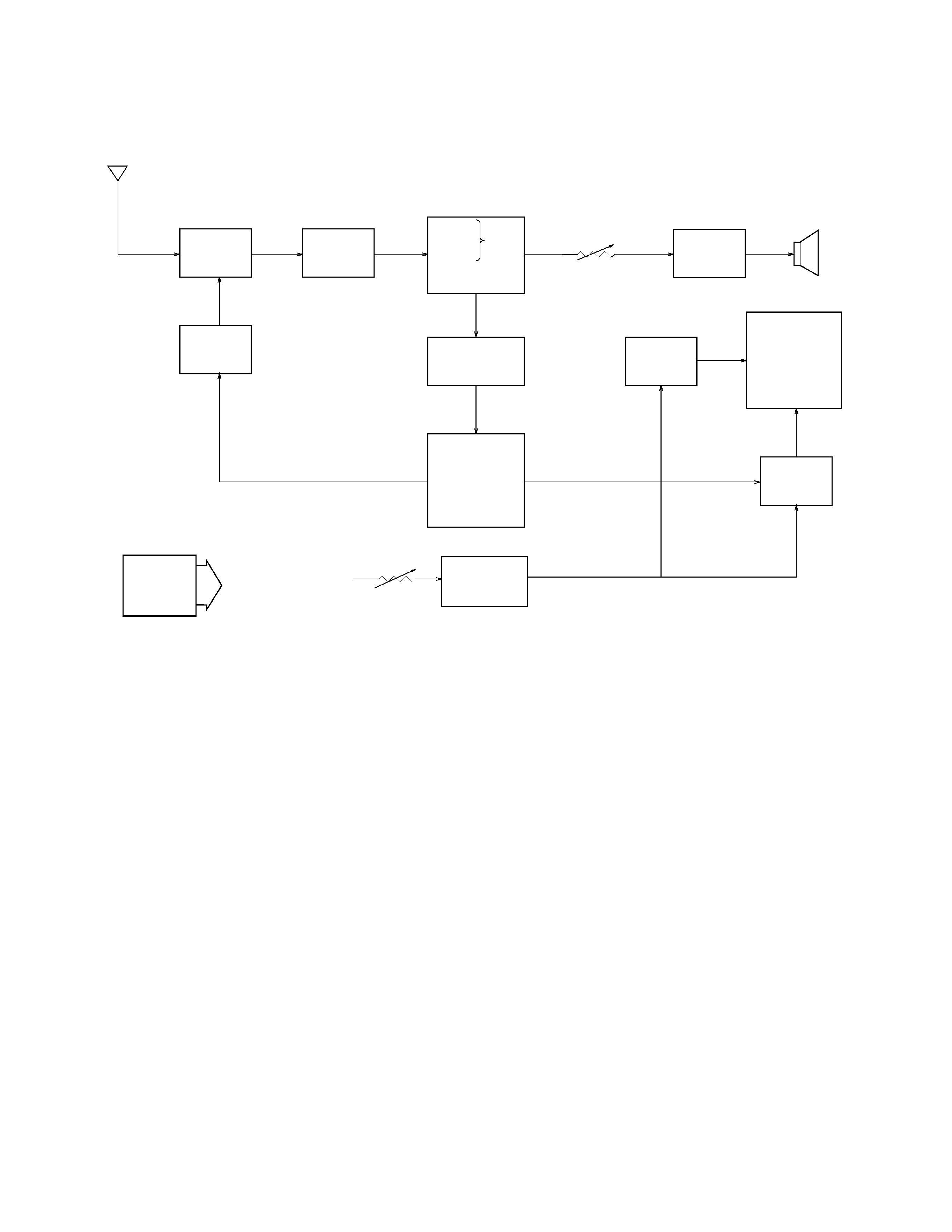
Antenna
1 TU200
2 Q200
3 IC200
7
Tuning
Voltage
Generator
VR600
Volume
Control
4 IC600
Speaker
IC300
IC700
Common
Driver
LCD
Segment
Driver
Chroma
Circuit
Osc.
Display
Control
A-D Converter
Auto-Tuning
Control
5
6
8 Q800~Q802, Q804~Q806
VR800
Display
Voltage
Generator
Brightness
Control
VCC2 (3.95
±0.02 V)
VCC6 (30.5~39.0 V)
VCC7 (53.5~72.5 V)
VEE1 (6.3~7.9 V)
IC500
Power
Supply
Audio
Amp.
IF Amp.
Tuner
Video
Sound
Det.
FM
AFT Circuit
AGC Circuit
Det
1
-- Color Tuner: TU200 TEPU5-02
Selects a desired radio wave and changes it to the video IF signal.
2
-- Video IF Amp.: Q200 2SC4238
Amplifies the video IF signal output from the tuner TU by 10 times (20 dB).
3
-- Video Det./Sound Det./FM Det./AFT/AGC: IC200 M51348FP
Eliminates the carrier wave in the video IF signal, and picks up the video signal and the sound IF signal.
Also, the sound signal is picked up from the sound IF signal by FM detection.
4
-- Audio Amp.: IC600 NJM2070M
Sound amplification.
5
-- Chroma Circuit: IC300 M52042FP
Generates the tricolor (red, green, and blue) from the video signal.
6
-- Osc./A-D Converter/Display Control/ Auto-Tuning Control : IC700 MSM6625-02 GSK-640F
Converts the color signal into a digital signal.
Also, generates the clock pulse for the display and controls the display.
7
-- Tuning Voltage Generator: IC500 MSC1169MS-K
Generates the tuning voltage with the tuning pulse (TU) output from 6
.
8
-- Display Voltage Generator: Q800~Q802, Q804~Q806, 2SD601A-R x 4, 2SB709A-R, 2SD1149-S
Generates the display voltages V0 ~ V4 with VEE1 and VCC7 outputs from the power supply.
BLOCK DIAGRAM
-- 3 --
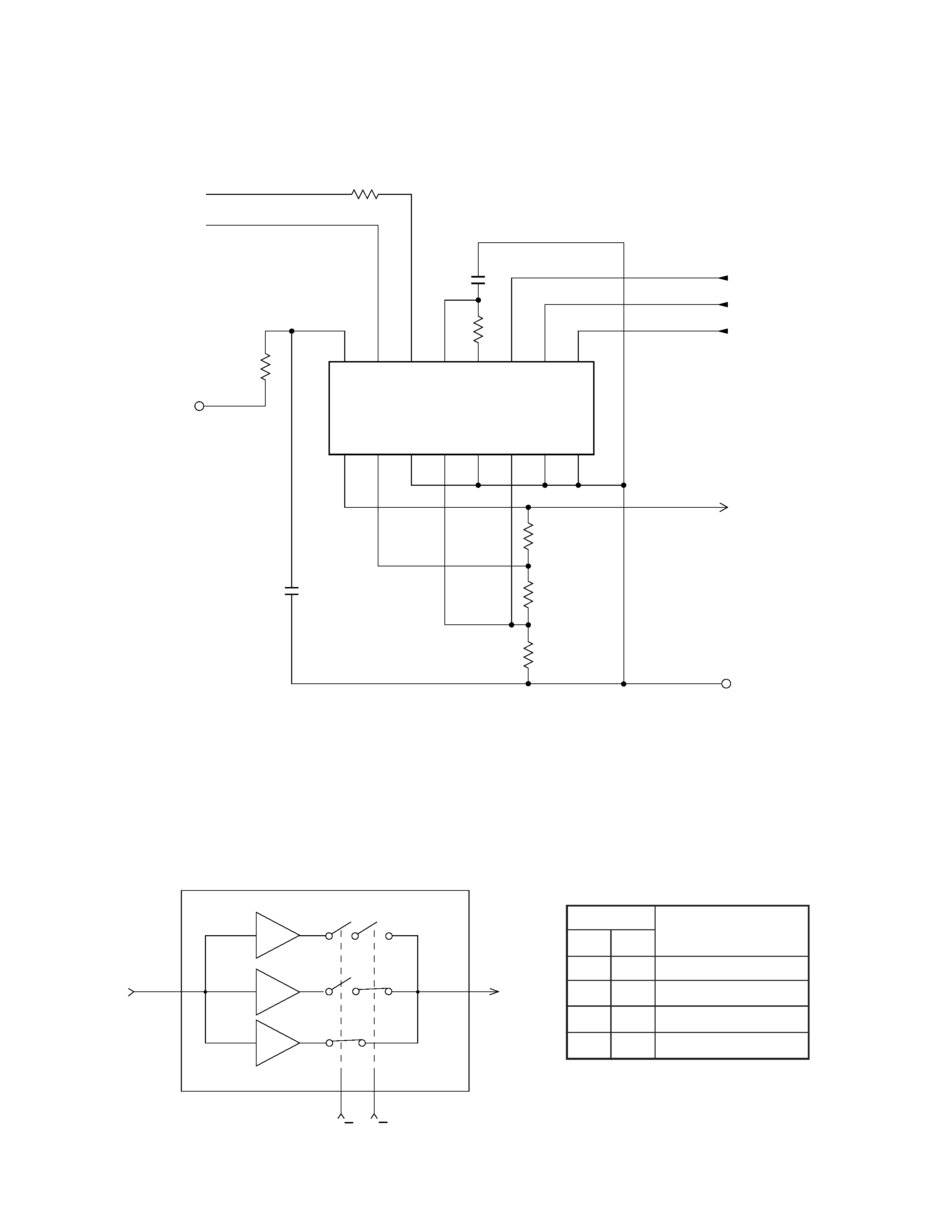
BT
BS
VCC6
TU
H/L
BU
VREF
GND
16
15
14
13
12
11
10
9
1
2
3
4
5
6
7
8
Vcc
BS
BT
IN
OUT
TU
H/L
U/V
VREF
U1
U2
VL1
VL2
VH1
VH2
GND
R500
R501
R502
IC500 MSC1169MS-K
Function
CIRCUIT DESCRIPTION
TUNING VOLTAGE GENERATOR
Table 1
Figure 2
Figure 1
This circuit generates the DC tuning voltage BT for selecting a channel with a TU pulse being output from
IC700.
IC500 has 3 circuits for converting pulses to voltages; it selects one of VHF-L, VHF-H, or UHF, and
causes the tuning voltage to be output from the OUT terminal (pin 12). Figure 2 and Table 1 show the
conditions for selection.
IC500
TU
OUT(BT)
U/V H/L
VHF
-H
UHF
VHF
-L
11
910
12
U/V
L
L
H
H
H/L
L
H
L
H
Inputs
VHF-L receiving
VHF-H receiving
UHF receiving
UHF receiving