
R
(with price)
Page
Specifications............................................................................................. 1
Block Diagram ........................................................................................... 2
Adjustment
Linear PCB .......................................................................................... 3
PCB ........................................................................................................... 8
Wiring Diagram ........................................................................................ 10
Electrical Parts List .................................................................................. 11
Mechanical Parts List............................................................................... 18
Exploded View / Disassembly .................................................................. 19
IC and Transistor Lead Identification and Internal Circuitry ..................... 20
Schematic Diagrams and Waveforms ..................................................... 23
POCKET TELEVISION
SEPTEMBER 1994
TV-5100D
INDEX

SPECIFICATIONS
Item
Specification
1.
Reception channels
VHF : --
UHF : 21 ~ 68 ch
2.
Power voltage
DC 6.0 V
3.
Power consumption
Approx. 3.0 W
4.
Current consumption
Approx. 500 mA
5.
Battery life (with alkaline batteries)
Approx. 2.0 hours
Batteries
: 4 AA size batteries
6.
Power supply
Car adaptor : CA-K65
AC adaptor : AD-K65
Earphone jack
: 3.5ø mini
7.
Connection terminals
External power jack
: 6.0 V DC IN
External antenna jack : 3.5ø mini
Audio / Video jack
: 3.5ø
8.
Screen size
1.8 inches
9.
No. of Picture element
61,380 (220
× 279) dots
10.
Dimensions
92 mm (H)
× 105 mm (W) × 80 mm (D)
3-11/16" (H)
× 4-1/5" (W) × 3-1/5" (D)
11.
Weight
290 g excepting batteries
10.2 oz excepting batteries
12.
Standard accessories
Test batteries (R6 x 4)
13.
Options
AC adaptor
: AD-K65
Car adaptor
: CA-K65
RF connector
: CF-13
Antenna matching device : AS-35S
14.
Body color
Black
-- 1 --
-- 2 --
1
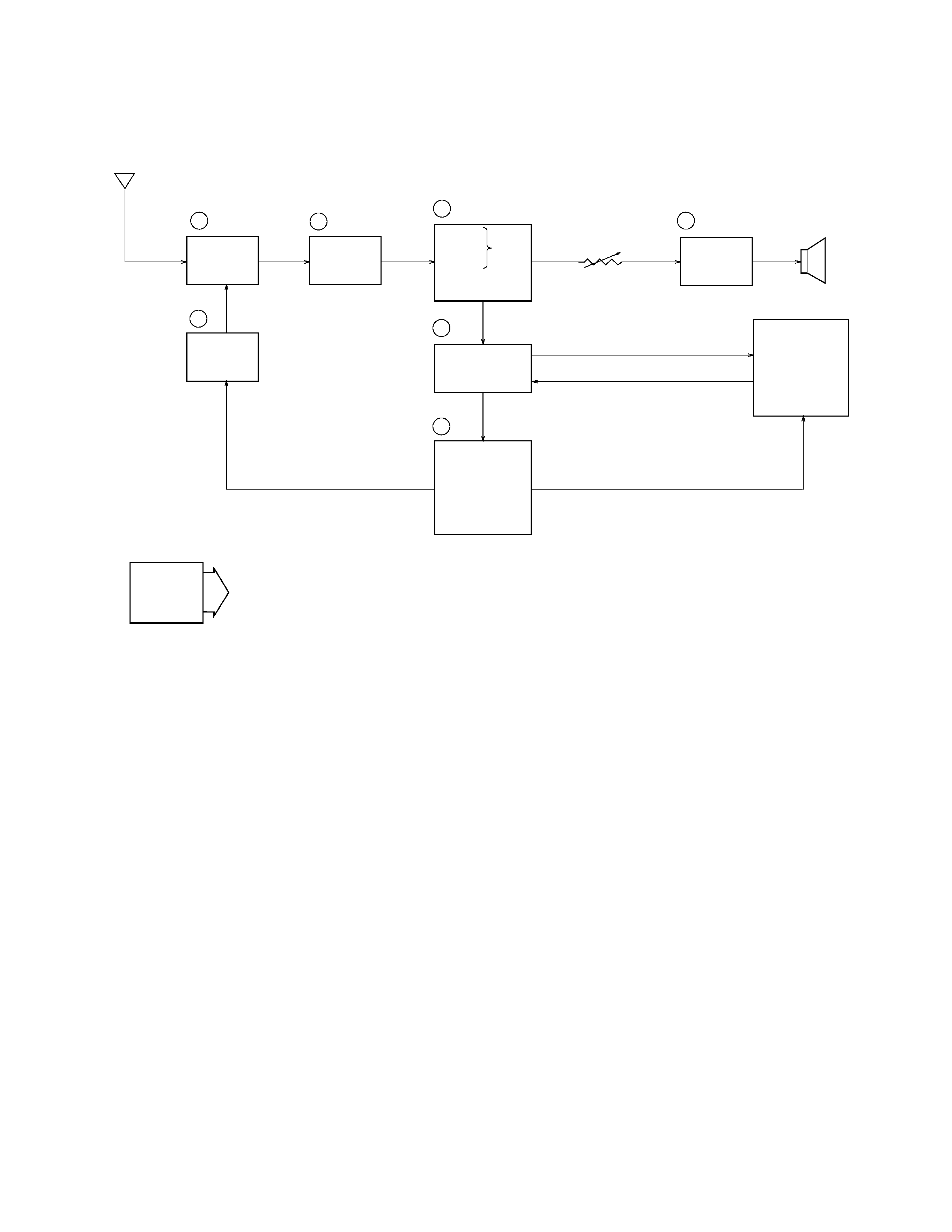
-- Color Tuner: TU200 TEPB5-02
Selects a desired radio wave and changes it to the video IF signal.
2
-- Video IF Amp.: Q200 2SC4670
Amplifies the video IF signal output from the tuner TU by 10 times (20 dB).
3
-- Video Det./Sound Det./FM Det./AFT/AGC: IC200 M51348FP
Eliminates the carrier wave in the video IF signal, and picks up the video signal and the sound IF signal.
Also, the sound signal is picked up from the sound IF signal by FM detection.
4
-- Audio Amp.: IC600 NJM2070M
Sound amplification.
5
-- Chroma Circuit: IC300 IR3P96B
Generates the tricolor (red, green, and blue) from the video signal.
6
-- Display Control/ Auto-Tuning Control : IC700 MSM6770GS
Controls the display.
7
-- Tuning Voltage Generator: IC270 BA10358F
Generates the tuning voltage with the tuning pulse (TU) output from 6.
BLOCK DIAGRAM
Antenna
1
TU200
2
Q200
3
IC200
7
Tuning
Voltage
Generator
VR600
Volume
Control
4
IC600
Speaker
IC300
IC700
LCD
Chroma
Circuit
Display
Control
Auto-Tuning
Control
5
6
VCC2 (4.5±0.02V)
VCC7 (26.5~31.3V)
VCC6 (10.8~12.5V)
VEE1 (8.5~7.5V)
VEE2 (19.8~17.2V)
IC270
Power
Supply
Audio
Amp.
IF Amp.
Tuner
Video
Sound
Det.
FM
AFT Circuit
AGC Circuit
Det
-- 3 --
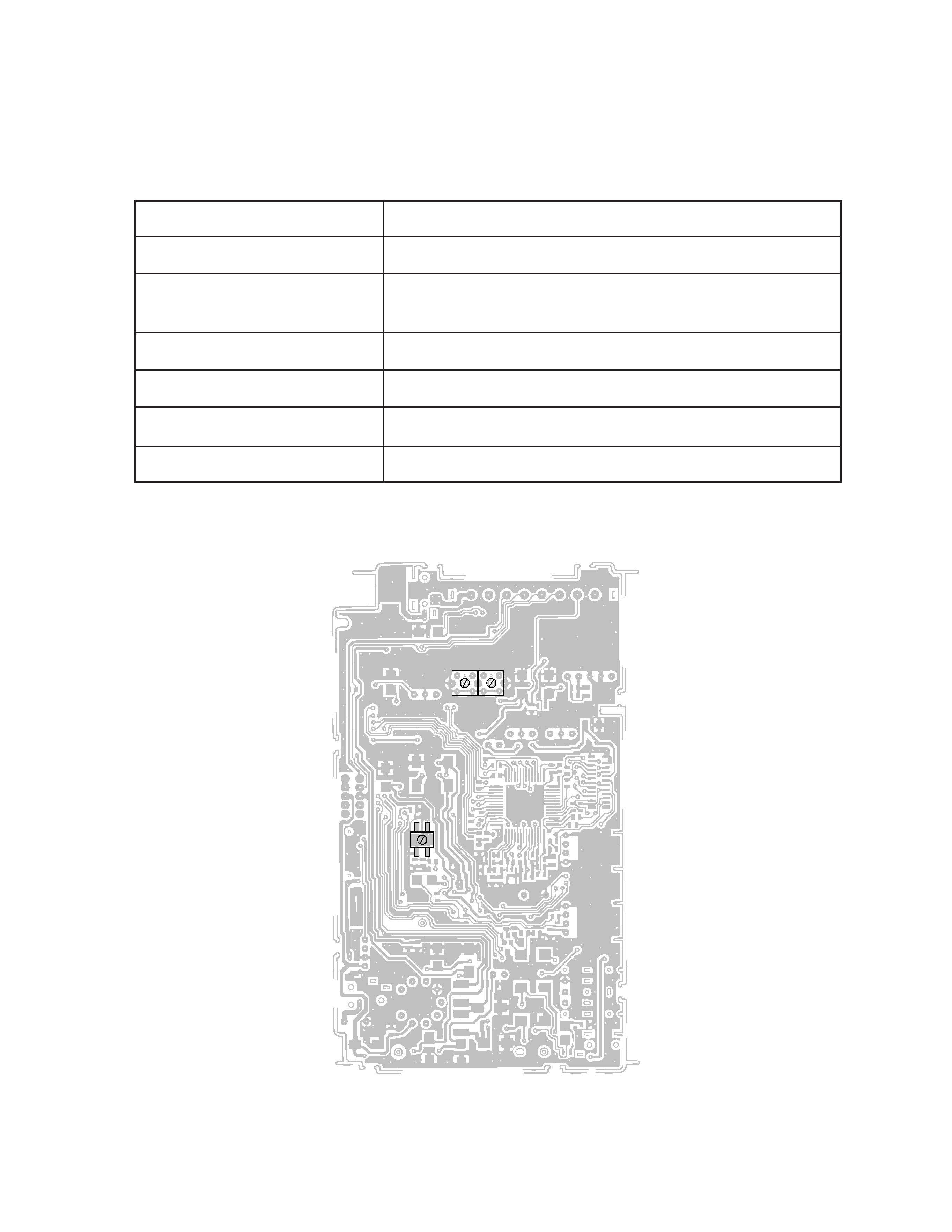
Adjustment And Test Point Locations
Top View
ADJUSTMENT
LINEAR PCB
Items To Be Adjusted
Item
Measuring Instrument
VCC2-1 voltage setting
Voltmeter
Video detection coil adjustment
TV signal generator, pattern generator, oscilloscope,
low-pass filter
AFT coil adjustment
Sweep generator, oscilloscope, voltmeter
Contrast adjustment
TV signal generator, pattern generator, oscilloscope
AGC adjustment
TV signal generator, pattern generator, IF levelmeter
Clock adjustment
Voltmeter
T201
T200
T300
-- 4 --
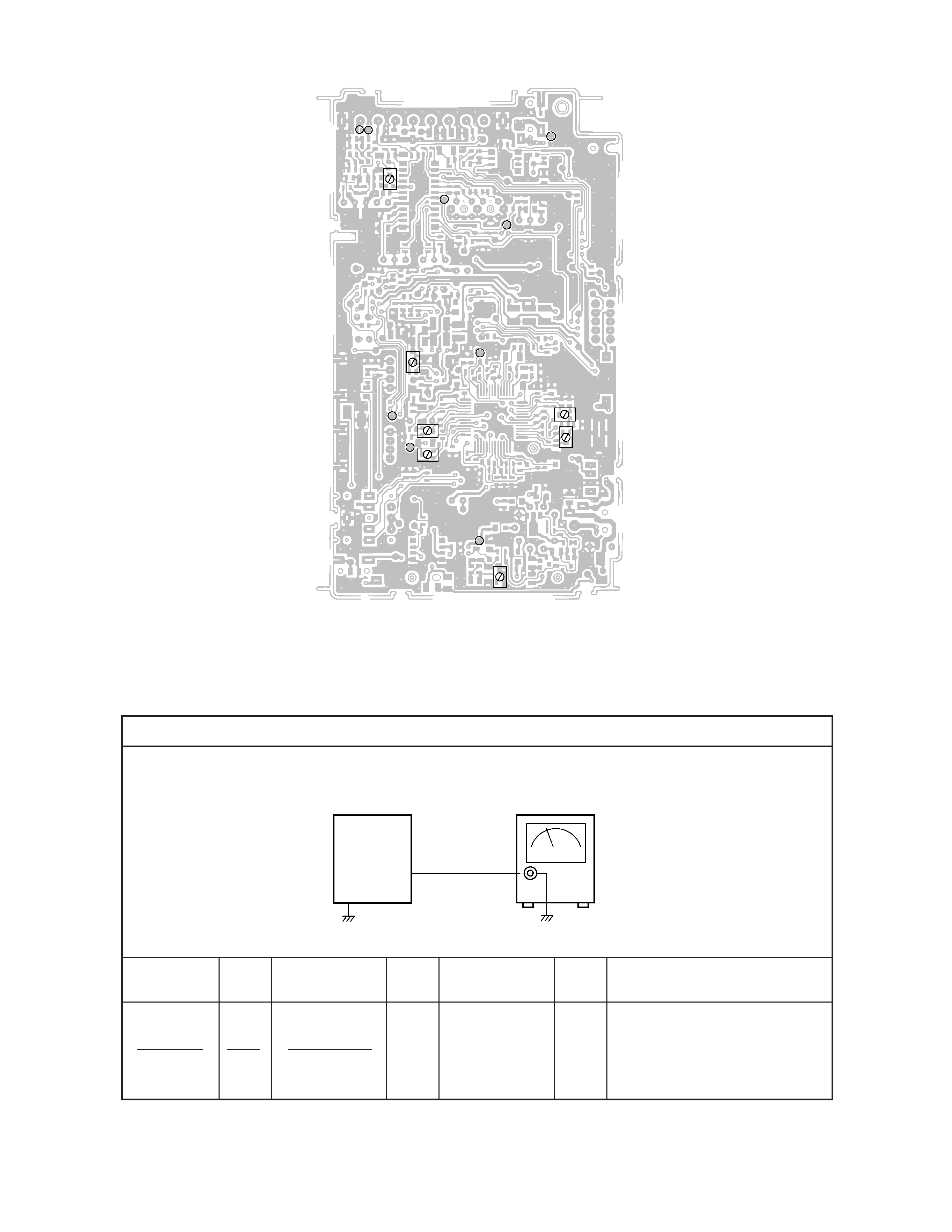
VCC2-1 Voltage Setting
Input
Input
Input
Output
Output
Connection Point
Signal
Connection
Point
Adjust
Result
Adjust for 4.50
± 0.02 V
reading on voltmeter.
Voltmeter
VR100
Set
Output
Voltmeter
TP1
TP1
TV-5100
Equipment Connection / Adjustment Procedure
Bottom View
VR100
TP4
TP3
TP6
TP7
TP5
TP8
TP1
VR300
VR748
VR204
VR303
VR302
Pad IF
TP2
VR301