
R
(with price)
POCKET TELEVISION
TV-350C
OCTOBER 1994
Page
Specifications............................................................................................. 2
Block Diagram ........................................................................................... 3
Adjustment
Linear PCB ......................................................................................... 4
Printed Circuit Boards ................................................................................ 8
Wiring Diagram ........................................................................................ 10
Electrical Parts List .................................................................................. 11
Mechanical Parts List............................................................................... 17
Exploded Views / Disassembly ................................................................ 18
Schematic Diagrams and Waveforms ..................................................... 19
INDEX

file:///C|/Documents%20and%20Settings/bob/My%20Documents/manualdirectory.htm
This file was downloaded and provided FREE OF CHARGE
from the ManualDirectory community.
You can find many free to download Service Manuals & Schematics at
http://www.manualdirectory.co.uk
file:///C|/Documents%20and%20Settings/bob/My%20Documents/manualdirectory.htm01/04/2007 01:34:00

-- 2 --
SPECIFICATIONS
Item
Specification
Reception Channels
VHF: Ch 2 ~ 12 ch
UHF: Ch 21 ~ 69
Power Voltage
DC 6.0 V
Power Consumption
Approx. 3.0 W
Current Consumption
Approx. 500 mA
Battery Life (with alkaline batteries)
Approx. 3.0 hours
Batteries
: 4 AA size batteries
Power Supply
Car adaptor : CA-K65
AC adaptor : AD-K65
Connection Terminals
Earphone jack
: 3.5ø mini
External power jack
: 6.0 V DC IN
Screen Size
1.6 inches
No. of Picture Element
39,600 (110
× 360) dots
Dimensions
122 mm (H)
× 66 mm (ø)
Weight
210 g excluding batteries
7.4 oz excluding batteries
Options
AC adaptor :
AD-K65
Car adaptor :
CA-K65
-- 3 --
Antenna
1
TU200
2
Q200
3
IC200
7
Tuning
Voltage
Generator
VR600
Volume
Control
4
IC600
Speaker
IC300
IC700
Common
Driver
LCD
Segment
Driver
Chroma
Circuit
OSC
Display
Control
A-D Converter
Auto-Tuning
Control
5
6
8
Q800 ~ Q806
VR800
Display
Voltage
Generator
Brightness
Control
VCC2 (3.95V±0.02V)
VCC6 (30.5 ~ 39.0V)
VCC7 (53.5 ~ 72.5V)
VEE1 (-6.3 ~ -7.9V)
IC500
Power
Supply
Audio
Amp.
IF Amp.
Tuner
Video
Sound
Det.
FM
AFT Circuit
AGC Circuit
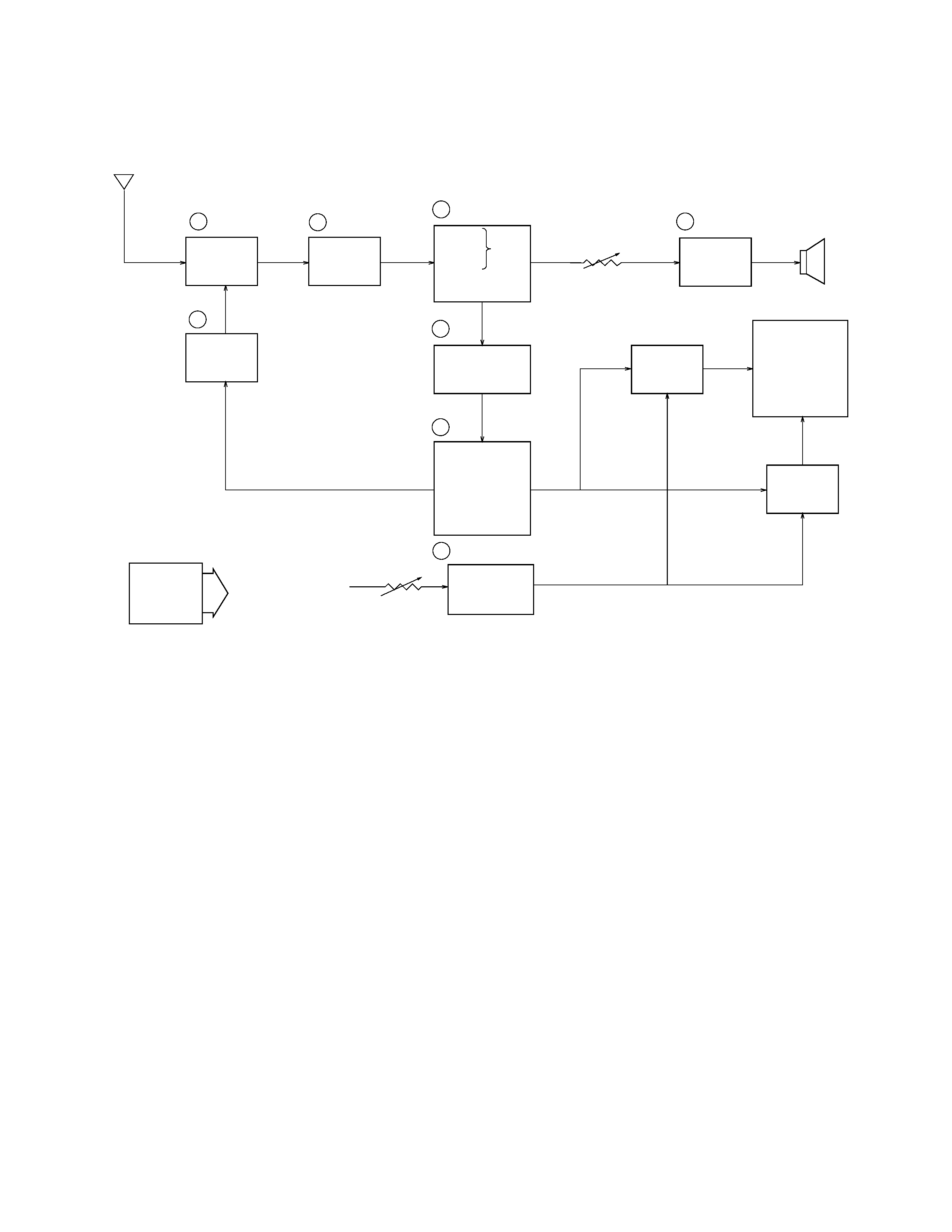
BLOCK DIAGRAM
1
-- Color Tuner: TU200 TEPE5-01
Selects a desired radio wave and changes it to the video IF signal.
2
-- Video IF Amp.: Q200 2SC4238
Amplifies the video IF signal output from the tuner TU by 10 times (20dB).
3
-- Video Det./Sound Det./FM Det./AFT/AGC: IC200 M51348FP
Eliminates the carrier wave in the video IF signal, and picks up the video signal and the sound IF signal.
Also, the sound signal is picked up from the sound IF signal by FM detection.
4
-- Audio Amp.: IC600 NJM2070M
Sound amplification.
5
-- Chroma Circuit: IC300 M52045FP
Generates the tricolor (red, green, and blue) from the video signal.
6
-- OSC/A-D Converter/Display control/ Auto-Tuning Control : IC700 MSM662502 GSK-640F
Converts the color signal into a digital signal.
Also, generates the clock pulse for the display and controls the display.
7
-- Tuning Voltage Generator: IC500 MSC1169MS-K
Generates the tuning voltage with the tuning pulse (TU) output from 6.
8
-- Display Voltage Generator: Q800 ~ Q806 2SB1218A-R, 2SD1824R, S
× 2, 2SD1819A-R × 5,
2SD1824-5
Generates the display voltages V0 ~ V4 with VEE1 and VCC7 outputs from the power supply.
-- 4 --
ADJUSTMENT
Linear PCB
1) Items to Be Adjusted
Item
Measuring Instrument
VCC2 voltage setting
Voltmeter
Video detection coil adjustment
TV signal generator, Pattern generator, Oscilloscope,
Low-pass filter
AFT coil adjustment
Sweep generator, Oscilloscope, Voltmeter
Contrast adjustment
TV signal generator, Pattern generator, Oscilloscope
AGC adjustment
TV signal generator, Pattern generator, IF levelmeter
Clock adjustment
Voltmeter
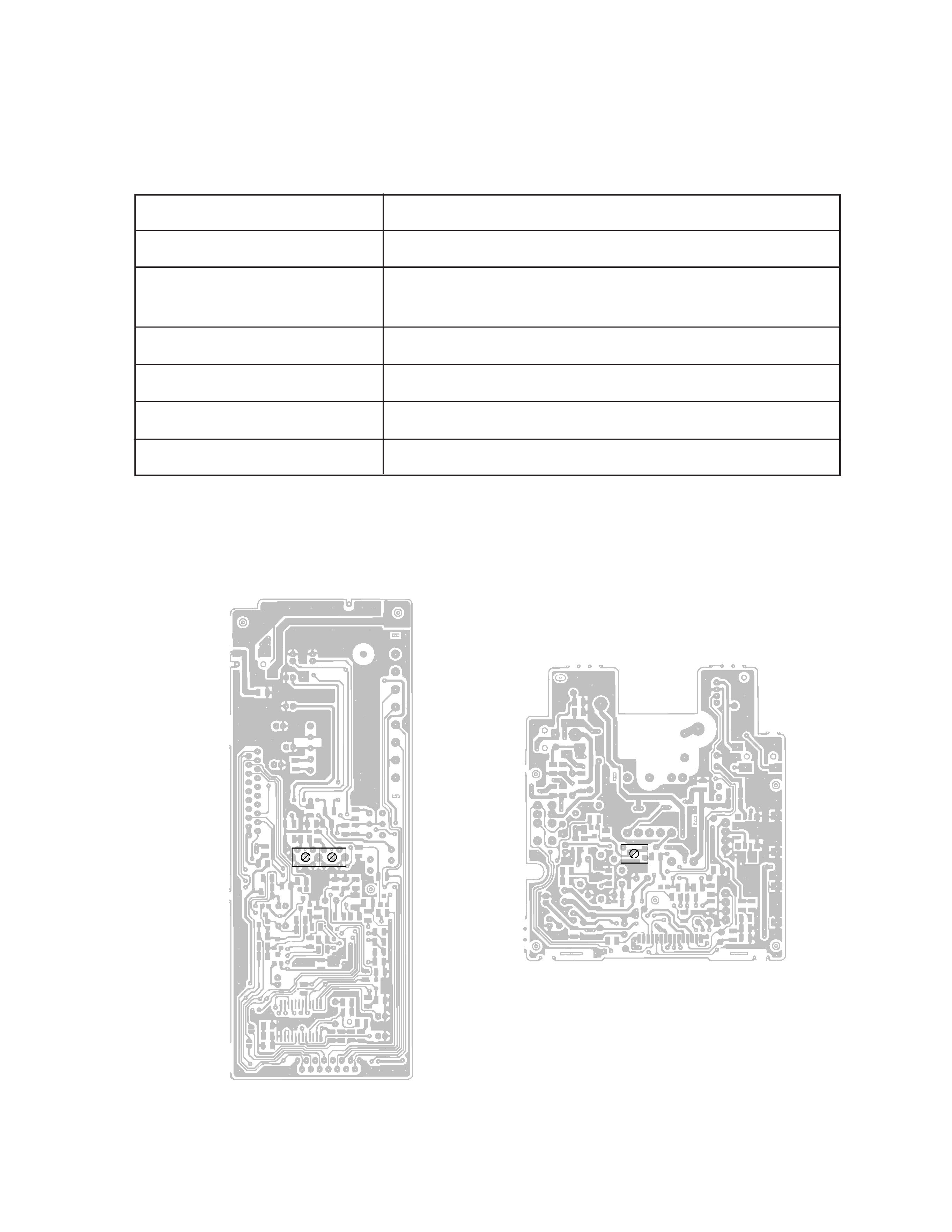
2) Adjustment and Test Point Locations
TOP VIEW
T201 T200
VR100