
QW-1455
MODULE NO.
R
REF. NO. S/M-523
APRIL 1996
BG-300B
SERVICE MANUAL
& PARTS LIST
(WITHOUT PRICE)
-- 1 --
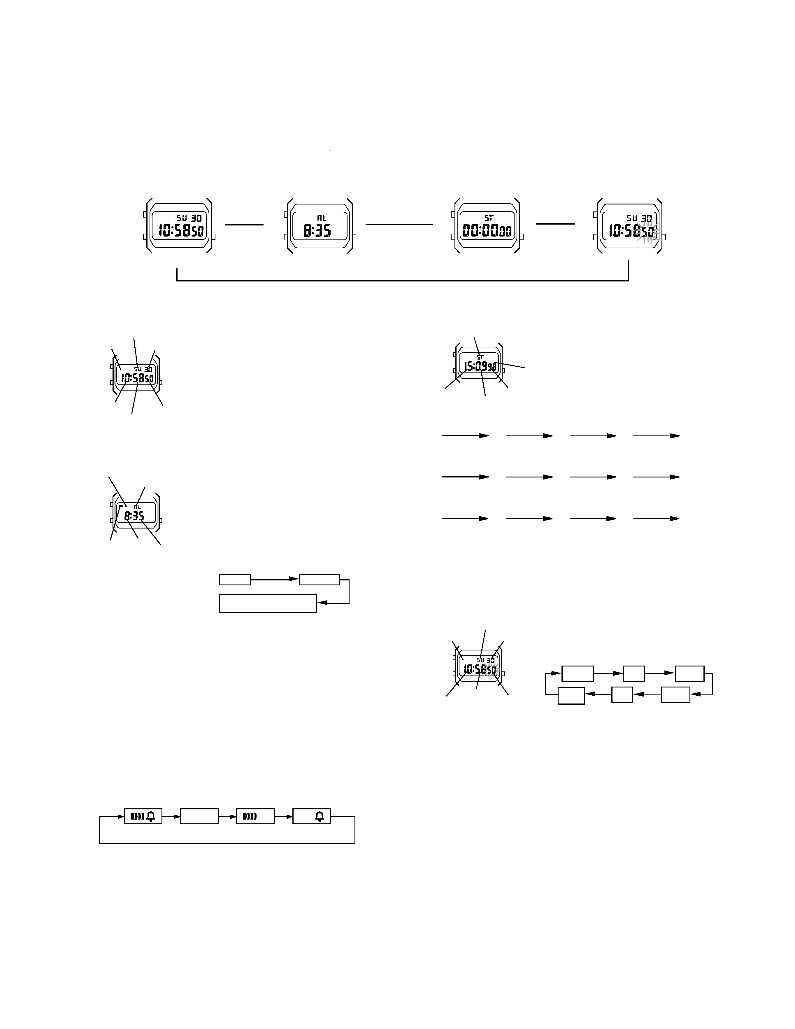
· Press B to change from mode to mode.
· After you perform an operation in any mode, pressing B returns to the Timekeeping Mode.
· Holding down A at any time illuminates the display.
· The backlight of this watch employs an electroluminescent (EL) light, which loses its illuminating power after very long term use.
· Frequent use of the backlight shortens the battery life.
OPERATION CHART:MODULE QW-1455
GENERAL GUIDE
PM
PM
v
v
v
v
Timekeeping Mode
Stopwatch Mode
Time Setting Mode
Timekeeping Mode
· In the Timekeeping Mode, press C to switch
between the 12-hour and 24-hour formats.
· Day of the week is displayed as follows.
SU:Sunday
MO:Monday
TU:Tuesday
WE:Wednesday
TH:Thursday
FR:Friday
SA:Saturday
PM
A
B
C
Date
Day of the week
PM indicator
Hour
Minute
Second
Alarm Mode
Hourly time signal on indicator
C
A
B
Mode indicator
Alarm on
indicator
Hour
Minutes
When the Daily Alarm is switched on, the alarm sounds
for 20 seconds at the preset time each day. When the
Hourly Time Signal is switched on, the watch beeps
every hour on the hour.
To set the alarm time
1. Hold down A while in the Alarm Mode until the hour
digits start to flash on the display. The hour digits
flash because they are
selected.
2. Press A to change the selection in the following
sequence.
Hour
Minutes
Normal Alarm Mode
(No digit flashes)
· Once you reach the normal Alarm Mode, you have to hold down A again until the hour
digits start to flash.
3. Press C to increase the selected digits. Holding down C changes the number at high
speed.
· The format (12-hour and 24-hour) of the alarm time matches the format you select for
normal timekeeping.
· When setting the alarm time using the 12-hour format, take care to set the time
correctly as morning or afternoon (PM).
4. After you set the alarm time, press A to return to the Alarm Mode. At this time the
Daily Alarm is switched on automatically.
To stop the alarm
Press A to stop the alarm after it starts to sound.
To switch the Daily Alarm and Hourly Time Signal on and off
Press C while in the Alarm Mode to change the status of the Daily Alarm and Hourly
Time Signal in the following sequence.
Stopwatch Mode
The Stopwatch Mode lets you measure elapsed time,
split times, and two finishes. The range of the stop-
watch is 59 minutes, 59.99 seconds.
Mode Indicator
SPLIT
A
B
C
Minutes
1/100 second
Split time indicator
Seconds
(a) Elapsed time measurement
CCCCA
Start
Stop
Re-start
Stop
Clear
Second runner
finishes.
Record time of
first runner.
Record time of
second runner.
First runner
finishes.
(b) Split time measurement
CAACA
Start
Split
Split release
Stop
Clear
(c) Split time and 1st-2nd place times
CACAA
Start
Split
Stop
Split release
Clear
Time Setting Mode
To set the time and date
1. Use B to enter the Time Setting Mode.
· The seconds digits flash because they are
selected.
2. Press A to change the selection in the following
sequence.
Day of the week
PM
A
BC
PM indicator
Date
Minutes
Hour
Seconds
Hour
Minutes
Seconds
Day of
Week
Date
Month
3. While the seconds digits are selected (flashing), press C to reset the seconds to "00". If
you press C while the seconds count is in the range of 30 to 59, the seconds are reset to
"00" and 1 is added to the minutes. If the seconds count is in the range of 00 to 29, the
minutes count is unchanged.
4. While any other digits (besides seconds) are selected (flashing), press C to increase the
number. While the day of the week is selected, pressing C advances to the next day.
Holding down C changes the current selection at high speed.
5. After you set the time and date, press B to return to the Timekeeping Mode.
· If you do not operate any button for a few minutes while a selection is flashing, the
flashing stops and the watch goes back to the Timekeeping Mode automatically.
Alarm Mode
[Alarm on Indicator/Hourly Time Signal on Indicator]
B
A
C
Hourly Time
Signal only
Daily Alarm
only
Both off
Both on
To test the alarm
Hold down C while in the Alarm Mode to sound the alarm.
-- 2 --
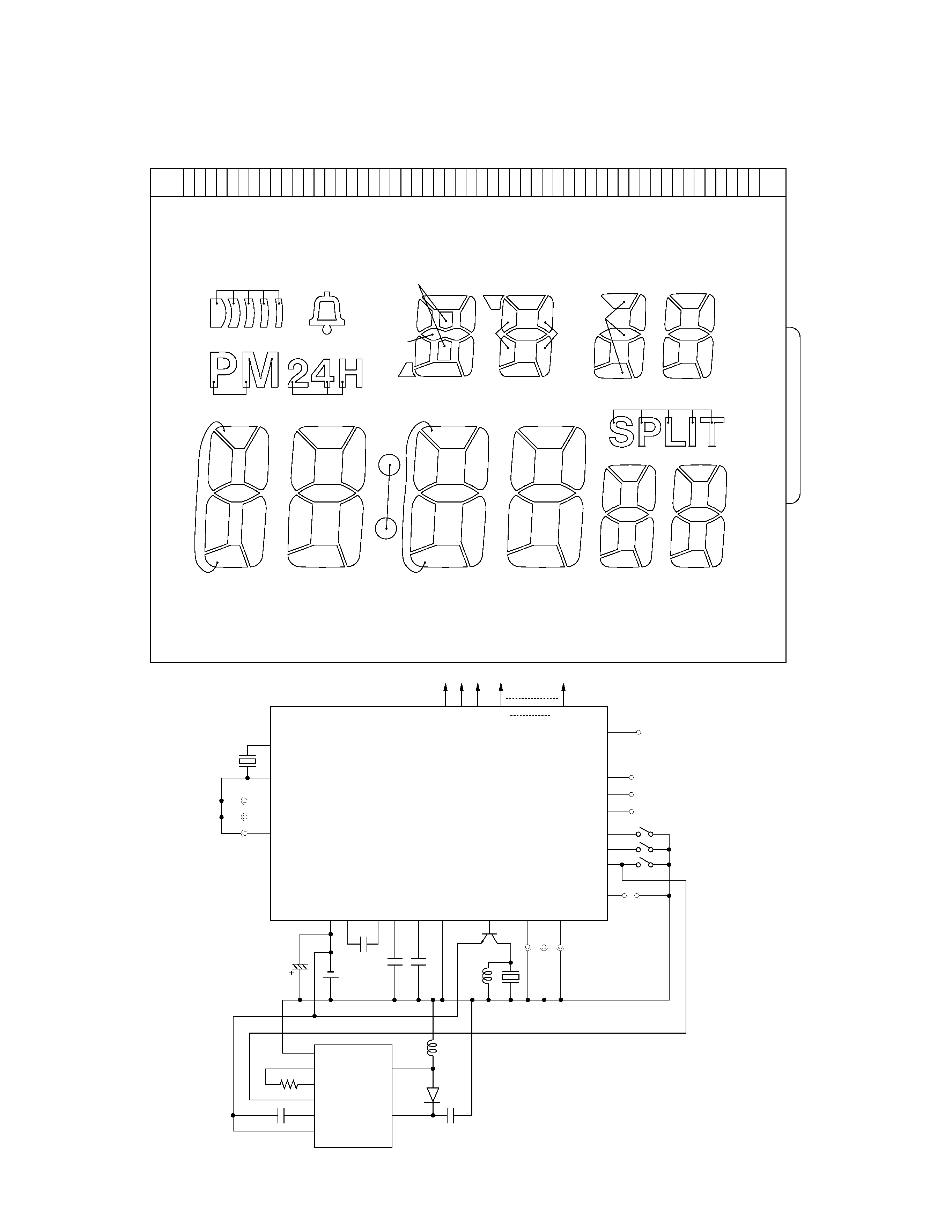
DRAWING AND SPECIFICATIONS: MODULE QW-1455
[BLOCK DIAGRAM]
L1
L2
L3
L4
L5
L6
LCX
LCY
LCZ
L7
L8
L9
L10
L11
L12
L13
L14
L15
L16
L17
L18
L19
L20
L21
L22
L23
L24
L7X
L8X
L10Y
L11X
L9Z
L10X
L11Y
L11Z
L10Z
L9X
L9Y
L12X
L13X
L12Z
L13Z
L12Y
L13Y
L15Y
L15X
L15Z
L14X
L17X
L16Y
L18Z
L16X
L17Y
L17Z
L16Z
L7Z
L8Z
L6Y
L5Y
L6Y
L6Z
L5Z
L5X
L6X
L4Z
L4Y
L3X
L7Y
L3Z
L3Y
L4X
L8Y
L2X
L1Y
L2X
L2Z
L1Z
L1X
L2Y
L23Z
L23Y
L24X
L24Z
L14Z
L23X
L24Y
L14Y
L22Z
L21Y
L21X
L22Y
L22X
L21Z
L20X
L20Z
L19Y
L18X
L20Y
L19Z
L18Y
L19X
LSI(CMOS)
TOTAL
BONDING
51PINS
50PINS
XTB
XT
CG1
CG2
CG3
Xtal
VBAT2
*1 T3
T1
T2
T4
S1
S3
S4
AC
S1
S3
S4
VBAT1
VCC
VC
VSS1
VSS2
VDD
BD
N1
N2
N3
LCX
LCY
LCZ
L1
L24
VCCE
RT2
RT1
ENB
VCPE
GND
CIL
ELD
INV
C1
C4
BAT
C2 C3
Tr
PZ
LL1
LL2
Di
EL
C5
R
-- 3 --
XT
XT
AC
S1
VDD
VDD
L
VDD
L
BD
VBAT1
RT2
RT1
S4
L
RT2
RT1
S4
VDD
VCPE
VCPE
CIL
VBAT1
ELD
CIL
VBAT1
VBAT1
CIL
VBAT1
ELD
VBAT1
ELD
CIL
VDD
VSS1
VDD
VSS2
VSS2
VDD
XT
XTB
VBAT1
S3
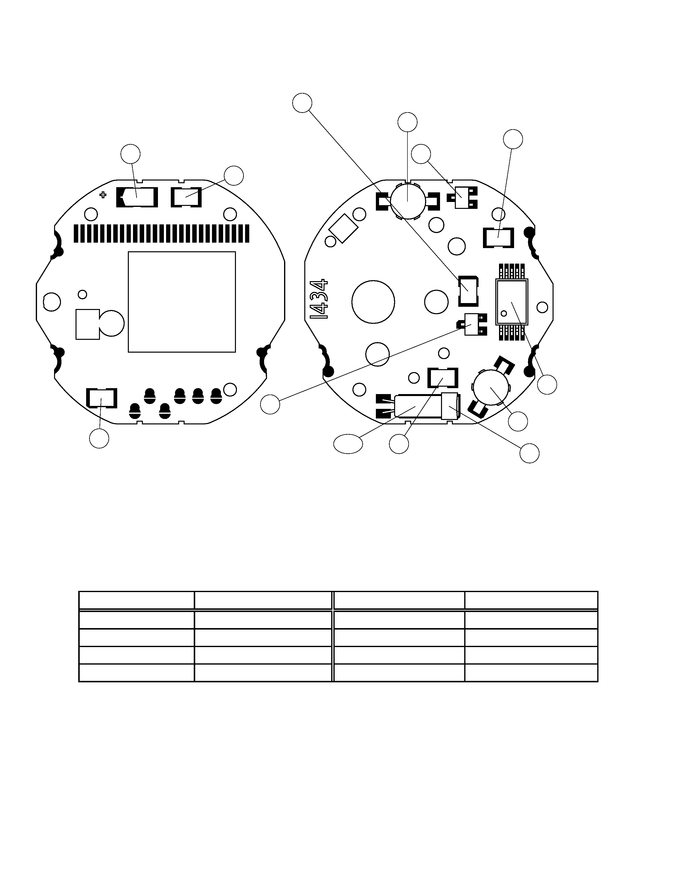
3. Transistor
(7110 1151)
Tr
5. Coil (for alarm)
(7020 0511)
LL1
11. Chip capacitor
(7103 7443)
C5
10. Chip capacitor
(7103 4446)
C3
12. Chip resistor
(2797 3129)
R
7. Inverter IC
(7100 7917)
INV
4. Diode
(7101 5609)
Di
6. Coil (for EL)
(7020 5413)
LL2
8. Quartz oscillator
(7110 0979)
Xtal
24. Cushion 6
(7211 0064)
S1
VBAT1
VC
VCC
VDD
XT
VDD
VDD
N1
N3
VDD
VDD
S4
ELD
S3
VDD
VSS1
N2
CG3
CG2
CG1
P.C.B. with
components
(7240 9039)
2.
C4
10. Chip capacitor
(7103 4446)
10. Chip capacitor
(7103 4446)
9. Tantalum capacitor
(2895 1358)
C1
C2
[ CHECKING TERMINALS AND COMPONENTS ]
[N1~N3, CG1~CG3 PADS]
Never solder or desolder these pads, because they have been selected best in the production line.
A new P.C.B. with components as a spare parts will be supplied with factory adjustment of these pads.
[SPECIFICATIONS]
Item
Detail
Item
Detail
Battery
CR1216
Accuracy
±30sec./month
Battery life
Approx. 2 years
Accuracy setting system
Pad selection (CG1~CG3)
Current consumption
1.20
µA maximum
Accuracy checking
See page 6
Alarm system
Piezo plate on Back cover
Accuracy setting
Unadjustable
Top view of P.C.B. ass'y
Bottom view of P.C.B. ass'y
-- 4 --
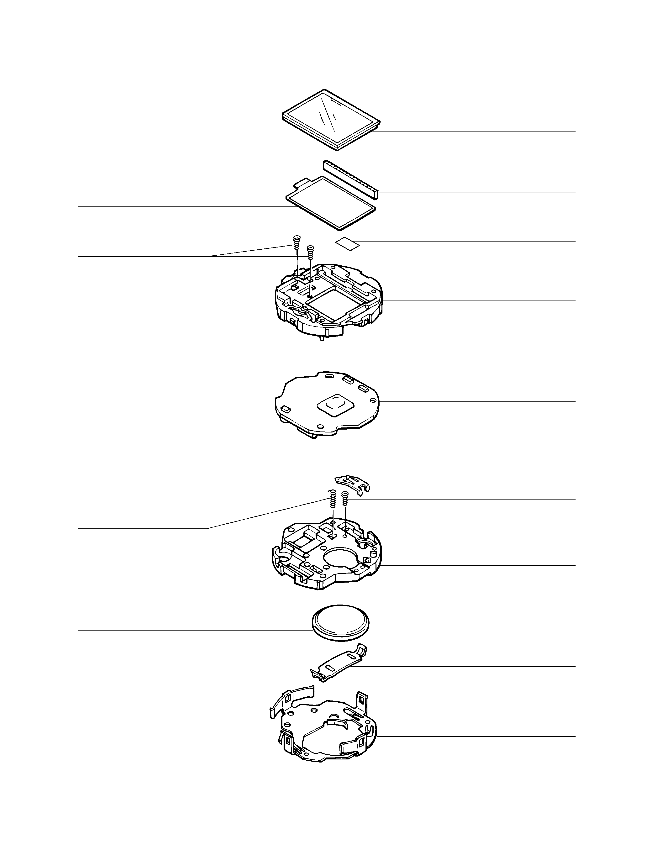
1 (7001 1974)
17 (7010 4420)
20 (7234 0819)
2 (7240 9039)
P.C.B with components
21 (7234 0826)
19 (7231 1414)
22 (7231 1372)
Battery (CR1216)
14 (7201 9687)
18 (7225 5105)
15 (7230 0616)
13a (7020 5721)
13b (7020 5735)
13c (7020 5742)
13d (7020 5756)
16 (7230 0917)
23 (7211 9631)
EXPLODED VIEW: MODULE QW-1455