R
QV-10A (C) (KX-723C)
APR. 1996
(without price)
(For PAL)

CONTENTS
SPECIFICATIONS ......................................................................................... 1
BLOCK DIAGRAM ........................................................................................ 2
CIRCUIT OPERATIONS ................................................................................ 3
COLOR ADJUSTMENT ............................................................................... 13
ADJUSTMENT ............................................................................................. 15
TROUBLESHOOTING ................................................................................. 18
DISASSEMBLY ........................................................................................... 19
ASSEMBLY ................................................................................................. 20
PRINTED CIRCUIT BOARDS ..................................................................... 21
EXPLODED VIEW ....................................................................................... 23
PARTS LIST ................................................................................................ 24
SCHEMATIC DIAGRAMS ........................................................................... 31
WAVEFORMS .............................................................................................. 34
-- 1 --
Item
Specification
1. Recording System
Digital (JPEG based)/Field recording
2. Video Signal System
PAL
3. Recording Medium
Built-in 16-Mbit flash memory
4. Number of pages
96
5. Delete Functions
Single page; All pages (with page protect feature)
6. Imaging Device
1/5-inch CCD (Total Number of Pixels: 250,000)
7. Lens
Fixed focus with macro position; F2/f = 5.2 mm
8. Aperture
F2.8/F8 manual switching
9. Focal Length
F2.8/NORMAL : 60 cm to 310 cm;
F2.8/MACRO
: 13 cm to 16 cm
F8/NORMAL
: 30 cm to
;
F8/MACRO
: 11 cm to 21 cm
(from lens protection filter)
10. Light Metering
TTL center point by photographic element
11. Exposure Metering
Aperture priority AE
12. Exposure Range
EV +5 to 18
13. Exposure Adjustment
-2 EV to +2 EV
14. Shutter System
Electronic
15. Shutter Speed
1/8 to 1/4000 second
16. White Balance
Automatic
17. Self-timer
10-second
18. Monitor
61,380-pixel 1.8-inch TFT low-glare color LCD
19. Terminals
DIGITAL; VIDEO OUT; DC IN 6 V
20. Power Supply
Batteries (AA-size Alkaline batteries
× 4)/AC Adaptor
21. Battery Life
Approximately 120 minutes (Playback mode)
22. Dimensions
66(H)
× 130(W) × 40(D)mm /
2.6" (H)
× 9" (W) × 1.6" (D)
23. Weight
Approximately 190 g / 6.7 oz (excluding batteries)
24. Accessories
Wirst strap; soft case; special video cable;
Alkaline batteries (LR6
× 4); cleaning cloth
SPECIFICATIONS
-- 2 --
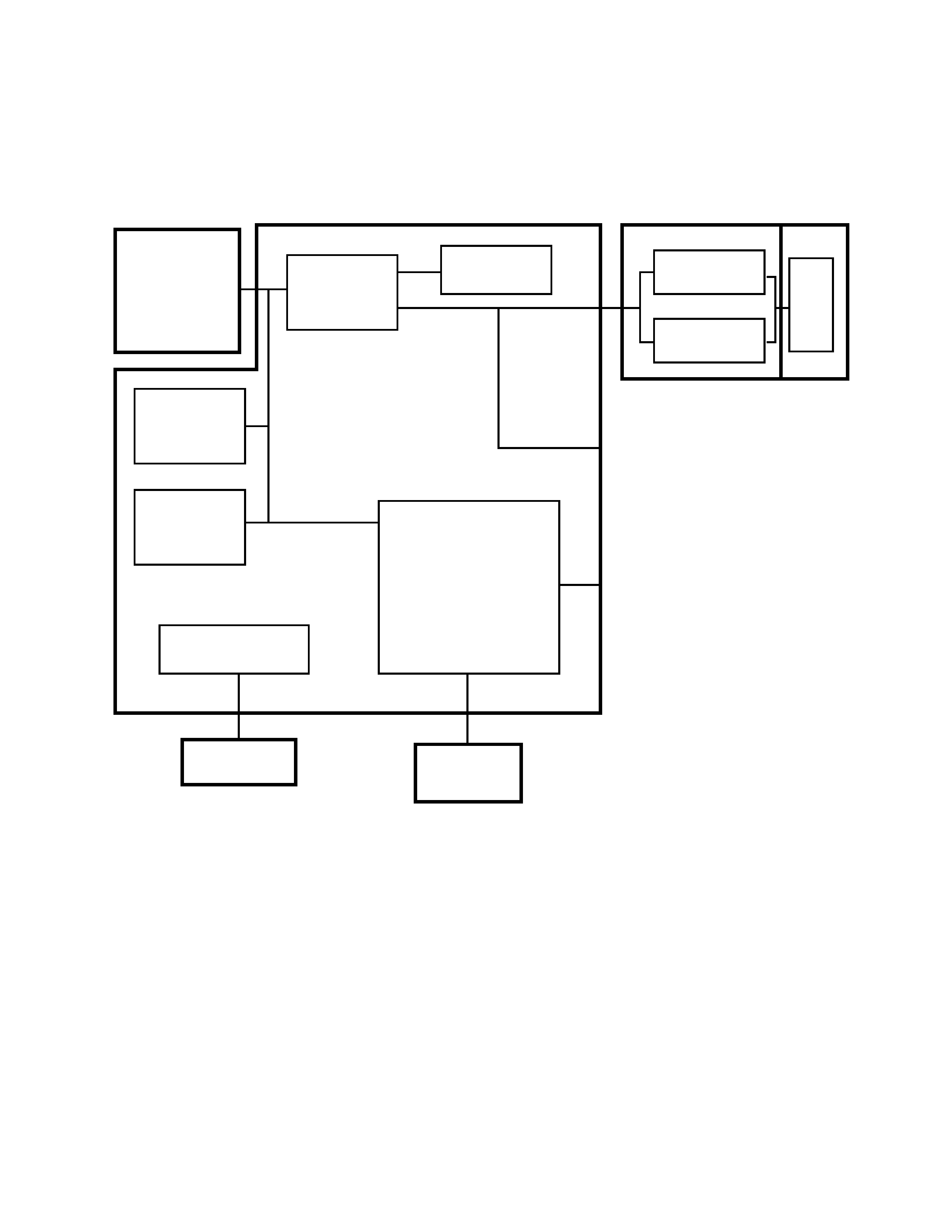
CCD
V RAM
HM53812BJ8
Gate Array
HG51B167FB
Flash
Memory
TC5816FT-1
D RAM
HM514B00
ALJ8
Power Supply
Circuit
DC IN (6V)
Key
CPU
HD6477034F16
Key PCB
AC adaptor
Battery x 4
IC400
MSM6770GS
IC300
IR3P90Y
LCD
3
3
3
3 Linear PCB
1 Camera Unit: It is used to provide color information.
2 Digital PCB: It controls the CCD, compressed data, stores image in memory.
3 Linear PCB: It generates the tricolor and controls the LCD display.
4 LCD: 61,380-pixel 1.8-inch Thin Film Transistor low-glare color LCD.
5 VIDEO OUT(Video I/O): Use this terminal when connecting to the VIDEO IN terminal of
a TV, video tape deck, video printer, or other similar device.
6 DIGITAL (SERIAL I/O): Use this terminal when connecting to a personal computer.
5
5
5
5 VIDEO OUT (Video I/O)
6
6
6
6 DIGITAL (Serial I/O)
1
1
1
1 Camera PCB 2
2
2
2 Digital PCB
BLOCK DIAGRAM
CPU
HD6437034F16
-- 3 --
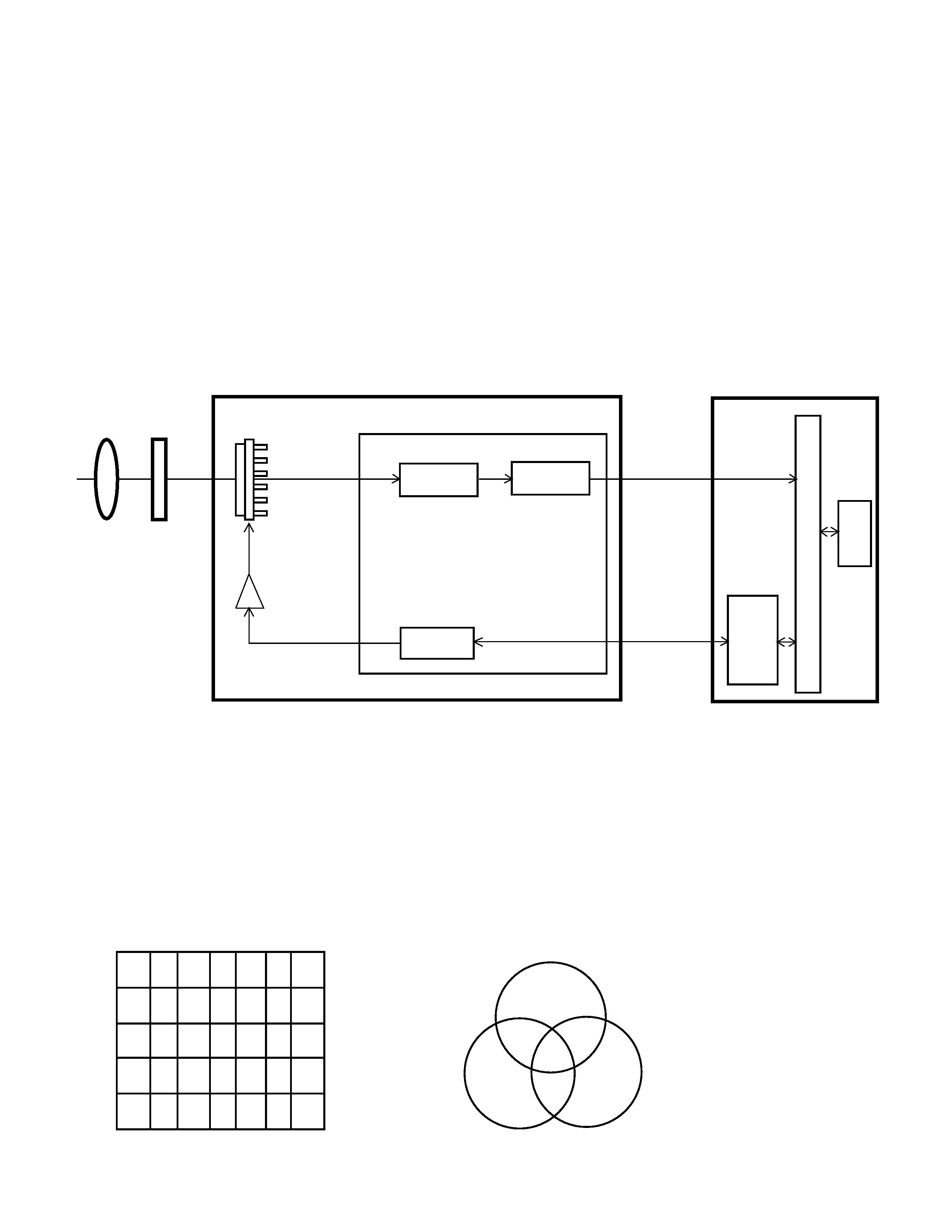
CAMERA UNIT (CAMERA PCB)
The camera unit is composed a lens, color filter, CCD (IC802), driver (IC800) and signal
processor (IC802). It produces voltages R, B, and G, for the colors red, blue, and green
when light from a scene is focused on the surface. These voltage values vary according
to the intensity of the respective color being scanned.
The camera unit must be replaced with whole unit when it is defective, because the precise
adjustment is required when the individual parts are replaced, and can be done only at our
factory.
2 Color
Filter
Ye,Cy,Gr
color signal
D0 ~ D7
IC800
Driver
VI1~ VI4
VS1 ~ VS4
PHI1~PHI4
PHS1~PHS4
MCK,
HRS2,
FTTRG,
STTRG,
CCODE,
ENDFLG
3 IC802 (CCD)
Sample Hold,
AGC
CCD IN
8bit A/D
Converter
Timing
Generator
4 IC801
CPU
Data Bus
D RAM
1 Lens
Concentrates light rays to a point.
2 Color filter
The striped color filter in front of the CCD detector is used to provide color information.
It has three colors, yellow, green and cyan.
Array of color filter and signal processing (IC801) for camera are extremely close relationship.
Ye G Cy
Ye G Cy
Ye G Cy
Ye G Cy
Ye G Cy
Ye G Cy
Ye G Cy
Ye G Cy
Ye G Cy
Ye G Cy
Array of color filter
Red
Blue
Green
White
Mg=Blue+Red
Ye=Red+Green
Cy=Blue+Green
Mg
Ye
Cy
Three Primary colors
1 Lens
Digital PCB
1
2
3
~ 506 507 508
Camera PCB
CIRCUIT OPERATIONS