JULY 1996
(without price)
QG-100(ZX-568)

CONTENTS
1. SPECIFICATIONS ..................................................................................................................... 1
2. CLEANING THE PRINTER ........................................................................................................ 1
3. BLOCK DIAGRAM .................................................................................................................... 2
4. SCHEMATIC DIAGRAMS
4-1. Wiring Diagram .................................................................................................................. 3
4-2. Main PCB Z568-1 (1/2) ....................................................................................................... 4
4-3. Main PCB Z568-1 (2/2) ....................................................................................................... 5
4-4. Power PCB Z568-S1 .......................................................................................................... 6
4-5. Sensor PCB Z568-2 ........................................................................................................... 7
4-6. Cam sensor PCB Z568-S2 ................................................................................................ 8
4-7. Paper, Ribbon & Jam sensor PCB Z568-S3 .................................................................... 8
4-8. Key Matrix Z568-E4 ........................................................................................................... 8
5. CIRCUIT EXPLANATION
5-1. LSI PIN FUNCTION ............................................................................................................ 9
5-2. CIRCUIT EXPLANATION ................................................................................................. 11
6. SETTING THE THERMAL HEAD ............................................................................................ 12
7. SENSOR POSITION, PRINTING SPECIFICATION & OPERATION CHECK ........................ 14
7-1. SENSOR POSITION ......................................................................................................... 15
7-2. PRINTING SPECIFICATION ............................................................................................. 15
7-3. OPERATION CHECK ....................................................................................................... 17
8. TROUBLE SHOOTING ............................................................................................................ 21
9. DISASSEMBLY ........................................................................................................................ 25
10. PARTS LIST
10-1. Z568-1 ASS'Y, COMPONENTS & OTHERS ................................................................... 27
10-2. PRINTER UNIT ............................................................................................................... 31
10-3. CHASSIS UNIT ............................................................................................................... 34
10-4. CHASSIS ASS'Y ............................................................................................................. 37
10-5. HEAD HOLDER ASS'Y .................................................................................................. 40
10-6. PLATEN ASS'Y .............................................................................................................. 43
10-7. CASSETTE CASE ASS'Y ............................................................................................... 45
10-8. MOTOR CHASSIS ASS'Y .............................................................................................. 47
11. EXPLODED VIEW & DISASSEMBLY VIEW
11-1. EXPLODED VIEW (Z568-1 ASS'Y & COMPONENTS) ................................................. 30
11-2. DISASSEMBLY VIEW (PRINTER UNIT) ........................................................................ 32
11-3. DISASSEMBLY VIEW (CHASSIS UNIT) ........................................................................ 35
11-4. DISASSEMBLY VIEW (CHASSIS ASS'Y) ...................................................................... 38
11-5. DISASSEMBLY VIEW (HEAD HOLDER ASS'Y) ............................................................ 41
11-6. DISASSEMBLY VIEW (PLATEN ASS'Y) ........................................................................ 44
11-7. DISASSEMBLY VIEW (CASSETTE CASE ASS'Y) ........................................................46
11-8. DISASSEMBLY VIEW (MOTOR CHASSIS ASS'Y) ........................................................48
-- 1 --
1. SPECIFICATIONS
Model:
QG-100
Print System:
Thermal transfer
Power Consumption:
20 W
Auto Power Off:
Approximately 30 minutes after last operation
Operating Temperature: 10
°C to 35 °C (50 °F ~ 95 °F)
Dimensions:
96.5 (H)
× 154 (W) × 154 (D) mm (313/16"H × 61/16 "W × 61/16"D)
Weight:
980 g (2.2 lbs)
Current:
DC 890 mA (TYP.), DC 1200 mA (MAX.) (printing)/DC 87 mA (TYP.),
DC 132 mA (MAX.) (power off)
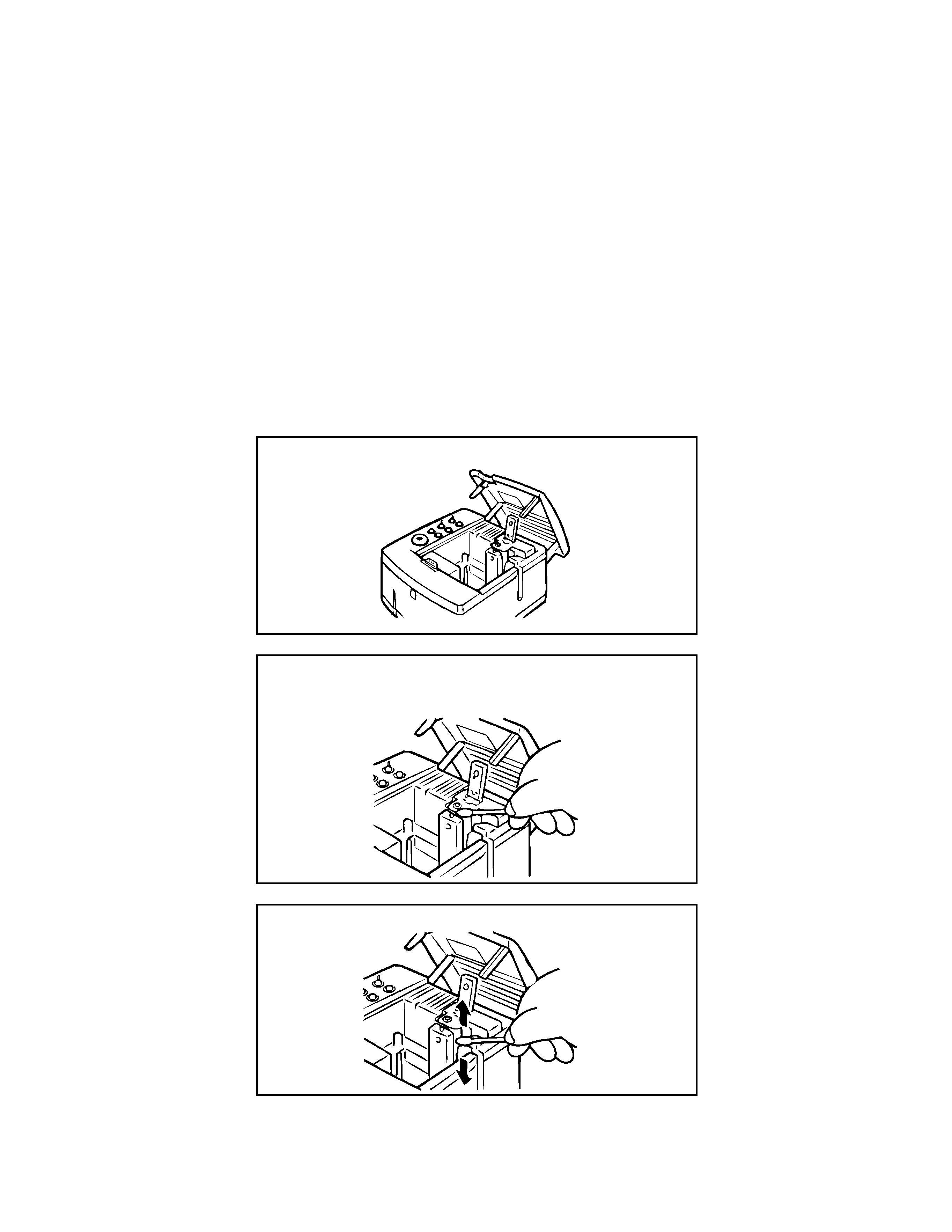
2. CLEANING THE PRINTER
For best printing results, use the following procedure to clean the print head and rollers with alcohol.
Also note that tape adhesive tends to accumulate on the sides of the tape outlet after long use of the
QG-100. When this happens, use an alcohol-moistened cotton swab to clean off the adhesive.
1 Open the printer's cover.
2 Use a thin cotton swab (the kind designed for infants)
moistened with alcohol to lightly wipe the printer head
as shown in the illustration.
3 Thoroughly wipe off the rubber rollers with the cotton
swab.
Important!
· The print head and other nearby metal parts become quite hot after the printer is used for a long time.
Make sure you allow these components to cool sufficiently before cleaning.
-- 2 --
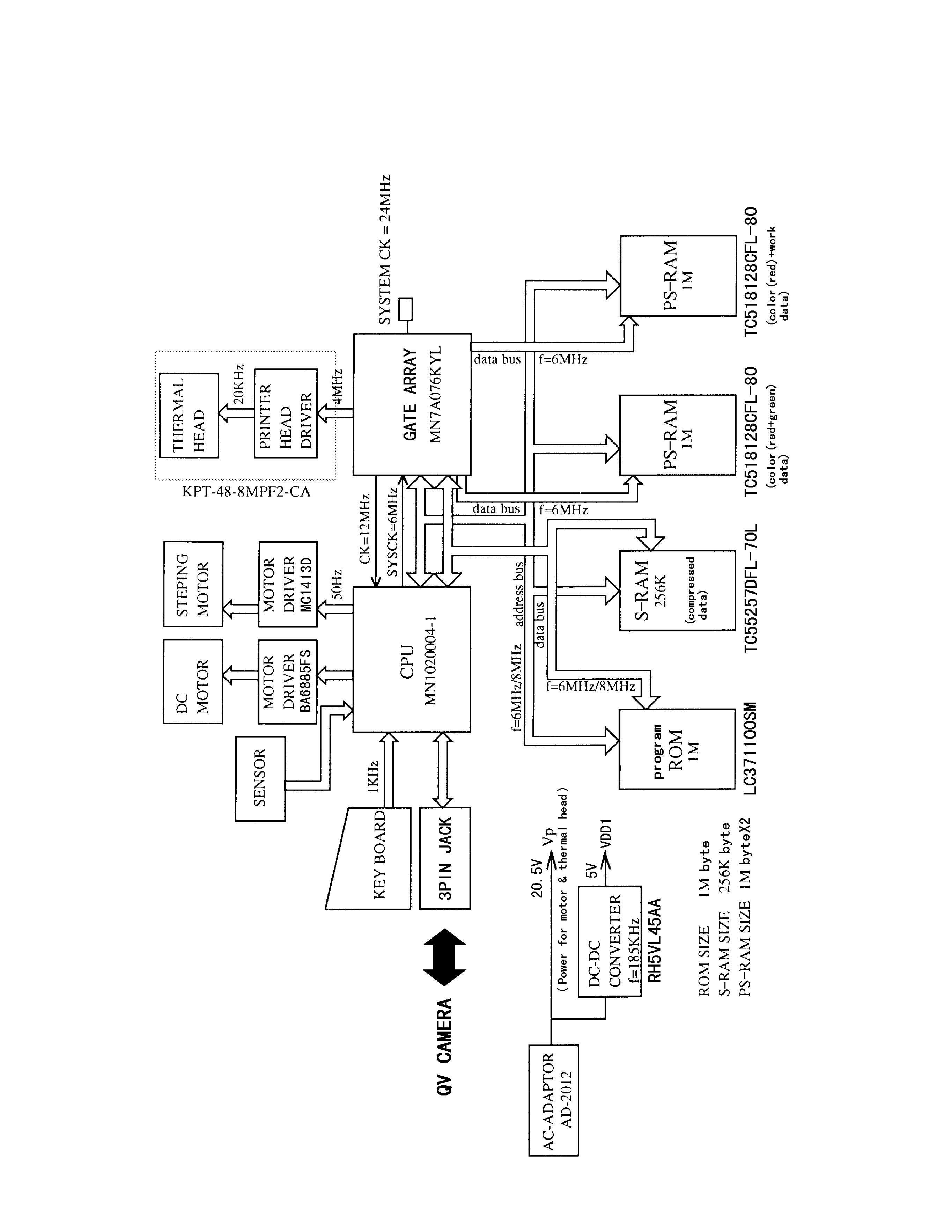
3. BLOCK DIAGRAM
-- 3 --
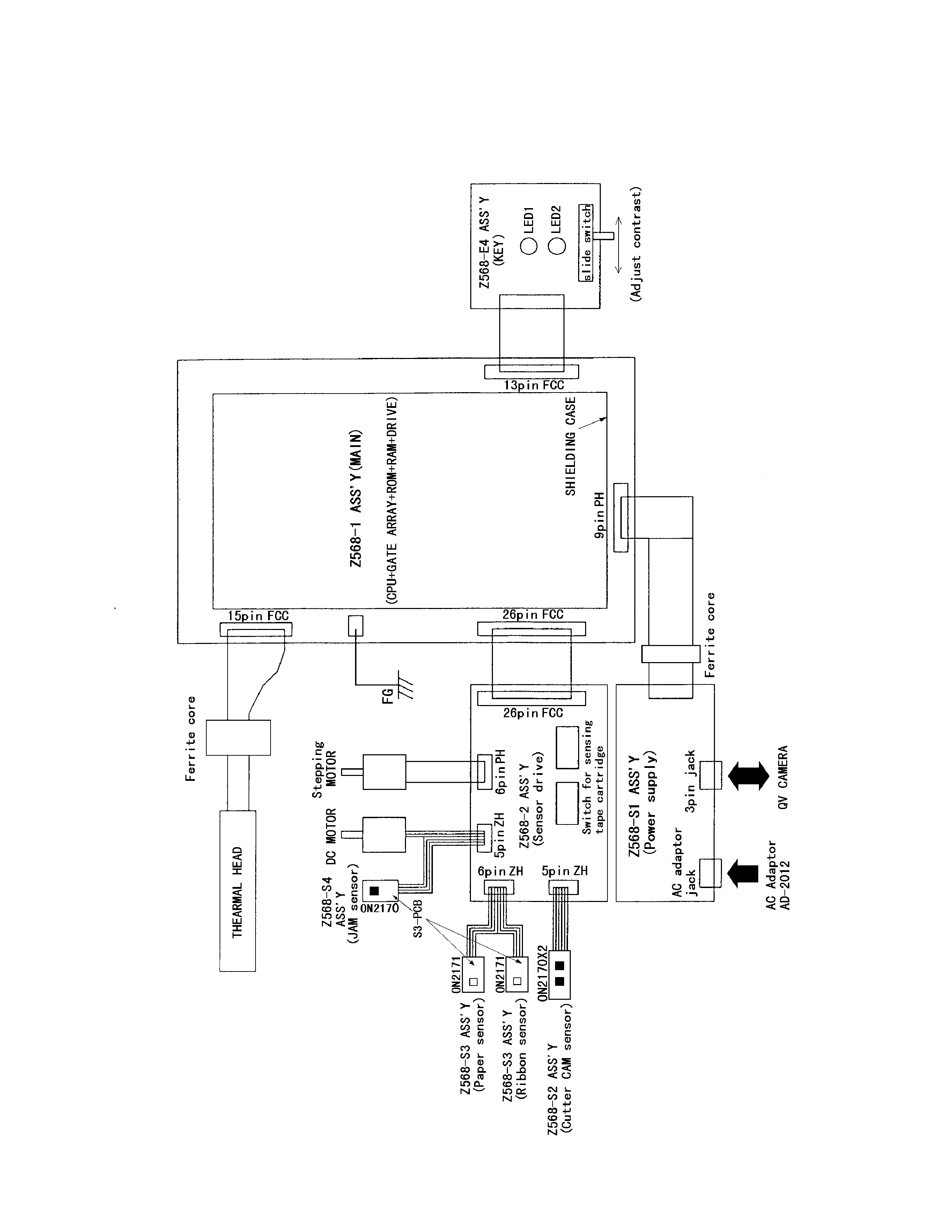
4. SCHEMATIC DIAGRAMS
4-1. Wiring Diagram