ELECTRIC GUITAR
EG-5
(without price)
INDEX

-- 2 --
CONTENTS
SPECIFICATIONS
GENERAL
Body:
Inner; Die cast aluminum
Outer; High impact PS resin
Neck:
Hard maple
Pickup:
CASIO original
Guitar controls:
Main Volume, Guitar Mix, Guitar Volume, Distortion ON/OFF, Distortion Drive
Tape recorder:
Recording system: Stereo
Playback system: Stereo (monaural speaker and monaural guitar output)
Tracks: 4-track, 2-channel stereo
Tape type: Normal
Tape speed: 4.76 cm/sec.
Fast forward/reverse time: approximately 150 sec. (C-60)
Recording level: Auto (automatically adjusted to prevent distortion)
Basic functions: REC, PLAY, F.FWD, STOP/EJECT, PAUSE
Other functions: Tape pitch adjustment (+/-3%), Auto stop
Built-In speaker:
10 cm dia. 2.0 W input rating: 1 pce.
Terminals:
Line In Jack [stereo mini jack, input impedance: 15 ohms]
Guitar Out Jack [monaural standard jack, output impedance: 4.5 ohms,
output voltage: 0.25 V (RMS) Maximum]
Phones Jack [Stereo mini jack, output impedance: 4.5 ohms,
output voltage: 0.50 V (RMS) Maximum]
AC Adaptor Jack (DC 9 V)
Power source:
DC: 6 AA size dry batteries
Battery life: Approx. two hours (R14P/SUM-2)
Approx. four hours (LR14/AM2)
AC: AC Adaptor AD-5
Power comsumption:
7.7 W
Dimensions (HWD):
75 x 966 x 324 mm
(2-15/16 x 38-1/16 x 12-3/4 inches)
Weight:
3.2 kg (7.0 lbs) including batteries
ELECTRICAL
Current drain with 9 V DC:
No Sound Output
92 mA
± 20%
Maximum volume
750 mA
± 20%
Speaker Output Level (Vrms with 8 ohms load)
with 6th string picked at 12th fret from 5th string
780 mA
± 30%
Phone Output Level (Vrms with 8 ohms load)
with 6th string picked at 12th fret from 5th string
65 mA
± 30%
Guitar Output Level (Vrms with 8 ohms load)
with 6th string picked at 12th fret from 5th string
32 mA
± 30%
Minimum Operating Voltage:
6.3 V
Specifications .................................................................................... 2
Block Diagrams ................................................................................. 3
Disassembly Instructions ................................................................ 5
Tuning ................................................................................................ 6
Adjustment ........................................................................................ 7
Circuit Description ............................................................................ 8
Wiring Diagram.................................................................................. 9
Schematic Diagrams ....................................................................... 10
Exploded View ................................................................................. 14
Parts List .......................................................................................... 15
--
3
--
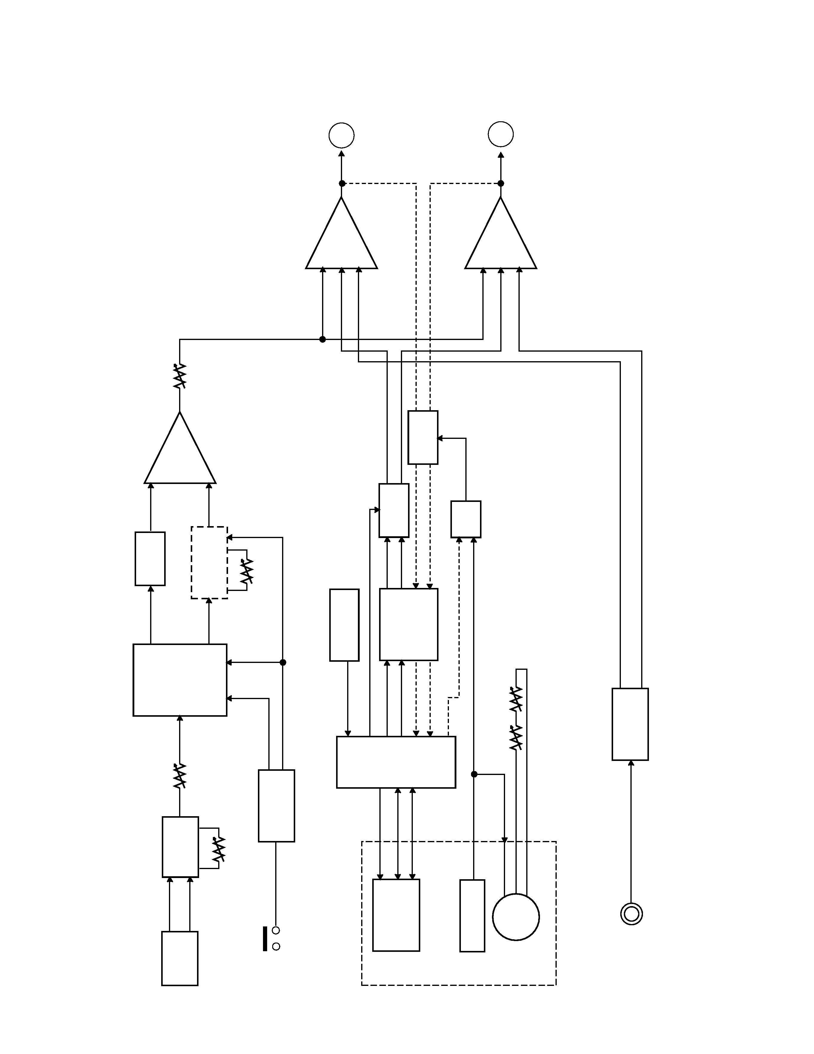
BLOCK
DIAGRAMS
Pickup
Hum
Cancel
VR11
Guitar Volume
Distortion
Changeover
T54, T55
Distortion
Circuit
Mixer
IC53
Guitar MIX
VR52
Distortion
Button
Flip-Flop
T51, T52
Head
Head Amp.
TA8142AP
IC41
Mute
T45, T46
Mute
T43, T44
Mixer R
IC42
Mixer L
IC42
Line IN
Line IN Amp.
HOT1
HOT2
Filter
Distortion Volume
VR51
Bias Circuit
Leaf Switch
Motor
Cassette Mechanism
REC
Switch
S41
VR31
VR32
Tape Speed Volume
SVC
MVC (Motor Drive Signal)
T42
T41, L41
BIAS
L-CH
R-CH
+
A
B
GUITAR-R
TAPE-R
AUX-R
GUITAR-L
TAPE-L
AUX-L
RAUX
LAUX
T21, T22
VR13
A
B
IC53
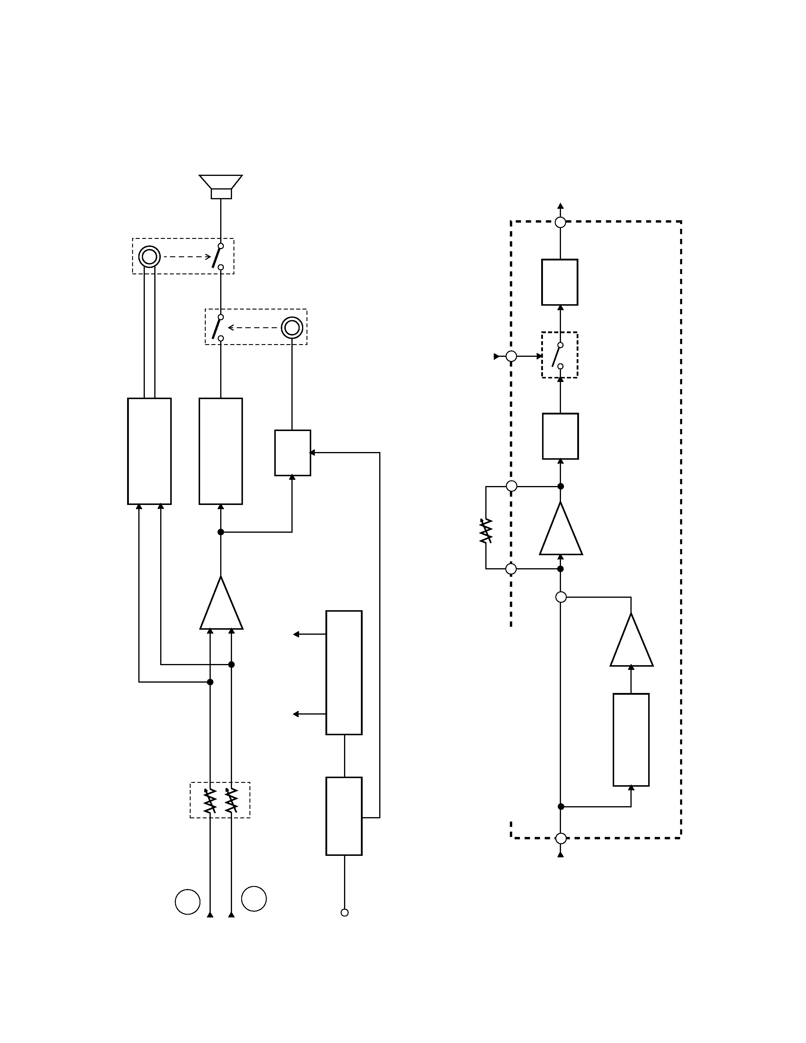
--
4
--
A
B
Main Volume
VR53
RVOUT
LVOUT
Mixer
Headphone Amp.
LA4525
IC21
Power Amp.
LA4127
IC13
Mute
T23
Phone Output
Guitar Output
Speaker
Power Supply Circuit
D22, T24
Power Switch
S21
VC 9 V
VCC 9 V
DC IN 9V
Amp.
Amp.
Clipper
Band-Pass Filter
IC51
VR51
Distortion Volume
DI505~DI508
IC51
IC52
T56
Filter
IC52
< DISTORTION CIRCUIT >
+
IC12
-- 5 --
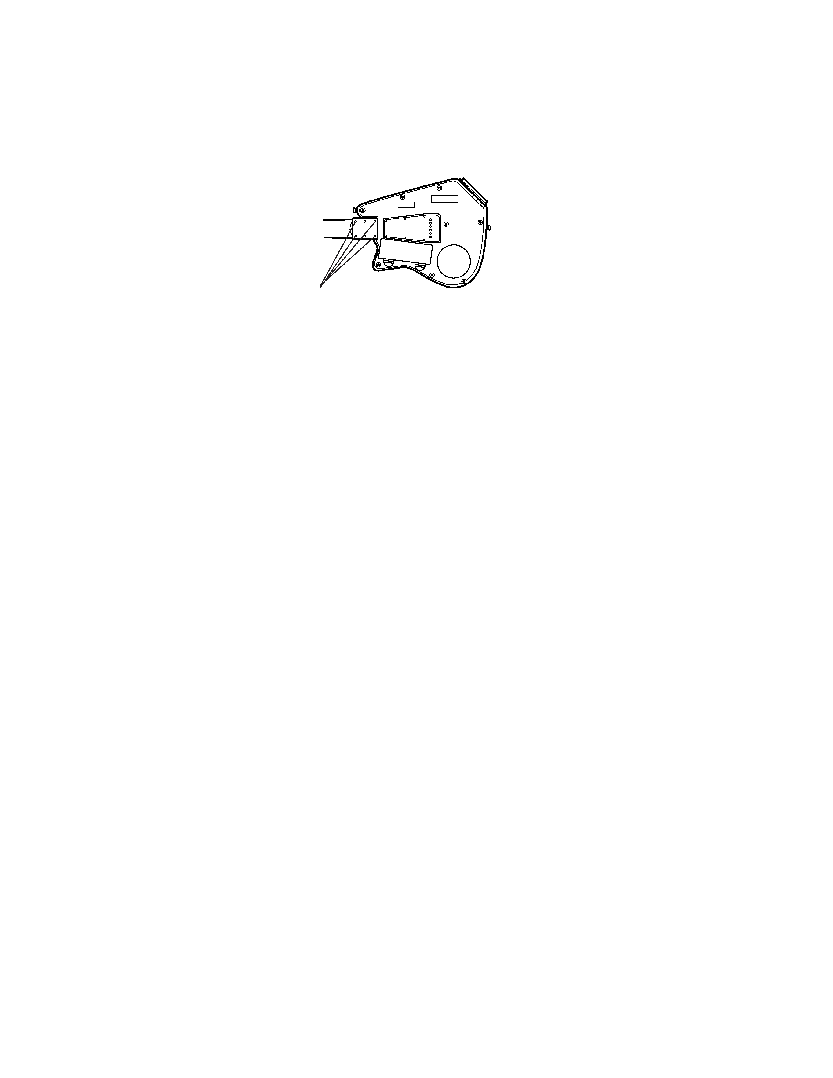
DISASSEMBLY INSTRUCTIONS
Note: EG-5 has a detachable neck. So do not loosen the four black screws attaching the neck to the body at
usual repairs. Only when replacing the neck, remove the screws.
Black Screws
< Figure 1 >
To open the lower body
1. Remove the battery cover.
2. Remove the eighteen screws holding the lower body.
3. Open the lower body.
To disassemble the cassette mechanism
1. Open the lower body.
2. Desolder PC cable, JD cable and PH cable on JCM370-MA4M PCB.
3. Remove three screws on JCM370-MA2M PCB and four screws on JCM370-MA4M PCB.
4. Remove all buttons from the cassette mechanism.
5. Remove the four screws holding the cassette mechanism.
6. Remove the cassette mechanism from the upper body.
To disassemble the pickup
1. Remove all strings from the guitar.
2. Open the lower body.
3. Desolder the cable of the pickup on JCM370-MA1M PCB.
4. Remove two black screws on the upper body.
To disassemble the bridge
1. Remove all strings from the guitar.
2. Remove four screws on the bridge.
To disassemble the neck
1. Remove all strings from the guitar.
2. Remove the four black screws on the lower body.