Zusätzlich erforder-
liche Unterlagen
für den
Komplettservice:
Additionally
required Service
Manuals for the
Complete Service:
Service
Manual
Ergänzung
Supplement
1
Sach-Nr./Part No.
72010-019.31
CUC 1825
CUC 1826
Sach-Nr./Part No.
72010-019.30
Service
Manual
Sicherheit
Safety
Sach-Nr./Part No.
72010-800.00
CUC 1826
CUC 1827
For these TV sets the Service Manual CUC 1825 / CUC 1826 is applicable.
This Manual describes the differences and the additionally fitted
modules of the TV receivers.
The individual modules and the relevant part numbers are listed in the
table on page 2.
Basic instructions for servicing are given in the:
Safety Instructions (Part No. 72010-800.00)
Service Manual CUC 1825 / CUC 1826 (Part No. 72010-019.30)
Für diese Geräte gilt das Service Manual CUC 1825 / CUC 1826.
Diese Ergänzung dokumentiert die Unterschiede bzw. zusätzlichen
Bestückungen der Geräte.
Die Bausteinbestückung und die Sachnummern der einzelnen Bau-
steine entnehmen Sie bitte der Tabelle auf Seite 2.
Grundlage für den Service sind:
Sicherheitsvorschriften (Sach-Nr. 72010-800.00)
Service Manual CUC 1825 / CUC 1826 (Sach-Nr. 72010-019.30)
GB
D
Inhaltsverzeichnis
Seite
Modulübersicht ................................................................................ 2
Technische Daten ........................................................................... 3
Platinenabbildungen Chassisplatte ................................................. 5
Gesamtschaltplan Netz-Chassis ................................................... 13
Gesamtschaltplan Color-Chassis .................................................. 17
Bedieneinheit 29501-082.48 ......................................................... 21
Bedieneinheit 29501-082.51 ......................................................... 22
Netzschalterplatte 29305-165.64 .................................................. 23
Netzschalterplatte 29305-165.65 .................................................. 24
Netzentstörplatte 29305-150.04 .................................................... 25
Fokussierungsplatte 29305-025.26 ............................................... 25
Bildrohrplatte 29305-122.10 .......................................................... 26
Ersatzteilliste ................................................................................. 28
Table of Contents
Page
Module List ...................................................................................... 2
Technical Data ................................................................................ 3
Layouts of Chassis Board ............................................................... 5
General Circuit Diagram Mains Chassis ....................................... 13
General Circuit Diagram Colour Chassis ...................................... 17
Control Unit 29501-082.48 ............................................................ 21
Control Unit 29501-082.51 ............................................................ 22
Mains Switch Panel 29305-165.64 ............................................... 23
Mains Switch Panel 29305-165.65 ............................................... 24
Mains Interference Elimination Board 29305-150.04 .................... 25
Focusing Board 29305-025.26 ...................................................... 25
CRT Panel 29305-122.10 ............................................................. 26
Spare Parts List ............................................................................ 28
SERVICE MANUAL
D
Btx *32700#
CUC 1826
M 63-281 IDTV / LOG
(9.21616-01 / G.CE 5481)
M 63-281/8 IDTV / LOG
(9.21616-02 / G.CE 6081)
M 70-281 IDTV / LOG
(9.21649-01 / G.CF 2881)
M 70-281/8 IDTV / LOG
(9.21649-02 / G.CF 8526)
ST 70-869 IDTV
(9.21612-02 / G.CF 0181)
Boston SE 7090 IDTV / LOG
(9.21650-01 / G.CF 3175)
(9.21650-01 / G.CF 3124)
Boston SE 7090 / 8 IDTV / LOG (9.21650-02 / G.CF 3275)
M 72-270 IDTV / LOG Elegance (9.21616-01 / G.CE 8526)
ST 72-261 IDTV / LOG
(9.21528-01 / G.CD 8869)
mit Toshiba-Bildröhre
ST 72-761/8 IDTV / LOG
(9.21528-02 / G.CD 8969)
mit Toshiba-Bildröhre
CUC 1827
M 84-210/8 IDTV / LOG
(9.21600-02 / G.CE 7290)
Änderungen vorbehalten
Printed in Germany
Service Manual Sach-Nr.
Subject to alteration
VK 24
1196
Service Manual Part No. 72010-019.31
Allgemeiner
Teil
/
General
Section
CUC
1826
/
1827
2
GRUNDIG
Service
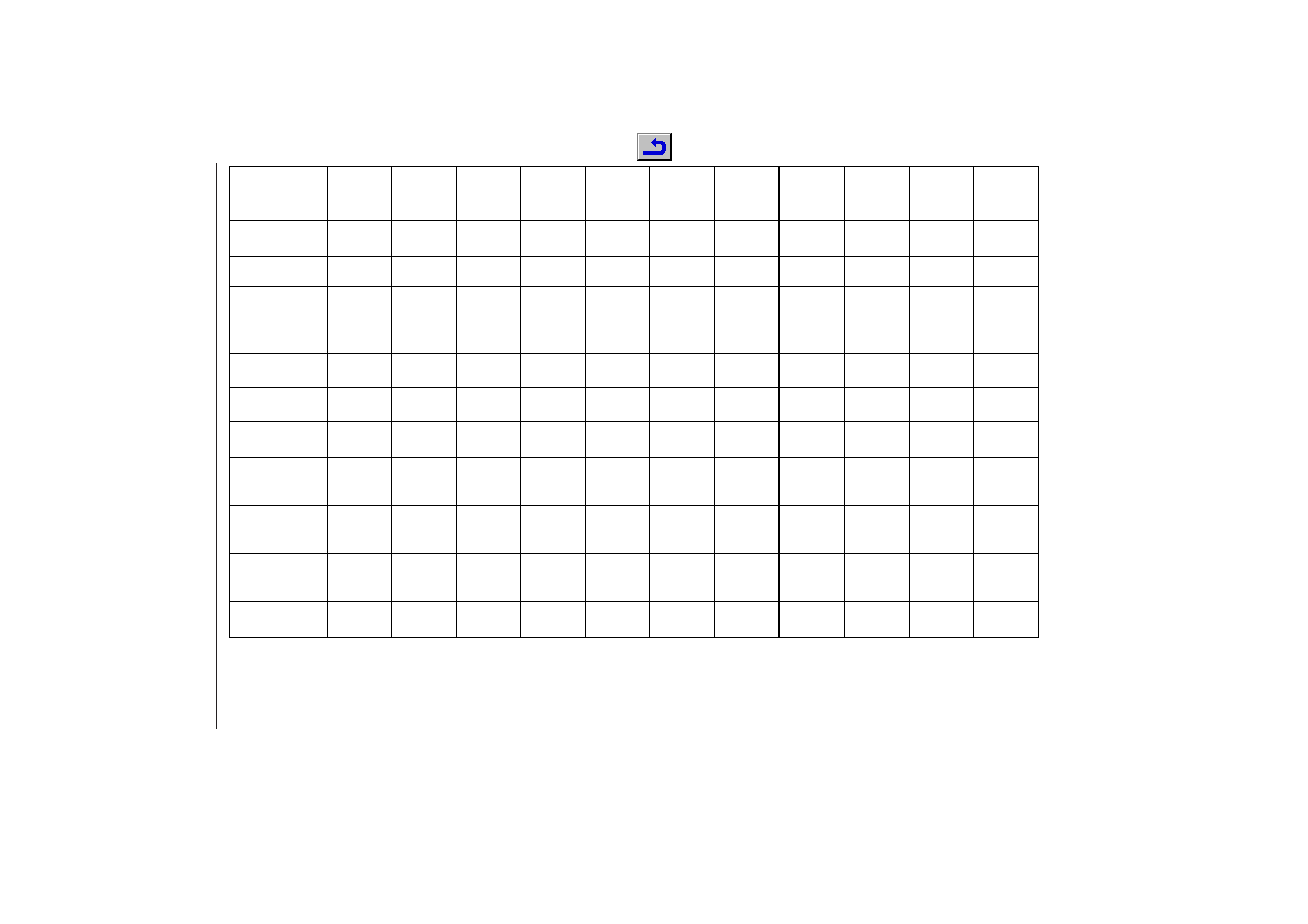
Modulübersicht
/
Module
List
M 63-281
IDTV / LOG
M 63-281/8
IDTV / LOG
M 70-281
IDTV / LOG
M 70-281/8
IDTV / LOG
ST 70-869
IDTV
Boston
SE 7090
IDTV / LOG
Boston
SE 7090/8
IDTV / LOG
M 72-270
IDTV / LOG
Elegance
ST 72-261
IDTV / LOG
ST 72-261/8
IDTV / LOG
M 84-210/8
IDTV / LOG
Chassis
29701-096.20
29701-096.21
29701-096.18
29701-096.19
29701-096.19
29701-096.18
29701-096.19
29701-096.11
29701-096.11
29701-096.16
29701-096.12
29701-096.17
29701-096.19
Tuner
29504-201.21
29504-201.21
29504-201.21
29504-201.21
29504-201.21
29504-201.21
29504-201.21
29504-201.21
29504-201.21
29504-201.21
29504-201.21
Signal-Baustein
Signal Module
29504-102.34
29504-162.34
29504-102.34
29504-162.34
29504-162.34
29504-102.34
29504-162.34
29504-102.34
29504-102.34
29504-162.34
29504-162.34
Bildrohrplatte
CRT Panel
29305-122.04
29305-122.04
29305-122.04
29305-122.04
29305-122.04
29305-122.04
29305-122.04
29305-122.10
29305-122.10
29305-122.12
29305-122.10
29305-122.12
29305-122.10
Bedieneinheit
Control Unit
29501-082.51
29501-082.51
29501-082.44
29501-082.44
29501-082.44
29501-082.37
29501-082.37
_
29501-082.43
29501-082.43
29501-082.48
Feature-Box
29504-103.37
29504-103.37
29504-103.37
29504-103.37
29504-103.37
29504-103.37
29504-103.37
29504-103.37
29504-103.37
29504-103.37
29504-103.37
Fernbedienung
Remote Control
29642-061.01
TP 800
29642-061.01
TP 800
29642-061.01
TP 800
29642-061.01
TP 800
29642-061.01
TP 800
29642-061.11
TP 900
29642-061.11
TP 900
29642-061.01
TP 800
29642-061.01
TP 800
29642-061.01
TP 800
29642-061.01
TP 800
Mövenent-
zerrungsplatte
N.S. Sea Gull Raster
Correction PCB
_______
29304-019.97
29304-019.97
29304-019.97
_
Netzschalterplatte
Mains Switch Panel
_______
29305-165.65
_
_
_
Netzentstörplatte
Mains Interference
Elimination Board
_______
29305-150.04
_
_
_
Fokussierungsplatte
Focusing Board
_______
_
29305-025.26
29305-025.26
_
CUC 1826 / 1827
Allgemeiner Teil / General Section
GRUNDIG Service
3
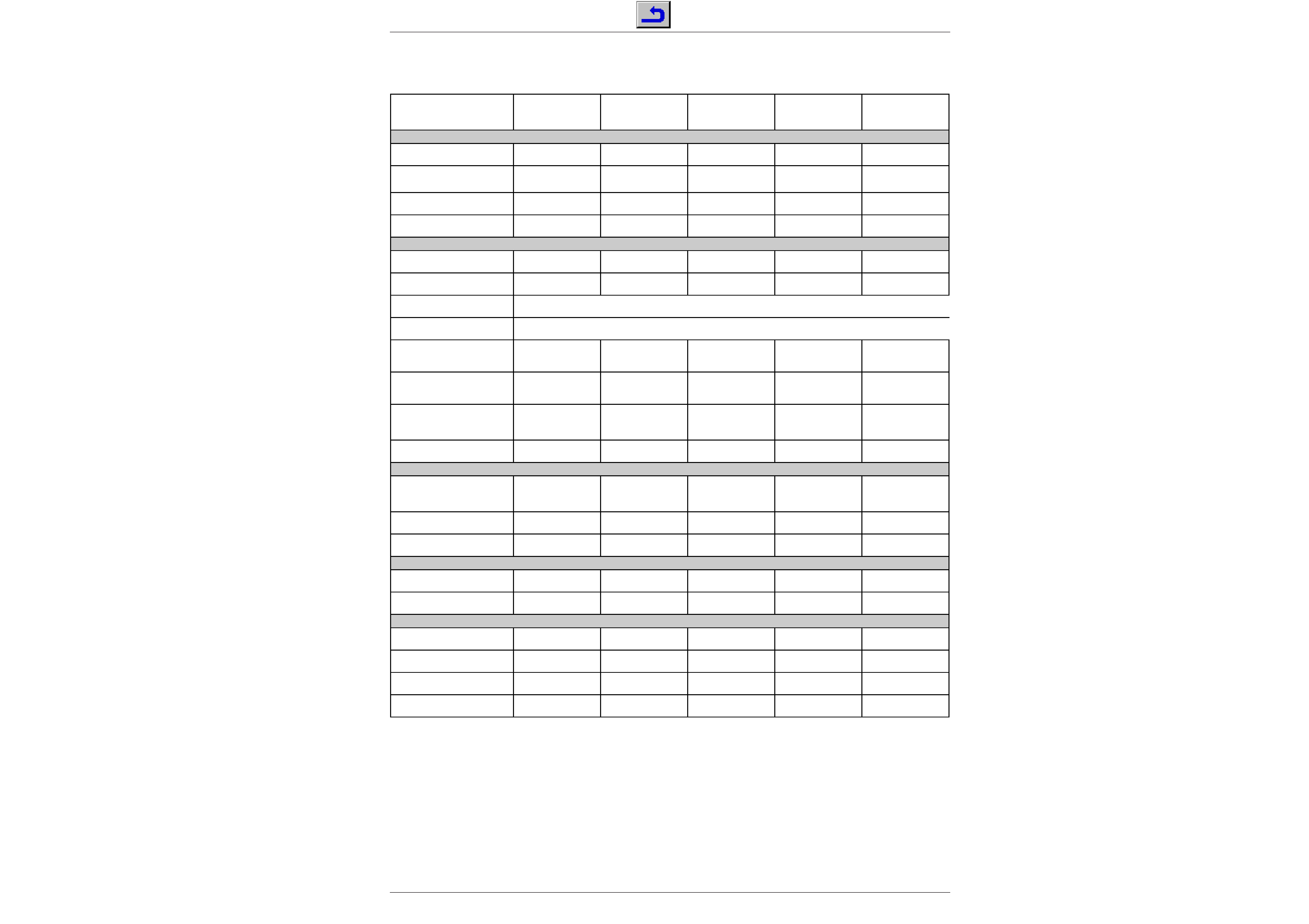
Technische Daten / Technical Data
M 63-281 IDTV/LOG
M 63-281/8 IDTV/LOG
M 70-281 IDTV/LOG
M 70-281/8 IDTV/LOG
ST 70-869 IDTV
Bildröhre / Picture Tube
Sichtbares Bild
Visible picture
59cm
59cm
66cm
66cm
66cm
Bildschirmdiagonale
Screen diagonale
63cm (25")
Black Line S, Black Matrix,
CCS, Invar
63cm (25")
Black Line S, Black Matrix,
CCS, Invar
70cm (28")
Black Line S, Black Matrix,
CCS, Invar
70cm (28")
Black Line S, Black Matrix,
CCS, Invar
70cm (28")
Megatron CCS
Ablenkwinkel
Deflection angle
110
°
110
°
110
°
110
°
110
°
Bildwechselfrequenz
Vertical frequency
100Hz
100Hz
100Hz
100Hz
100Hz
Elektronik / Electronic
Programmspeicherplätze
Programme positions
99 TV + 3 AV
99 TV + 3 AV
99 TV + 3 AV
99 TV + 3 AV
99 TV + 3 AV
Perfect clear, Blue stretch,
Gamma adjustment
ja / yes
ja / yes
ja / yes
ja / yes
ja / yes
AV-Auswertung
AV evaluation
auf jeden Programmplatz programmierbar / programmable for every programme position
Tuner
Kabeltuner-Raster 8MHz für Hyperband / cable tuner - 8MHz spacing for hyperband
TV-Normen
TV-Standard
PAL/SECAM/
NTSC 4,43MHz, B/G
PAL/SECAM/
NTSC 4,43MHz, B/G
PAL/SECAM/
NTSC 4,43MHz, B/G
PAL/SECAM/NTSC4,43MHz
,B/G, I, DK/K'/D, L/L',
input AV: NTSC 3,58 MHz
PAL/SECAM/NTSC4,43MHz
,B/G, I, DK/K'/D, L/L',
input AV: NTSC 3,58 MHz
Stereo Systeme
Stereo systems
Deutsch A2
German A2
Deutsch A2
German A2
Deutsch A2
German A2
Deutsch A2/German A2
Nicam 5,85+6,52
Deutsch A2/German A2
Nicam 5,85+6,52
Videotext
Teletext
8-Seiten TOP/FLOF Text
mit VPS
8-pages TOP/FLOF text
with VPS
8-Seiten TOP/FLOF Text
mit VPS
8-pages TOP/FLOF text
with VPS
8-Seiten TOP/FLOF Text
mit VPS
8-pages TOP/FLOF text
with VPS
8-Seiten TOP/FLOF Text
mit VPS
8-pages TOP/FLOF text
with VPS
8-Seiten TOP/FLOF Text
mit VPS
8-pages TOP/FLOF text
with VPS
Musikleistung
Music power
2x20W
2x20W
2x20W
2x20W
2x20W
Anschlüsse Front / Connections Front
Kopfhörer
Headphones
Stereo 3,5mm Klinken
Schaltbuchse /
Stereo 3.5mm jack switch
socket
Stereo 3,5mm Klinken
Schaltbuchse /
Stereo 3.5mm jack switch
socket
Stereo 3,5mm Klinken
Schaltbuchse /
Stereo 3.5mm jack switch
socket
Stereo 3,5mm Klinken
Schaltbuchse /
Stereo 3.5mm jack switch
socket
Stereo 3,5mm Klinken
Schaltbuchse /
Stereo 3.5mm jack switch
socket
Video IN
1 x Cinch
1 x Cinch
1 x Cinch
1 x Cinch
1 x Cinch
Audio IN
2 x Cinch
2 x Cinch
2 x Cinch
2 x Cinch
2 x Cinch
Anschlüsse Rückwand / Connections Rear Panel
Euro AV 1(schwarz/black)
FBAS in-/output, RGB input,
S-Video input, Megalogic
FBAS in-/output, RGB input,
S-Video input, Megalogic
FBAS in-/output, RGB input,
S-Video input, Megalogic
FBAS in-/output, RGB input,
S-Video input, Megalogic
FBAS in-/output, RGB input,
S-Video input, Megalogic
Euro AV 2 (orange)
FBAS in-/output, RGB input,
S-Video input
FBAS in-/output, RGB input,
S-Video input
FBAS in-/output, RGB input,
S-Video input
FBAS in-/output, RGB input,
S-Video input
FBAS in-/output, RGB input,
S-Video input
Netzteil / Mains Stage
Netzspannung (Regelbereich)
Mains voltage (variable)
165 ...264V
165 ...264V
165 ...264V
165 ...264V
165 ...264V
Netzfrequenz
Mains frequency
50 / 60Hz
50 / 60Hz
50 / 60Hz
50 / 60Hz
50 / 60Hz
Leistungsaufnahme
Power consumption
ca. 120W
ca. 120W
ca. 140W
ca. 140W
ca. 140W
Standby
ca. 7W
ca. 7W
ca. 7W
ca. 7W
ca. 7W
Allgemeiner Teil / General Section
CUC 1826 / 1827
4
GRUNDIG Service
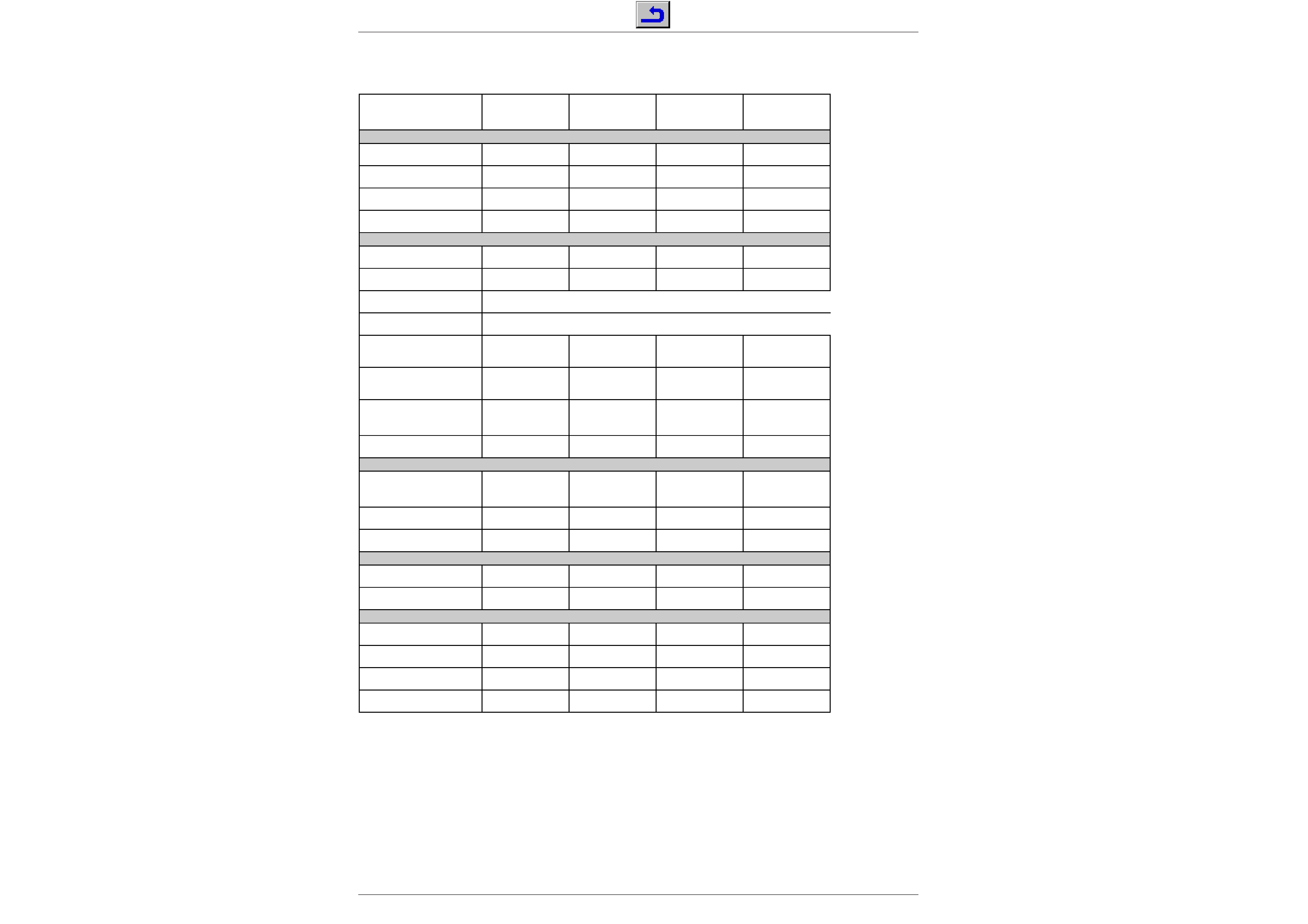
Technische Daten / Technical Data
Boston SE 7090
IDTV/LOG
Boston SE 7090/8
IDTV/LOG
M 72-270
IDTV/LOG
Elegance
M 84-210/8
IDTV/LOG
Bildröhre / Picture Tube
Sichtbares Bild
Visible picture
66cm
66cm
68cm
80cm
Bildschirmdiagonale
Screen diagonale
70cm (28"), Megatron
Black Matrix, CCS
70cm (28"), Megatron
Black Matrix, CCS
72cm (29"), Megatron,
Black Line S, Invar, CCS
84cm (33"), Megatron
Black Line S, Invar, CCS
Ablenkwinkel
Deflection angle
110
°
110
°
110
°
110
°
Bildwechselfrequenz
Vertical frequency
100Hz
100Hz
100Hz
100Hz
Elektronik / Electronic
Programmspeicherplätze
Programme positions
99 TV + 3 AV
99 TV + 3 AV
99 TV + 3 AV
99 TV + 3 AV
Perfect clear, Blue stretch,
Gamma adjustment
ja / yes
ja / yes
ja / yes
ja / yes
AV-Auswertung
AV evaluation
auf jeden Programmplatz programmierbar / programmable for every programme position
Tuner
Kabeltuner-Raster 8MHz für Hyperband / cable tuner - 8MHz spacing for hyperband
TV-Normen
TV-Standard
PAL/SECAM/
NTSC 4,43MHz, B/G
PAL/SECAM/NTSC4,43MHz
,B/G, I, DK/K'/D, L/L',
in AV: NTSC 3,58 MHz
PAL/SECAM/
NTSC 4,43MHz, B/G
PAL/SECAM/NTSC4,43MHz
,B/G, I, DK/K'/D, L/L',
in AV: NTSC 3,58 MHz
Stereo Systeme
Stereo systems
Deutsch A2/German A2
Nicam 5,85+6,52
Deutsch A2
German A2
Deutsch A2/German A2
Nicam 5,85+6,52
Videotext
Teletext
8-Seiten TOP/FLOF Text
mit VPS
8-pages TOP/FLOF text
with VPS
8-Seiten TOP/FLOF Text
mit VPS
8-pages TOP/FLOF text
with VPS
8-Seiten TOP/FLOF Text
mit VPS
8-pages TOP/FLOF text
with VPS
8-Seiten TOP/FLOF Text
mit VPS
8-pages TOP/FLOF text
with VPS
Musikleistung
Music power
2x20W
2x20W
2x20W
2x20W
Anschlüsse Front / Connections Front
Kopfhörer
Headphones
Stereo 3,5mm Klinken
Schaltbuchse /
Stereo 3.5mm jack switch
socket
Stereo 3,5mm Klinken
Schaltbuchse /
Stereo 3.5mm jack switch
socket
Stereo 3,5mm Klinken
Schaltbuchse /
Stereo 3.5mm jack switch
socket
Stereo 3,5mm Klinken
Schaltbuchse /
Stereo 3.5mm jack switch
socket
Video IN
1 x Cinch
1 x Cinch
1 x Cinch
1 x Cinch
Audio IN
2 x Cinch
2 x Cinch
2 x Cinch
2 x Cinch
Anschlüsse Rückwand / Connections Rear Panel
Euro AV 1(schwarz/black)
FBAS in-/output, RGB input,
S-Video input, Megalogic
FBAS in-/output, RGB input,
S-Video input, Megalogic
FBAS in-/output, RGB input,
S-Video input, Megalogic
FBAS in-/output, RGB input,
S-Video input, Megalogic
Euro AV 2 (orange)
FBAS in-/output, RGB input,
S-Video input
FBAS in-/output, RGB input,
S-Video input
FBAS in-/output, RGB input,
S-Video input
FBAS in-/output, RGB input,
S-Video input
Netzteil / Mains Stage
Netzspannung (Regelbereich)
Mains voltage (variable)
190 ...264V
190 ...264V
165 ...264V
190 ...264V
Netzfrequenz
Mains frequency
50 / 60Hz
50 / 60Hz
50 / 60Hz
50 / 60Hz
Leistungsaufnahme
Power consumption
ca. 140W
ca. 140W
ca. 135W
ca. 155W
Standby
ca. 7W
ca. 7W
ca. 6W
ca. 7W
/2L(06)
12
.
0
1
2
3
4
5
6
7
8
9
29304-730.11
20
21
22
19
12
9
10
8
11
3
1
4
5
2
6
7
56
48
47
65
64
66
70
68
69
67
49
C
25
L´
27
18
14
15
54
44
63
62
33
53
61
60
59
58
32
36
38
39
37
41
42
43
45
46
13
34
24
35
26
23
52
16
17
51
52
57 55
30
40
29
50
31
28
GRUNDIG Service
5
GRUNDIG Service
CUC 1826 / 1827
CUC 1826 / 1827
Schaltpläne und Druckplattenabbildungen / Circuit Diagrams and Layout of PCBs
Schaltpläne und Druckplattenabbildungen / Circuit Diagrams and Layout of PCBs
6
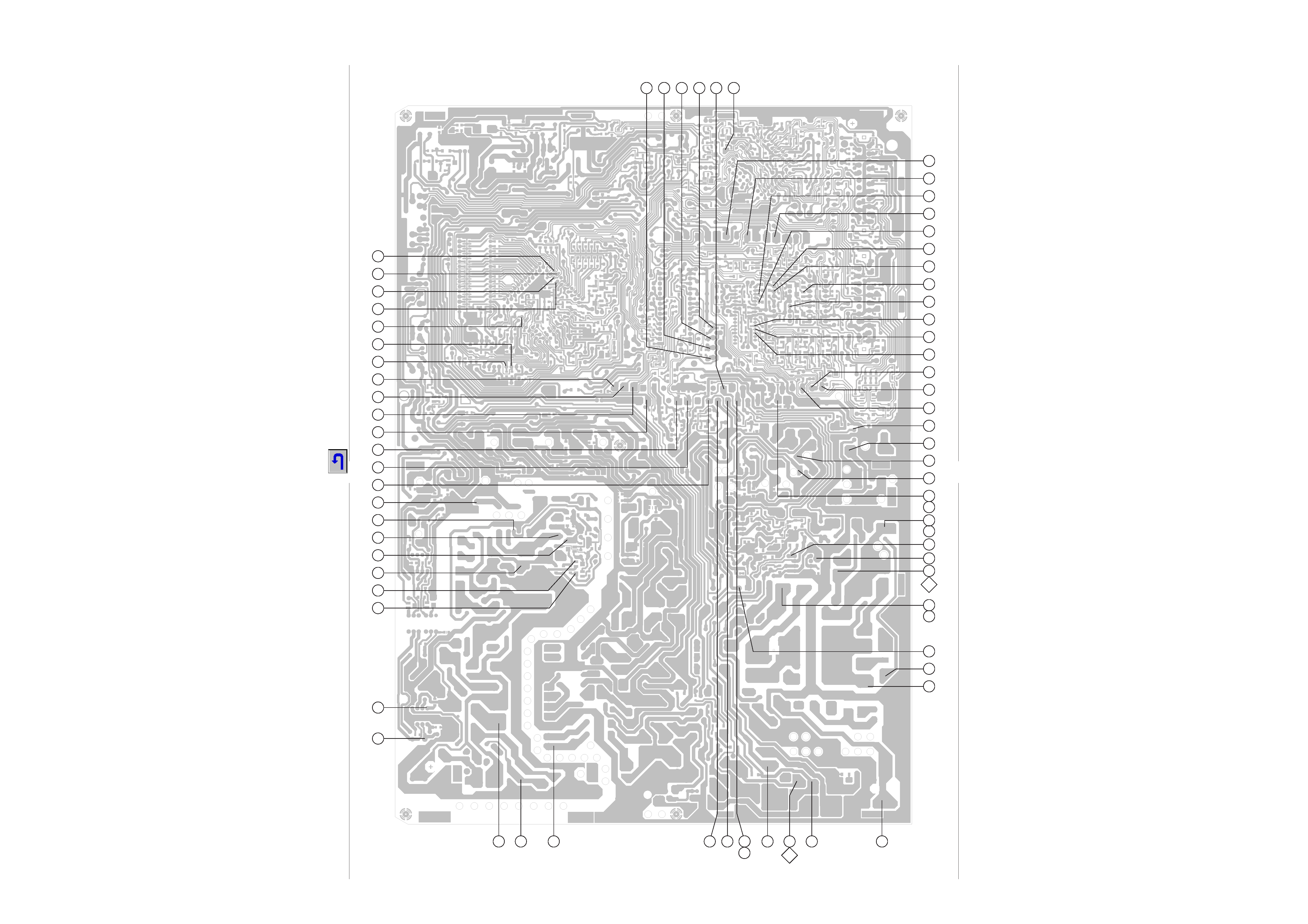
Oszillogramm-Meßpunkte Chassisplatte / Oscillogram Test Points Chassis Board
Lötseite, Ansicht von unten
Solder side, bottom view