Service Manual for
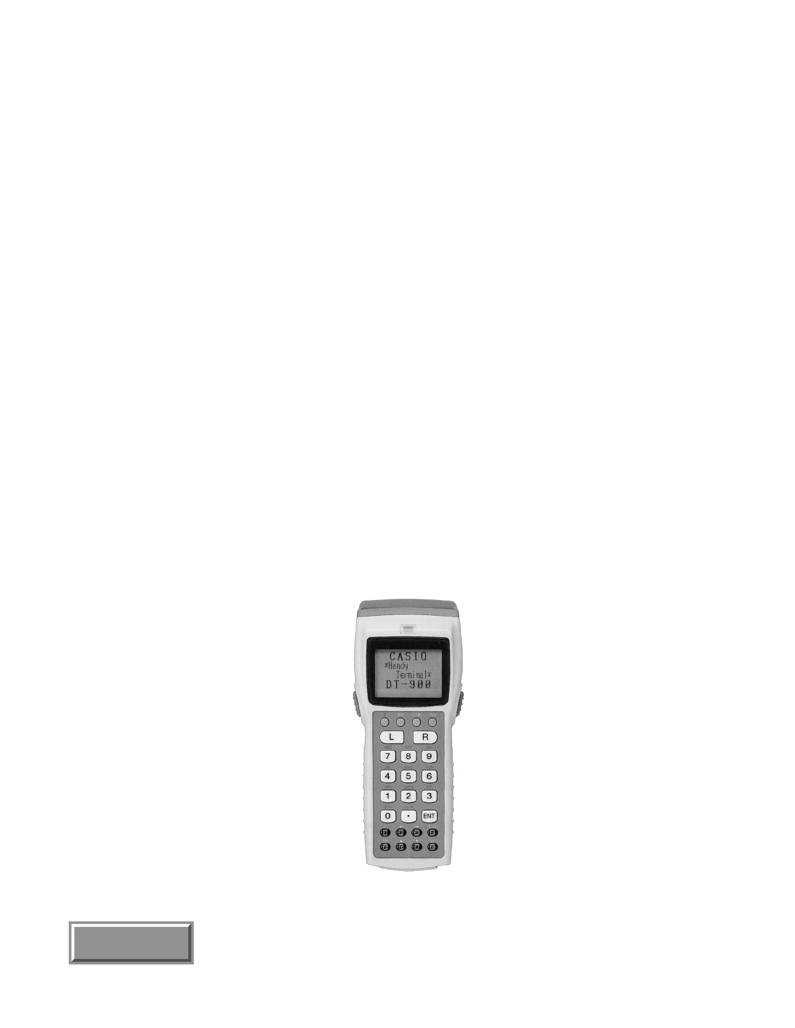
DT-900
(PX-710)
Date: December 1998
DT-900
INDEX
REVISE DATE : FEB-99
REVISE DATE : AUG.00

CONTENTS
page
1. SPECIFICATIONS ...................................................................... 1
2. SYSTEM STRUCTURES ........................................................... 4
3. BLOCK DIAGRAMS .................................................................. 7
4. DISASSEMBLY/ASSEMBLY .................................................... 9
5. POWER SUPPLY ...................................................................... 15
6. SYSTEM FILE LOADING
(OS/KCG/DIAGNOSTIC PROGRAM) .................................. 19
7. BAR CODE CALIBRATION SETTING ................................ 25
8. DIAGNOSTIC PROGRAM ...................................................... 29
9. TROUBLESHOOTING ............................................................ 47
10. CIRCUIT DIAGRAM ............................................................... 50
11. PRATS LIST .............................................................................. 66
Page 1
1. SPECIFICATIONS
Device
Clock frequency
Capacity
Access time
Capacity
Access time
Device
Clock frequency
Function
Clock
Alarm
Accuracy
Volume
LCD panel
Fonts
No. of
Display
fonts
Graphic-RAM
Contrast adjustment
Backlight
INIT key
HD6437020SU01X (32bit RISC)
4.92/2.46/1.23MHz
16Mbit
70ns
16Mbit
90ns
SLA407AF0S
14.7456MHz/32.768kHz
Bus control (BCU)
Memory management (MMU)
Calendar, clock (RTC)
Serial interface (SIF)
Power management(PMU)
Laser interface (LCU)
Timer (GAITU)
Key interface (KBC)
Display interface (LCDC)
Year/Month/Day/Hour/Minute
Second/A day of the week/Leap year
Hour/Minute
± 60seconds/Month (Max)
4steps (Large/Middle/Small/Off)
75 dB at 30 cm
STN LCD
128
× 64 dots
0.30
× 0.35 mm
ANK, Kanji (JIS levels 1st, 2nd, User-
defined fonts
× 128)
21 digits
× 10 lines
16 digits
× 8 lines
12 digits
× 6 lines
10 digits
× 5 lines
20 digits
× 5 lines
8 digits
× 4 lines
16 digits
× 4 lines
6 digits
× 3 lines
12 digits
× 3 lines
1KByte (Internal in the LCDD)
16steps/Controlled by electric volume
EL
Rubber contact
Push key
CPU and Peripherals
Clock/Calendar
Buzzer
Display
Input device
6 dot FONT
6
× 6
8 dot FONT
8
× 8
10 dot FONT 10
× 10
12 dot FONT 12
× 12
12 dot FONT
6
× 12
16 dot FONT 16
× 16
16 dot FONT
8
× 16
20 dot FONT 20
× 20
20 dot FONT 10
× 20
Block
Item
Specification
Step
Max. level
Type
Number of dots
Dot pitch
Type
Type
CPU
RAM
F-ROM
Gate Array
ON key/Numeric key/
Function key/L,R key/
Trigger key
Page 2
Method
Wave length
Optical output power
Scanning speed
Resolution
Reading PCS
Readable distance
Readable barcode width
Readable barcodes
Status LED
Other functions
Communication mode
Synchronization
Communication method
Communication speed (bps)
Data bits
Start bit
Stop bit
I/F level
Communication mode
Synchronization
Communication method
Communication speed (bps)
Data bits
Start bit
Stop bit
Parity bit
I/F level
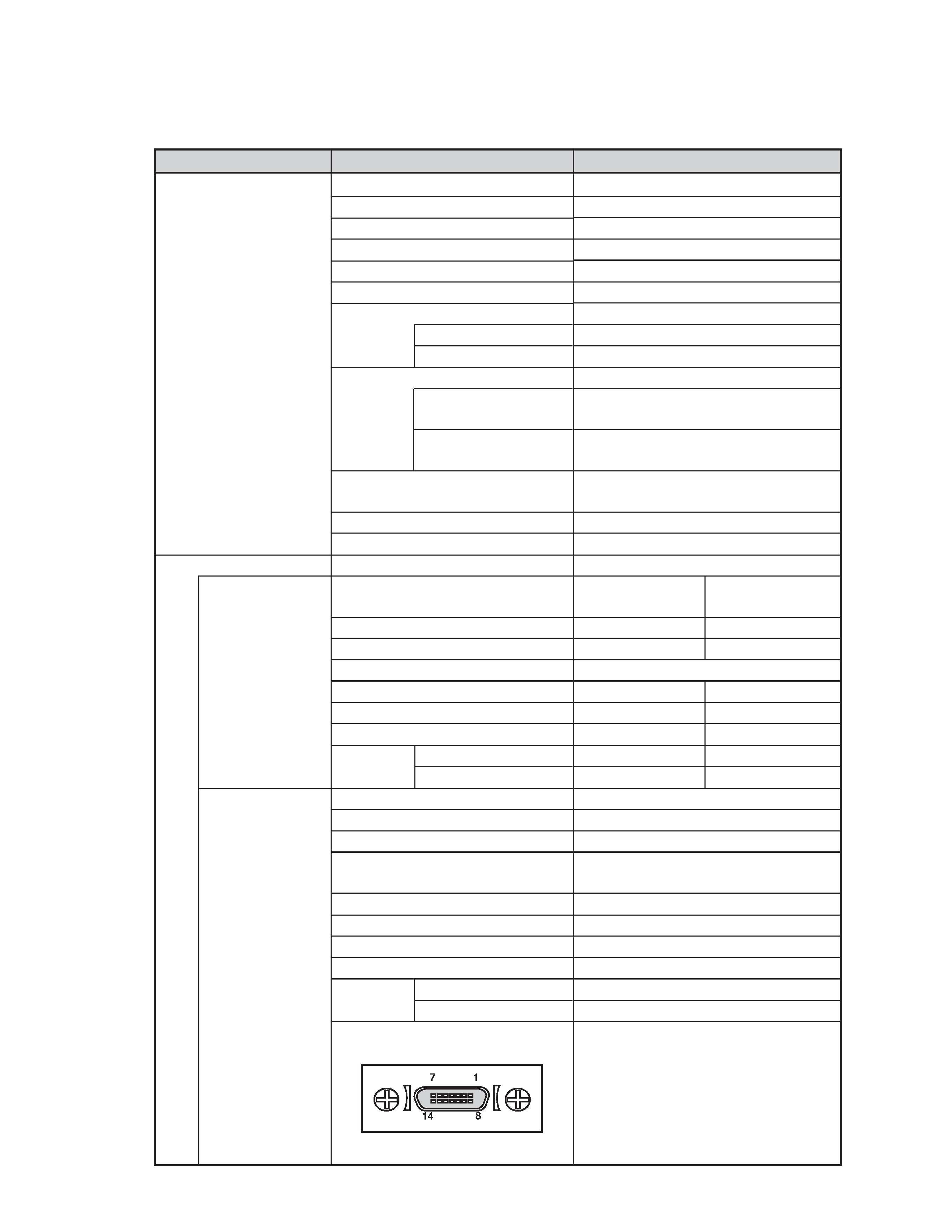
Signal pin assignment
Mark
Space
Semi-conductor laser
650 nm approx.
Less than 1mW
100 scans/sec approx.
Minimum 0.15 mm
0.45 or greater
0 ~ 300 mm
0 ~ 380 mm
Direct contact:
60 mm (max)
From 300 mm:
200 mm (max)
Direct contact:
65 mm (max)
From 380 mm:
250 mm (max)
WPC,NW7,CODE39,ITF,MSI,Industrial
2of 5,CODE93,CODE128,IATA
One (in colors of red and green)
Laser swing angle control
Conforms to IrDA
Casio original
Ver.1.2
Start/Stop
Start/Stop
Half duplex
Half duplex
2400/9600/19200/38400/57600/115200
8 bit
8 bit
1 bit
1 bit
1 bit
1 bit
LED Off
LED Off
LED On
LED On
Serial communication
Start/Stop
Full duplexes
300/600/1200/2400/4800/9600/19200/
38400/57600/115200
7 or 8 bit
1 bit
1 or 2 bit
None/Odd/Even
0 V
5 V
1 pin NC
8 pin CS
2 pin NC
9 pin CD
3 pin ER
10 pin RD
4 pin RS
11 pin GND
5 pin SD
12 pin CI
6 pin GND
13 pin NC
7 pin DR
14 pin GND
Laser Scanner
Communication
Block
Item
Specification
IrDA
14pin I/F
DT-900M50E
DT-900M51E
DT-900M50E
DT-900M51E
Mark
Space
Page 3
Power unit
Environment data
Dimensions and Weight
Temperature
Humidity
Wet splash proof
Drop durability
(height)
Dimensions
Weight
Battery type
Normal voltage
Normal capacity
Battery life
Condition of battery life
Backup duration
Battery type
Normal voltage
Normal capacity
Backup duration
Type
Detection voltage
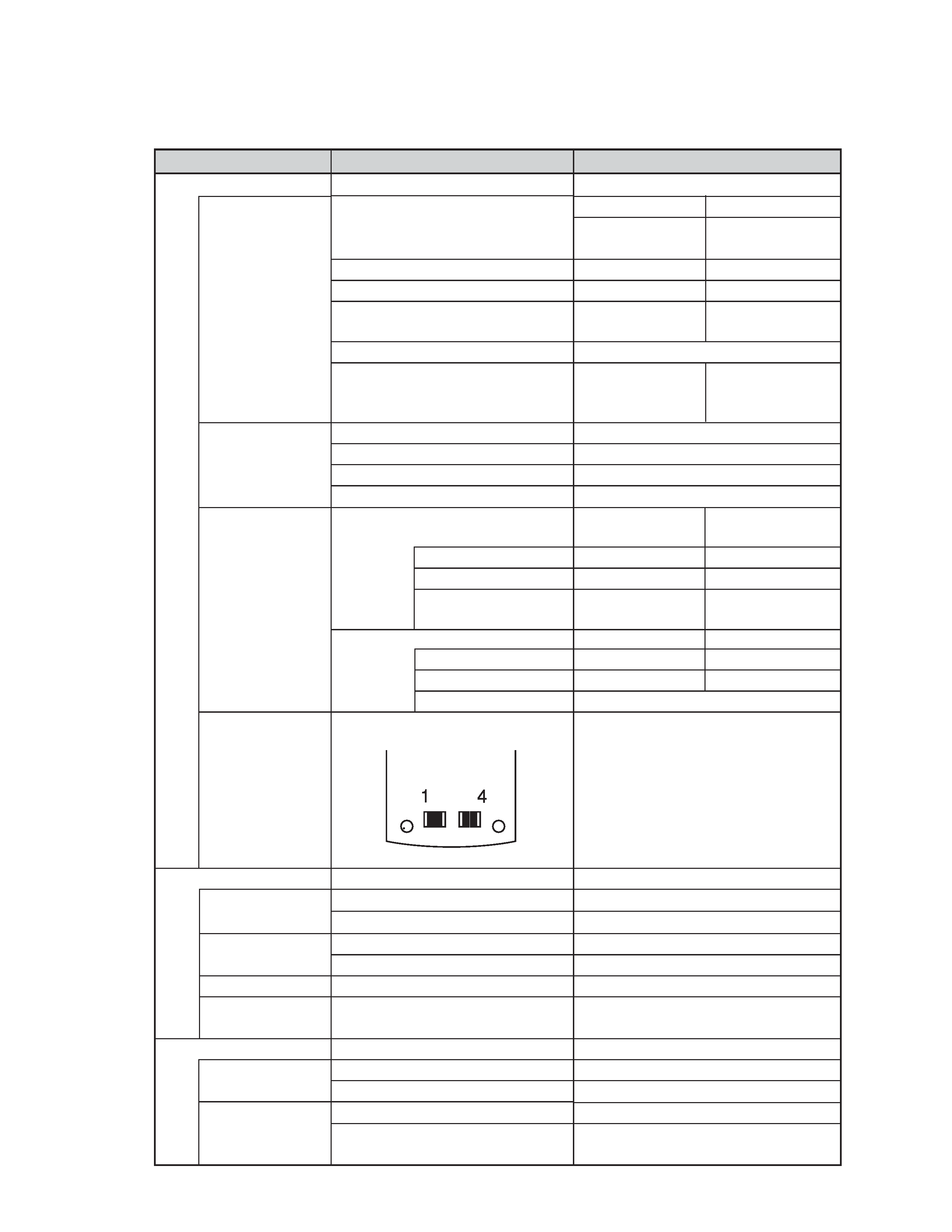
Signal pin assignment
Operating temperature
Storage temperature
Operating humidity
Storage humidity
DT-900M50E
DT-900M51E
DT-900M50E
DT-900M51E
LB0 (Main battery)
LB1 (Main battery)
LB2 (Sub battery)
Standard
Option
DC1.5 V
× 2
DC3.6 V
600 mAh
20 (Sleep) : 1 (Operating) : 1 (Scanning)
Lithium ion battery (CR2032)
× 1
DC3.0 V
210 mAh
1month approx at 25
°C (sub battery only)
Meaning
Battery exhausted
Forced OFF
Used up
Operable
Alkaline battery
Lithium ion battery
1.5 V
2.8 V
2.1 V
3.3 V
2.7 V
1pin VCHG
Recharge terminal 4.2V Max 300 mA
2pin XIRCNT
Control signal for IO box
3pin VADP
Power supply 5V Max 400 mA
4pin GND
Ground
5
°C ~ 50 °C
10
°C ~ 50 °C
30 % ~ 80 % RH
30 % ~ 90 % RH
Conforms to IPX2
150cm
179 (L)
× 56 (W) × 21.4 (H) mm (approx.)
173 (L)
× 56 (W) × 21.4 (H) mm (approx.)
210 g (approx.)
198 g (approx.)
Block
Item
Specification
Main battery
Sub battery
Low battery alarm
Recharge termi-
nals
5 months approx.
with new battery
and at 25
°C
1.5months approx.
with full charged and
at 25
°C
Operating condi-
tion
Used up or not in-
stalled
Memory backup
impossible
150hours approx.
at 25
°C
30hours approx.
at 25
°C
LB0 (Main battery)
LB1 (Main battery)
LB2 (Sub battery)
AA size alkaline
battery
× 2
Lithium ion battery
pack
× 1