(with price)
CTK-650
ELECTRONIC KEYBOARD
R
CTK-650
MC-Service

CONTENTS
SPECIFICATIONS ....................................................................................................1
BLOCK DIAGRAM ...................................................................................................2
CIRCUIT DESCRIPTION
CPU (HD6433298A16P : H8/329) .....................................................................3
DIGITAL SIGNAL PROCESSOR, LSI-S (HG51A115A01FD) ..........................4
KEY TOUCH LSI (HG52E35P) ..........................................................................5
POWER AMPLIFIER (LA4598) .........................................................................6
BUTTON MATRIX .............................................................................................
KEY MATRIX .....................................................................................................8
WIRING DIAGRAM ...................................................................................................
IC LEAD IDENTIFICATION AND INTERNAL CIRCUIT ..........................................10
PCB VIEW AND MAJOR WAVEFORMS .................................................................
SCHEMATIC DIAGRAM ...........................................................................................
PARTS LIST .............................................................................................................15
EXPLODED VIEW ....................................................................................................19
7
9
12
13

-- 1 --
Number of keys:
61
Polyphony:
32-note(max.)
Preset tones:
128
Magical preset:
BREAK BEAT
16
MELODYCOMP
8
SHADOW DRUM
4
FREE SESSION
32
TONE STACK
40
KEY SPLIT
12
HYPERACTIVE
16
Auto-accompaniment:
Rhythm patterns
128
Tempo
Adjustable(40 - 255)
Chords
Three system: CASIO CHORD, FINGERD,
FULL-RANGE CHORD
Other
Variation pattern, fill-in pattern, intro/ending pattern for each
rhythm.
Song memory:
song:one
System:Real-time recording
Memory capacity:Up to 1,300 notes
Registration memory:
4 setups
Sound control pads:
Phrases
10
Drums
10
SE/Percussion
10
Controller
2
Digital effects:
REVERB 1, REVERB 2, REVERB 3, CHORUS, TREMOLO, PHASE
SHIFTER, ORGAN SP, ENHANCER, FLANGER, EQLOUNDNESS
DEMO tunes:
3 tunes
Other functions:
Transpose (F# ~ C ~ F : half-note)
Tuning adjustable A4 = 440KHz 50 cents increments
Volume control (Main /Accompaniment)
Speakers:
12cm diameter X 2 (Output:2W+2W)
I/O terminals:
Power supply
9V DC jack
Headphones
Stereo mini jack
Output impedance:100 ohm
Output voltage:4.5V(RMS. max)
Assignable jack
Standard jack
MIDI
IN, OUT
Power supply:
3-way AC/DC power sources;
Batteries
Six D-size
Battry life
Approximately 5 hours on R20P(SUM-1)
AC
Required optional AD-5 AC adaptor
Car battery
Required optional CA-5 car adaptor
Auto power off:
Approximately 6 minutes after the last operation
Power consumption:
7.7W
Dimensions:
942 X 367 X 135 mm(HWD)
31 7/16" X 14 1/2" X 4 3/8" inches(HWD)
Weight:
5.2kg(11.7lbs) excluding batteries
Accessory:
Score stand
SPECIFICATION
MC-Service
-- 2 --
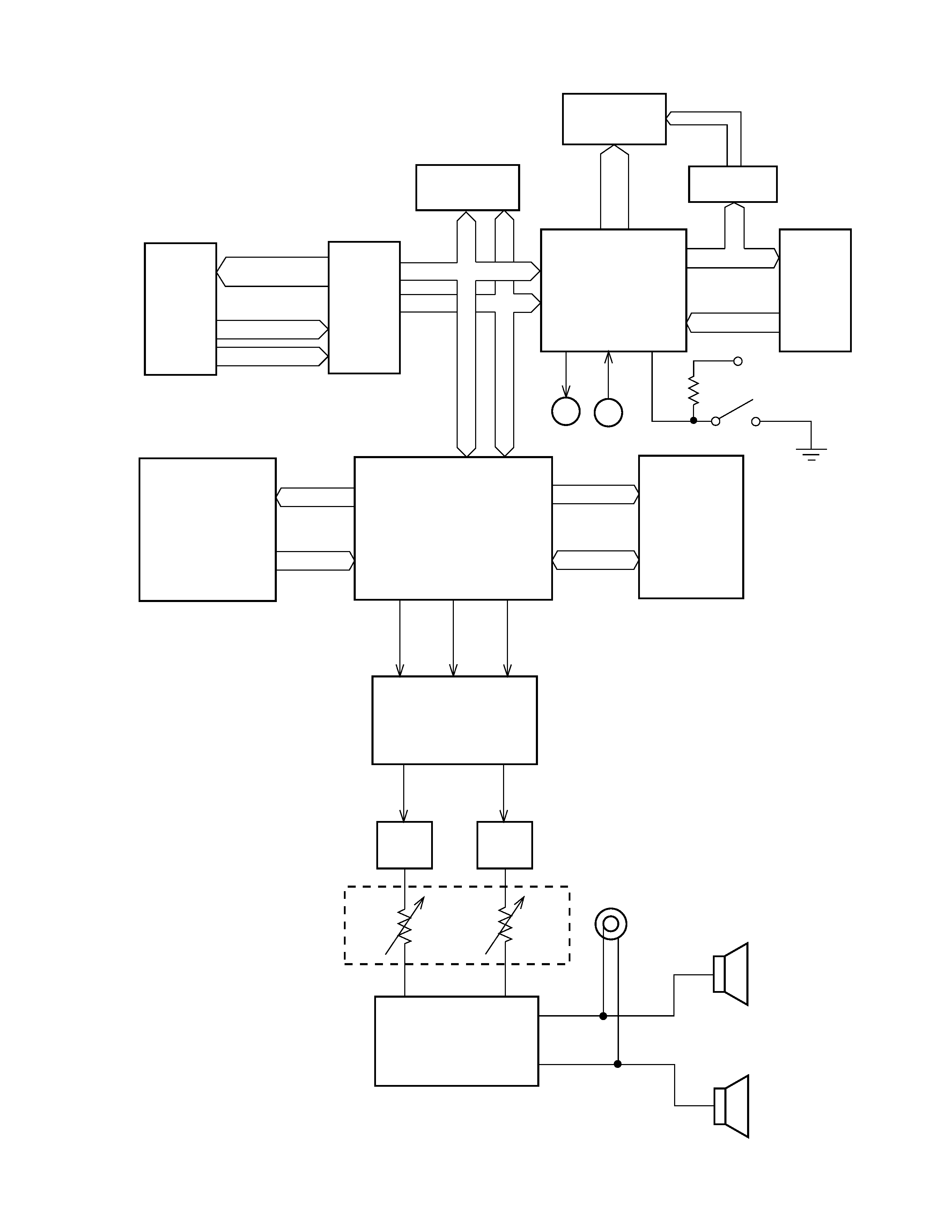
BLOCK DIAGRAM
Keyboard
KC0~KC7
SI0~SI7
FI0~FI7
Key Touch
LSI
HG52E35P
D0~D7
RAM-1(64K)
MN4464-08L-1
CPU
HD6433298A16P
(H8/329)
7-Segment
LED
LO0~LO4
LED driver
BA612
La
~Lp
KO0~KO5
Buttons
KI1~KI7
100K
VDD
Power Switch
MIDI
IN
OUT
RAM-2(64K)
MN4464-08L-2
EA0~EA12
ED0~ED7
LSI-S
HG51A115A01FD
RA0~RA19
RD0~RD15
ROM(16M)
TC5316200CP-C079
WCK1
SLOP
BCK
D/A Converter
µPD6376CX
Filter
Filter
Main
Volume
Power Amplifier
LA4598
Output
Speakers
Address Bus
KO0~4
-- 3 --
CIRCUIT DESCRIPTION
CPU(HD6433298A16P : H8/329)
The 16-bit CPU contains a 32K-byte ROM, a 1K-byte RAM, an 8-bit A/D converter, timers and I/O ports. The
CPU accesses to the DSP, Key Touch LSI, RAM, buttons and LEDs. But the CPU directly receives MIDI and
pedal signals.
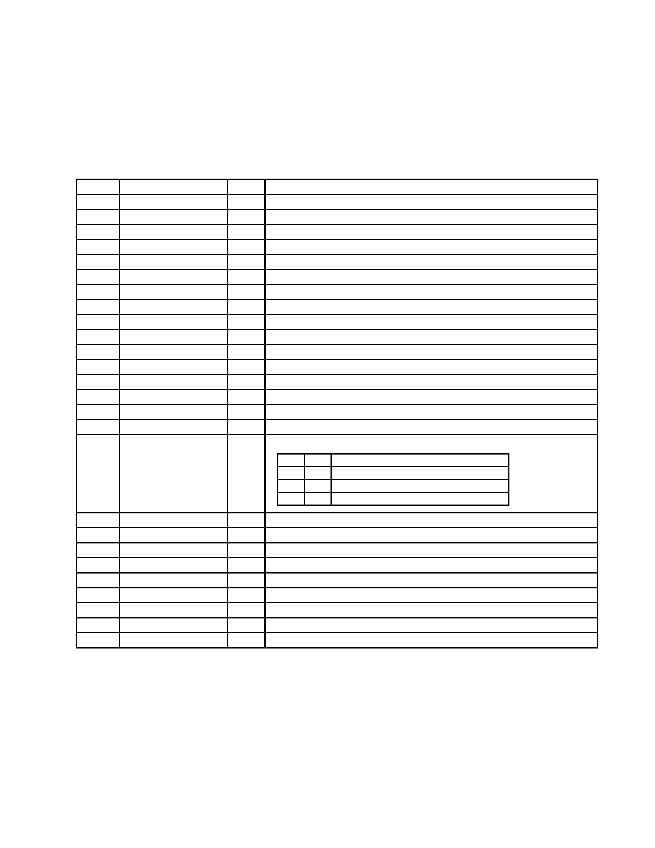
Pin No.
Terminal
In/Out
Function
1
P40/IRQ2
In
KO signal data.
2
P41/IRQ1
In
Timing signal for KO signal.
3
P42/IRQ0
In
APO signal output.
4
P43/-RD
Out
Read signal outpt.
5
P44/-WR
Out
Write signal output.
7
P46/PHI
Out
System clock output.
8
P47/-WAIT
In
Wait signal input
9
P50/Txd
Out
MIDI signal output.
10
P51/Rxd
In
MII signal input.
11
P52/SCK
Out
Reset signal output.
12
-RESET
In
Reset signal input.
13
-NMI
In
Power on signal input.(Low active)
14
Vcc
In
+5V source.
15
-STBY
In
Standby signal input. Connected to +5V.
16
Vss
In
Ground(0V) source.
17,18
XTAL,EXTAL
In/Out 20MHz clock pulse input/output. Connected to crystal.
19,20
MD1,MD0
In
Selection for system.
MD1 MD0
MODE
0
1
MODE-1 : Internal ROM mode
1
0
MODE-2 : Non internal ROM mode
1
1
MODE-3 : Single chip mode
21
AVss
In
Analog ground source.
22
P70/AN0
In
Connected to ground.
23~29
P71/AN0~P77/AN7
In
KI signal input.
30
AVcc
In
+5V source.
31~38 P60/FTCI~P67/TMO1
Out
Control signal for 7-segment LED.
39
Vcc
In
+5V source.
41~56
P26/A14~P10/A0
Out
Address bus.
48
Vss
In
Ground(0V) source.
57~64
P30/D0~P37/D7
In/Out Data bus.
MC-Service