SERVICE MANUAL
ELECTRONIC CASH REGISTER
(without price)
JANUARY 1997
CE-300 (EX-247)
Printer Model : MD-910

CONTENTS
Page
1. SPECIFICATIONS ................................................................................................ 1
2. INITIALIZE (MAC) OPERATION .......................................................................... 1
3. BLOCK DIAGRAM
3-1. PCB connection ......................................................................................... 2
3-2. Block diagram (circuit) .............................................................................. 3
4. CIRCUIT EXPLANATION
4-1. Power supply circuit .................................................................................. 4
4-2. CPU (uPD78052GC-093-3B9) .................................................................... 5
4-3. Display controller (uPD16312GB-3B4) ..................................................... 7
4-4. Initialize IC (Reset circuit) ......................................................................... 8
4-5. Power down detection circuit (PWD) ....................................................... 8
4-6. Address latch circuit ................................................................................. 8
4-7. RAM / ROM bank selection circuit ............................................................ 9
4-8. Head drive circuit for printer ................................................................... 10
4-9. Vpp sensor circuit .................................................................................... 11
4-10. Power supply circuit for display ............................................................. 11
5. DIAGNOSTIC
5-1. To start the diagnostic program ............................................................. 12
5-2. Check item ................................................................................................ 12
5-3. Operation of each test ............................................................................. 12
5-4. To exit the diagnostic test ....................................................................... 17
6. ERROR CODE
6-1. Operation error code ............................................................................... 18
6-2. System lock code..................................................................................... 19
7. IC DATA
1.
TC74HC00AP ............................................................................................ 20
2.
TC74HC08AP ............................................................................................ 20
3.
TC74HC138 ............................................................................................... 20
4.
TC74HC367AP .......................................................................................... 21
5.
TL431CLPB ............................................................................................... 21
6.
TC74HC373AP .......................................................................................... 21
7.
S-80745 / S-80719 ..................................................................................... 22
8.
M5237L ...................................................................................................... 22
9.
MAX232 ..................................................................................................... 22
8. PCB LAYOUT ..................................................................................................... 23
9. CIRCUIT DIAGRAMS ......................................................................................... 25
10. PARTS LIST ....................................................................................................... 41

-- 1 --
1. SPECIFICATIONS
Power consumption
120 V
220 V
230 V
240 V
In operation
Max.
0.28 A
0.17 A
0.16 A
0.15 A
Stand by
0.14 A
0.09 A
0.08 A
0.07 A
Mode SW OFF
Max.
0.12 A
0.08 A
0.07 A
0.06 A
Memory protection
Backup battery
Mangan Battery
UM-3
× 3 pcs.
Backup period
1 year (25
°C)
Battery life
Replace the battery every 1 year.
Memory capacity
32 KB
CXK58257AP-70/10L
Clock and calender
Accuracy
Within
±30 sec. per month (25 °C)
Auto calender
Effective until 2099 A.D.
Environment
Operating temperature
0
°C~ 40 °C
Operating humidity
10 % ~ 90 %
Storage temperature
-25
°C~ 65 °C
Storage humidity
10 % ~ 95 %
Printer
Model
MD-910-SSC
Print method
Dot matrix printing
Print digits
24 digits
MCBF
1,500,000 lines
Ink cassette
Life
250,000 characters
Roll paper
Type
Fine-quality paper or Pressure-sensitive copy paper
Size
57.5
±0.5 mm
Roll diameter
83 mm or less
2. INITIALIZE (MAC) OPERATION
1. Set the mode switch to "OFF" position.
2. Pressing the "FEED" button and turn the mode switch to "PRG" position.
3. Release the "FEED" button.
4. Press "#2" key (Normally "SUB TOTAL" key).
5. Initialize operation is executed.
-- 2 --
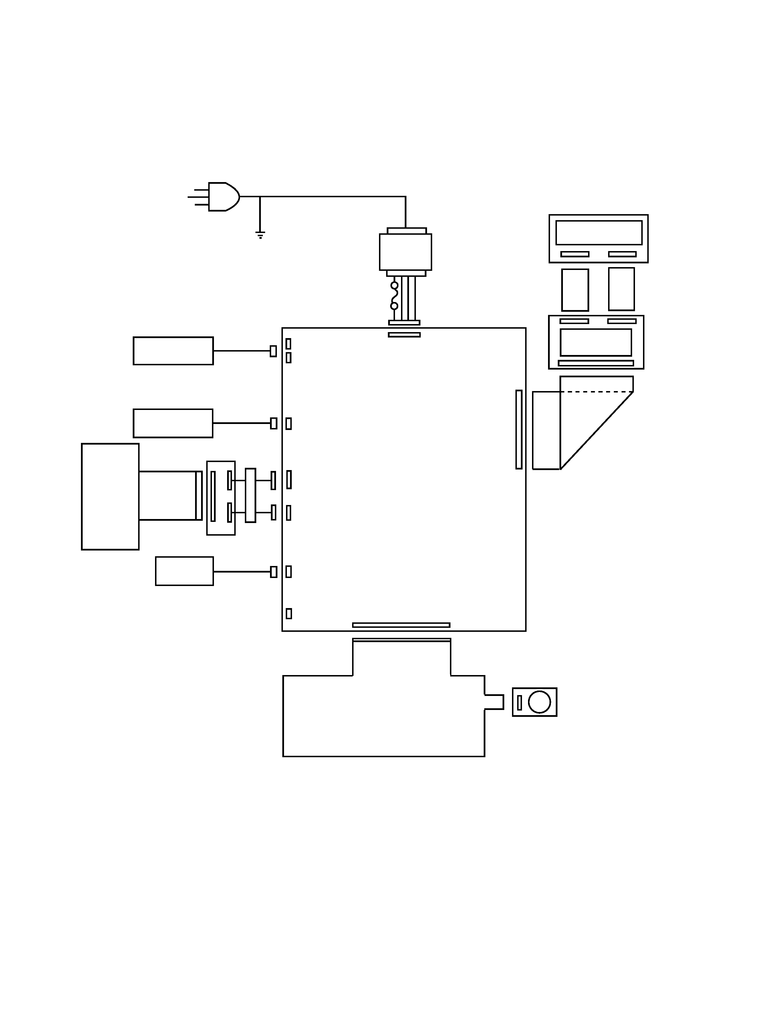
FPC
Mode SW
E266-E3-1
CN3
24P
Main Display
(SH101MA)
E278-E2-1
12P
10P
Rear Display
(SH1019A)
E278-E2-2
4P
Fuse
Transformer
3P
CN7
CN6
CN4
2P
17P
CN13
CN14
3P
CN2
(RS232C)
CN17
CN16
25P
9P
Mangan Battery
(UM-3
× 3)
Winder
Motor
Printer
(MD910SSC)
Drawer
E247-CNB
CORE
2 turn
10P
7P
E247-1
3. BLOCK DIAGRAM
3-1. PCB connection
-- 3 --
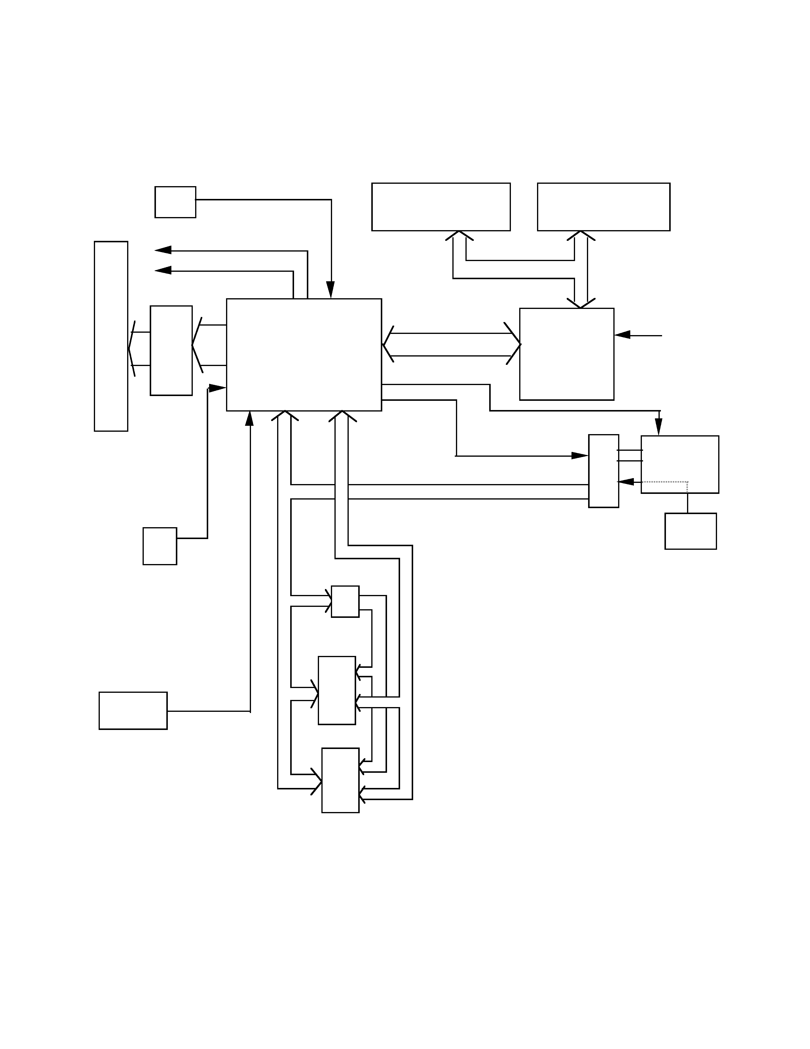
MAIN DISPLAY
CUSTOMER DISPLAY
SH101MA
SH1019A
Segment & Digit data
uPD16312GB-
3B4
DRWS
Mode
Key
Keyboard
FPC
A8~A15
AD0~AD7
ROM
RAM
A0~A7
CPU
uPD78052GC-093-3B9
MD
WD
Reset circuit
S80719AN
Head drive cuicuit
HD.A~HD.H
PWD detection
RS232C circuit
Printer
MD-910
DI,DO,CLK,STB
KC0~KC4
AD0~AD5
Select addess
3-2. Block diagram (circuit)