Handheld Personal Computer
A-20(ZX-340)
R
DEC. 1997
(without price)
A-20

CONTENTS
HARDWARE SPECIFICATIONS -------------------------------------------------------------- 1
General Specifications ------------------------------------------------------------------- 1
Electrical Specifications----------------------------------------------------------------- 2
ACCESSORIES ------------------------------------------------------------------------------------ 3
OPTIONS --------------------------------------------------------------------------------------------- 3
SYSTEM CONFIGURATION -------------------------------------------------------------------- 4
GENERAL GUIDE --------------------------------------------------------------------------------- 5
ADJUSTING DISPLAY CONTRAST --------------------------------------------------------- 6
DESKTOP COMPUTER SYSTEM CONFIGURATION ---------------------------------- 7
SETTING UP ---------------------------------------------------------------------------------------- 7
REPLACING BATTERIES ----------------------------------------------------------------------- 9
To replace the main batteries---------------------------------------------------------- 9
To replace the backup battery------------------------------------------------------- 10
RESET ---------------------------------------------------------------------------------------------- 11
To reset the CASSIOPEIA ------------------------------------------------------------- 11
FULL RESET -------------------------------------------------------------------------------------- 12
To perform a full reset ----------------------------------------------------------------- 12
CONNECTING TO A DESKTOP COMPUTER ------------------------------------------- 13
To connect to a desktop computer ------------------------------------------------ 13
REPLACING THE PC CARD ----------------------------------------------------------------- 14
To replace the PC card----------------------------------------------------------------- 14
REPLACING THE COMPACTFLASH CARD -------------------------------------------- 15
To replace the CompactFlash card ------------------------------------------------ 15
CONNECTING TO EXTERNAL EQUIPMENT ------------------------------------------- 16
To connect external equipment ----------------------------------------------------- 16
MEMORY BACKUP / RESTORE ------------------------------------------------------------ 17
Backup -------------------------------------------------------------------------------------- 17
Restore -------------------------------------------------------------------------------------- 19
BLOCK DIAGRAM ------------------------------------------------------------------------------ 21
DEVICE FEATURES ---------------------------------------------------------------------------- 22
LSI/IC DATA -------------------------------------------------------------------------------------- 24
SH-7093 (CPU / IC1) --------------------------------------------------------------------- 24
MB87A915 (Gate Array/IC3) ---------------------------------------------------------- 27
MC34119 (IC9)----------------------------------------------------------------------------- 32
MAX3241CAI (IC5) ----------------------------------------------------------------------- 32
UPD42S16160LG5 ----------------------------------------------------------------------- 33
RN5VD18CA (IC113) -------------------------------------------------------------------- 33
XC61A Series (IC100 ~ IC103,IC107,IC109,IC110,IC112) -------------------- 33
MAX608 (IC105,IC106) ------------------------------------------------------------------ 34
EMI FILTER ARRAY --------------------------------------------------------------------- 34
UPD23C32000LGY ----------------------------------------------------------------------- 34

* Windows is a registered trademark of Microsoft Corporation in the U.S.A. and other countries.
* i486DX and Pentium are registered trademarks of Intel Corporation.
POWER SUPPLY CIRCUIT ------------------------------------------------------------------- 35
Primary Circuit---------------------------------------------------------------------------- 35
5 V Circuit ---------------------------------------------------------------------------------- 36
3 V Circuit ---------------------------------------------------------------------------------- 37
PCMCIA Circuit --------------------------------------------------------------------------- 38
LCD power Circuit ----------------------------------------------------------------------- 39
Voltage Line ------------------------------------------------------------------------------- 40
DETECTOR CIRCUIT --------------------------------------------------------------------------- 41
DIAGNOSTIC PROGRAM --------------------------------------------------------------------- 42
Introduction-------------------------------------------------------------------------------- 42
OPERATION CHECK --------------------------------------------------------------------------- 43
IrDA Communication Test ------------------------------------------------------------ 48
Current Consumption and Voltage Detectors Check ------------------------ 50
Voltage Detectors Check -------------------------------------------------------------- 52
DISASSEMBLY · ASSEMBLY --------------------------------------------------------------- 54
1.Module ------------------------------------------------------------------------------------ 54
2.Upper case ass'y ---------------------------------------------------------------------- 55
3.Removal of touch panel and LCD unit ----------------------------------------- 57
4.Precautions when installing LCD unit------------------------------------------ 60
5.Installation of shaft piece----------------------------------------------------------- 61
6.How to pass FPC through the upper case ------------------------------------ 62
7.Precautions when assembling---------------------------------------------------- 63
EXPLOED VIEW --------------------------------------------------------------------------------- 65
PARTS LIST --------------------------------------------------------------------------------------- 66
WIRING DIAGRAM ------------------------------------------------------------------------------ 68
PCB VIEW ----------------------------------------------------------------------------------------- 69
SCHEMATIC DIAGRAMS --------------------------------------------------------------------- 70
Z340-1 PCB 1/3 (MAIN) ----------------------------------------------------------------- 70
Z340-1 PCB 2/3 (POWER SUPPLY) ------------------------------------------------ 71
Z340-1 PCB 3/3 (DP I/F BLOCK)----------------------------------------------------- 72
Z370-ROM PCB (ROM) ----------------------------------------------------------------- 73
Z340-DPMI PCB (MIC) ------------------------------------------------------------------ 74
Z340-LED PCB (LED) ------------------------------------------------------------------- 75
KEY MATRIX------------------------------------------------------------------------------- 76

-- 1 --
HARDWARE SPECIFICATIONS
General Specifications
Model:
A-20
Display:
640
× 240 dots/0.24 dot pitch, FSTN LCD, 4 grayscale monochrome
CPU:
SH3
Memory
RAM:
8M bytes
ROM:
8M bytes
Speaker:
Sound
Interfaces:
RS-232C: 115.2K BPS
Data communication jack
PC card slot
CompactFlash card slot
Infrared port (IrDA compatible protocol)
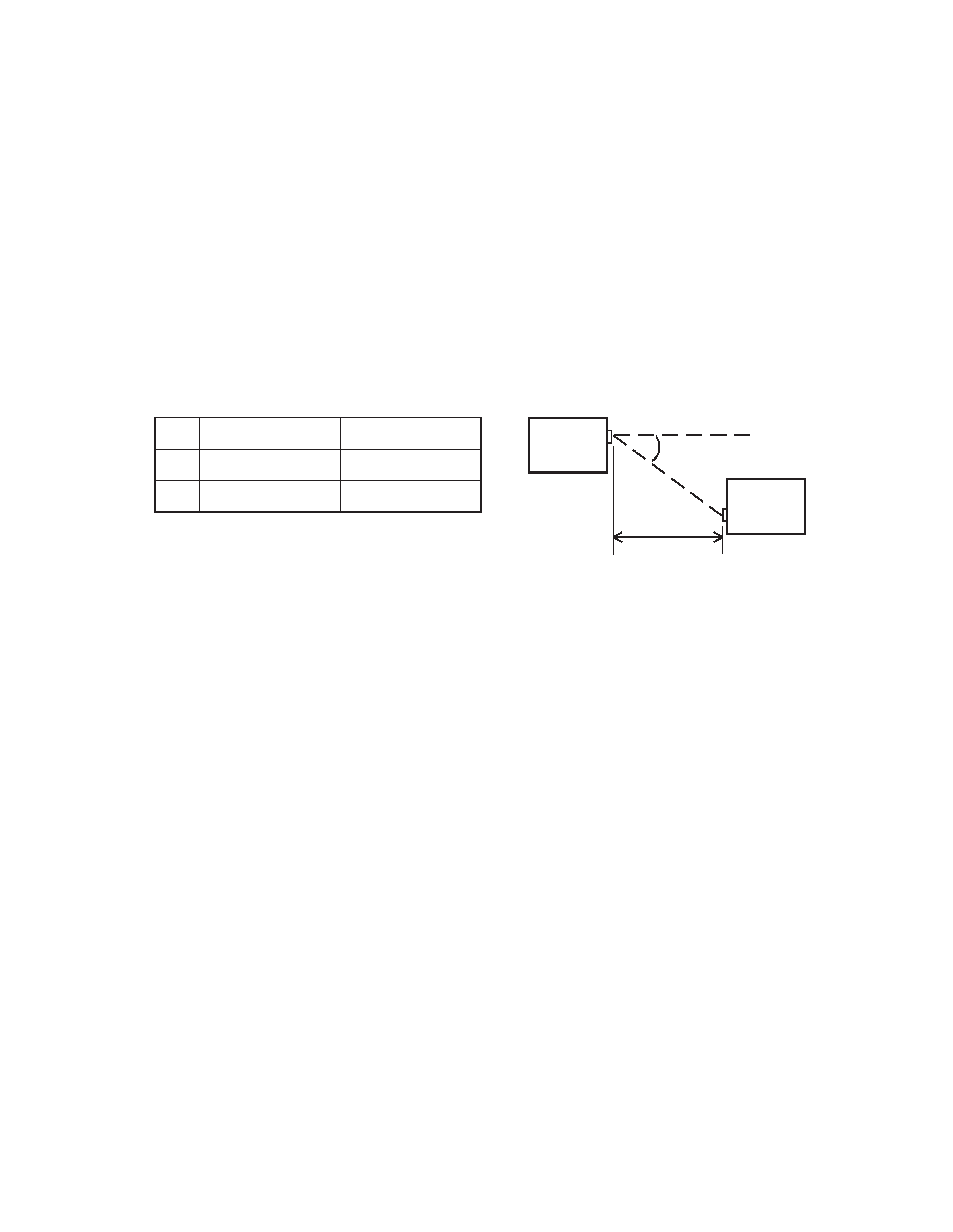
Communication distance: 10 to 70 cm
Maximum Speed: 115.2K BPS
Power Supply:
Main
Two AA-size alkaline batteries LR6 (AM3);rechargeable battery pack(A-B10LT);
AC adaptor (AD-C50200)
Back-up
One CR2032 lithium battery
Power Consumption: 3.0 W
Battery Life:
Main
Two AA-size alkaline batteries: 25 hours (in Word, continuous cycle of one-
minute input and 10-minutes input standby), 10 hours (input of 90 characters
per minutes in Word)
Rechargeable battery pack: 15 hours (in Word, continuous cycle of one-minute
input and 10-minutes input standby), 10 hours (input of 90 characters per min-
utes in Word)
* Main Battery life is shortened considerably by use of a modem card or any
other high power consumption PC card.
Back-up
5 year (when main battery is replaced immediately after appearance of low
battery message)
1 month (when unit is left without a main battery)
Operating Temperature:
0
°C to 40 °C (32 °F to 104 °F)
Dimensions (excluding projections):
Folded:
24.5H
× 185W × 94D mm (1"H × 7-1/4"W × 3-11/16"D)
Weight:
430 g (15.2 oz) including batteries
-- 2 --
No.
Length (L)
Angle (A)
1
L = 80 cm
A =
±15 degree
2
L = 10 cm
A = 0 degree
A
L
A-20
A-20
Electrical Specifications
Current Consumption (V-in: 2.6 V
± 0.1 V, LCD Contrast VR: MID.):
Main Battery: Diagnostics Program with alkaline batteries
80 MHz:
650 mA or under
Sleep:
50 mA or under
Standby:
1.4 mA or under
Back-up Battery:
OFF:
450
µA
Voltage Detectors:
VDET1:
2.0 V
± 1% V or under (Low battery message detector for alkaline batteries)
VDET2:
1.6 V
± 1% V or under (Foced power off detector for alkaline batteries)
VDET1R:
3.3 V
± 2% V or under (Low battery message detector for rechargeable battery)
VDET2R:
3.0 V
± 2% V or under (Foced power off detector for rechargeable battery)
VDETS:
2.7 V
± 1% V or under (Low battery message detector for back-up battery)
IrDA: