
FY8-13F4-000
FEB. 1998
COPYRIGHT © 1998 CANON INC.
CANON NP6621 REV.0 FEB. 1998 PRINTED IN JAPAN (IMPRIME AU JAPON)
SERVICE
MANUAL
REVISION 0

COPYRIGHT
© 1998 CANON INC.
CANON NP6621 REV.0 FEB. 1998 PRINTED IN JAPAN (IMPRIME AU JAPON)
COPYRIGHT © 1998 CANON INC.
Printed in Japan
Imprimé au Japon
Use of this manual should be
strictly supervised to avoid
disclosure of confidential
information.
Prepared by
OFFICE IMAGING PRODUCTS TECHNICAL SUPPORT DEPARTMENT 1
OFFICE IMAGING PRODUCTS TECHNICAL SUPPORT DIVISION
CANON INC.
5-1, Hakusan 7-chome, Toride-shi Ibaraki, 302-0023 Japan
IMPORTANT
THE INFORMATION CONTAINED HEREIN IS PUBLISHED BY CANON, INC., JAPAN, AND IS
FOR REFERENCE USE ONLY. SPECIFICATIONS AND OTHER INFORMATION CONTAINED
HEREIN MAY VARY SLIGHTLY FROM ACTUAL MACHINE VALUES OR THOSE FOUND IN
ADVERTISING AND OTHER PRINTED MATTER.
ANY QUESTIONS REGARDING INFORMATION CONTAINED HEREIN SHOULD BE DIRECTED
TO THE COPIER SERVICE DEPARTMENT OF THE SALES COMPANY.

Introduction
i
COPYRIGHT
© 1998 CANON INC.
CANON NP6621 REV.0 FEB. 1998 PRINTED IN JAPAN (IMPRIME AU JAPON)
This Service Manual provides basic facts and figures you will need to service the plain paper copier
NP6621 in the field.
The NP6621 is designed to enable automated copying work and may be configured with the following
accessory; for servicing information on the sorter, ADF, and control card, see their respective Service
Manuals:
1. Cassette Feeding Module-B2
2. Cassette Feeding Module-A2
3. Cassette Feeding Unit-K1
4. Paper Deck Pedestal-K1
5. Control Card IV N
6. ADF-E1
7. RDF-F1
8. Stapler Sorter-D1
9. Sorter 10-B1
10. Remote Diagnostic Device II
This Service Manual contains descriptions on the 1-Cassette Feeding Unit-B1 and the 2-Cassette Feeding
Unit-A2.
Note:
The Cassette Feeding Unit-B2, the Cassette Feeding Unit-A2 the cassette feeding Unit K1, the Paper
Deck Pedestal-K1 and Remote Diagnostic Device II may not be available for sale in some areas.
This Service Manual is organized as follows:
CHAPTER 1, "General Introduction," explains the NP6621's features, specifications, and step-by-step
instructions on how to operate the copier.
CHAPTER 2, "Copying Processes," shows how the NP6621 generates copies while discussing each of
the steps involved.
CHAPTER 3, "Operations and Timing," explains the NP6621's mechanical system by function and
principles behind its electrical system in relation to timing of each operation.
CHAPTER 4, "Mechanical System," provides instructions on how to disassemble/assemble and adjust the
NP6621.
CHAPTER 5, "Installation," provides points to note when selecting the site of installation and instructions
on how to install the NP6621.
CHAPTER 6, `Maintenance and Inspection," gives tables of periodically replaced parts and consumables/
durables as well as a scheduled servicing chart.
APPENDIX contains a general timing chart, general circuit diagrams, and PCB diagrams.
This Service Manual is accompanied by the Service Handbook, which provides information on how to
maintain and inspect the NP6621 through adjustment and troubleshooting work.
Information found in this manual may be updated from time to time for product improvement, and major
updates are communicated in the form of
Service Information bulletins.
All service persons are expected to be thoroughly familiar with this Service Manual, the Service Handbook,
and Service Information bulletins and be ready to respond to the needs of the user.
ii
Introduction
COPYRIGHT
© 1998 CANON INC.
CANON NP6621 REV.0 FEB. 1998 PRINTED IN JAPAN (IMPRIME AU JAPON)
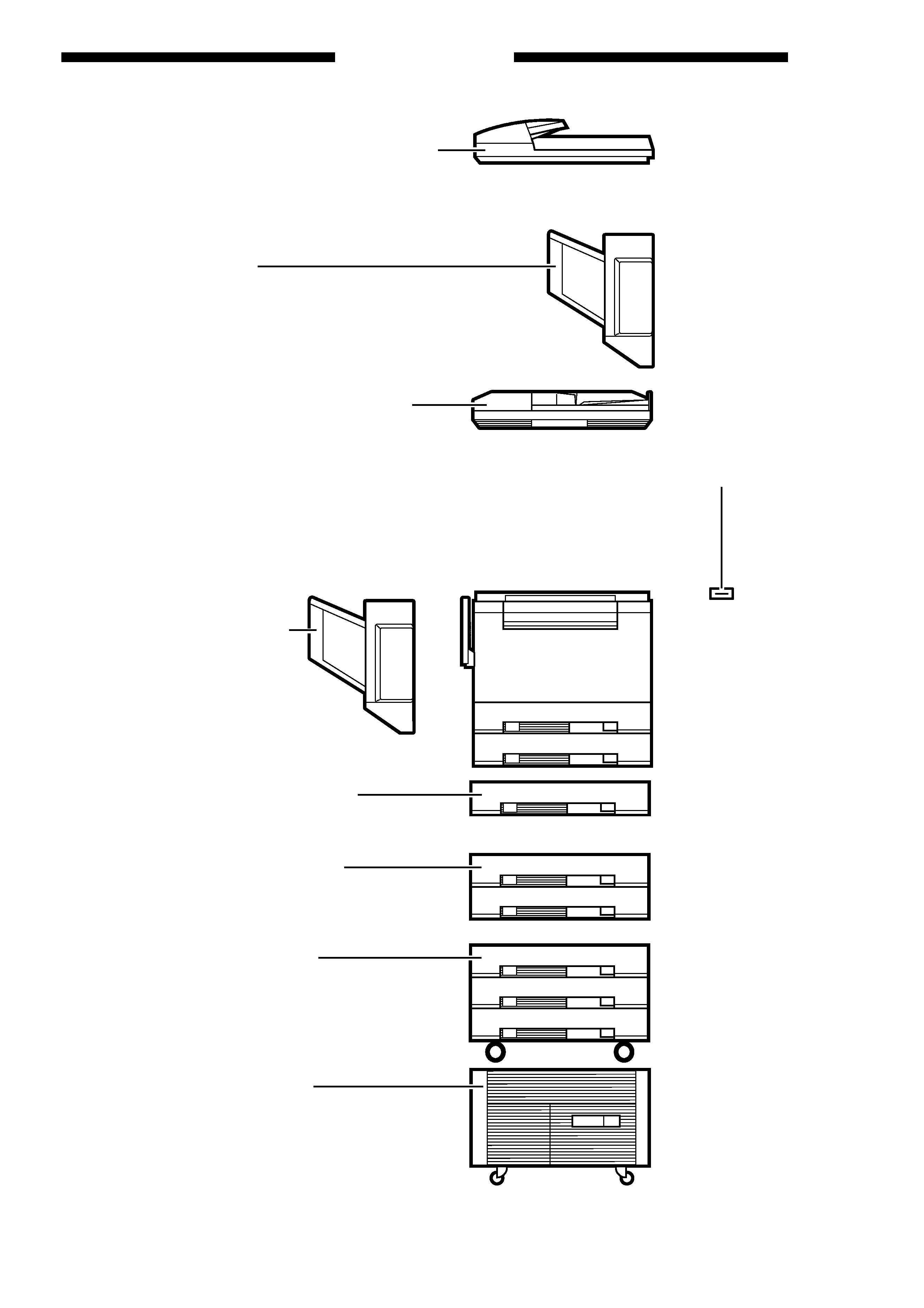
RDF-F1 (Recirculating Document Feeder)
Automatically feeds a set of up to 100 originals to the
platen glass for copying. The RDF can also turn over
two-sided originals for automatic two-sided copying.
MS-B1 (10 bins)
Automotically sorts and groups sets of up to
10 copies.
ADF-E1 (Automatic Document Feeder)
Automatically feeds sets of up to 30 originals to
the copyboard for copying.
Stapler Sorter-D2 (10 bins)
Automatically sorts or groups copies
into 10 bins at (30 pages per set).
Staples sets of up to 20 copies
each.
Control Card IV N
Allows you to monitor the number of
copies made by each card holder.
Cassette Feeding Module-A2
Allows you to increase your paper supply
through the addition of two paper cassettes.
Cassette Feeding Module-B2
Allows you to increase your paper supply
through the addition of one paper cassette.
Cassette Feeding Unit-K1
Allows you to increase your
paper supply through the addition
of three paper cassettes.
Paper Deck Pedestal-K1
Holds up to 1500 sheets of one type of paper.

iii
COPYRIGHT
© 1998 CANON INC.
CANON NP6621 REV.0 FEB. 1998 PRINTED IN JAPAN (IMPRIME AU JAPON)
CONTENTS
CHAPTER 1
GENERAL DESCRIPTION
I.
FEATURES ................................................ 1-1
II. SPECIFICATIONS ..................................... 1-2
A. Copier .................................................. 1-2
B. Cassette Feeding Module-B2/
Cassette Feeding Module-A2/Cassette
Feeding Unit-K1 .................................. 1-5
C. Paper Deck Pedestal-K1 ..................... 1-6
III. NAMES OF PARTS ................................... 1-7
A. Exterior ................................................ 1-7
B. Cross Section ...................................... 1-8
IV. BASIC OPERATION ................................ 1-13
A. Control Panel ..................................... 1-13
B. Making Copies ................................... 1-16
C. Using the Stack Bypass .................... 1-17
D. User Mode ......................................... 1-19
V. WARNINGS AND ACTIONS ................... 1-26
A. Jam Indicator ..................................... 1-26
B. Cleaning the Static Charge
Eliminator ........................................... 1-33
VI. ROUTINE CLEANING ............................. 1-34
I.
IMAGE FORMATION ................................ 2-1
A. Outline ................................................. 2-1
B. Latent Static Image Formation Block .... 2-2
C. Step 1 (pre-exposure) ......................... 2-3
D. Step 2 (primary charging) .................... 2-3
E. Step 3 (image exposure) ..................... 2-4
F. Step 4 (development) .......................... 2-4
G. Step 5 (transfer) .................................. 2-5
H. Step 6 (separation) .............................. 2-6
I.
Step 7 (fixing) ...................................... 2-7
J. Step 8 (drum cleaning) ........................ 2-7
II. AUXILIARY PROCESS ............................. 2-8
A. Blank Exposure ................................... 2-8
CHAPTER 2
COPYING PROCESS
CHAPTER 3
OPERATIONS AND TIMING
I.
BASIC OPERATIONS ............................... 3-1
A. Functional Construction ....................... 3-1
B. Outline of Electrical Circuitry ............... 3-2
C. Inputs to the DC Controller .................. 3-3
D. Outputs from the DC Controller ........... 3-8
E. Inputs to and Outputs from the Cassette
Feeding Module-B2 Driver PCB ........ 3-13
F. Inputs to and Outputs from the Cassette
Feeding Module-A2 Driver PCB ........ 3-14
G. Inputs to and Outputs from the Cassette
Feeding Unit-K1 Driver PCB ............. 3-16
H. Main Motor Control Circuit ................. 3-21
I.
Basic Sequence of Operations
(2 copies, continuous, AE) ................ 3-22
J. Original Size Detecton Control .......... 3-23
II. EXPOSURE SYSTEM ............................. 3-27
A. Varying the Reproduction Ratio ........ 3-27
B. Lens Drive System ............................ 3-27
C. Scanner Drive System ....................... 3-31
D. Operations of the Scanner in Page
Separation Mode ............................... 3-34
III. IMAGE FORMATION SYSTEM .............. 3-35
A. Outline ............................................... 3-35
B. Sequence of Operations
(image formation system) .................. 3-36
C. Controlling the Scanning Lamp ......... 3-37
D. Controlling the Primary Charging
Roller ................................................. 3-38
E. Controlling the Transfer Roller Bias .... 3-41
F. Controlling the Static Eliminator
Bias .................................................... 3-44
G. Controlling the Developing Bias ........ 3-46
H. Copy Density Automatic Control ....... 3-48
I.
Developing/Cleaning Assembly ........ 3-50
J. Blank Exposure Control ..................... 3-53
K. Primary Charging Roller Cleaning
Control ............................................... 3-55
L. Transfer Roller Locking/Releasing
Control ............................................... 3-56
IV. PICK-UP/FEEDING SYSTEM ................. 3-57
A. Pick-Up from the Machine ................. 3-57
B. Making Two-Sided Copies (1copy) ... 3-61