COPYRIGHT © 1999 CANON INC.
CANON NP6320 REV.0 DEC. 1999 PRINTED IN JAPAN (IMPRIME AU JAPON)
REVISION 0
FY8-13GF-000
DEC. 1999

COPYRIGHT © 1999 CANON INC.
CANON NP6320 REV.0 DEC. 1999 PRINTED IN JAPAN (IMPRIME AU JAPON)
IMPORTANT
THIS DOCUMENTATION IS PUBLISHED BY CANON INC., JAPAN, TO SERVE AS A SOURCE
OF REFERENCE FOR WORK IN THE FIELD.
SPECIFICATIONS AND OTHER INFORMATION CONTAINED HEREIN MAY VARY SLIGHTLY
FROM ACTUAL MACHINE VALUES OR THOSE FOUND IN ADVERTISING AND OTHER
PRINTED MATTER.
ANY QUESTIONS REGARDING INFORMATION CONTAINED HEREIN SHOULD BE DIRECTED
TO THE COPIER SERVICE DEPARTMENT OF THE SALES COMPANY.
THIS DOCUMENTATION IS INTENDED FOR ALL SALES AREAS, AND MAY CONTAIN INFOR-
MATION NOT APPLICABLE TO CERTAIN AREAS.
COPYRIGHT © 1999 CANON INC.
Printed in Japan
Imprimé au Japon
Use of this manual should be strictly su-
pervised to avoid disclosure of confidential
information.
Prepared by
OFFICE IMAGING PRODUCTS TECHNICAL SUPPORT DIVISION
OFFICE IMAGING PRODUCTS QUALITY ASSURANCE CENTER
CANON INC.
5-1, Hakusan 7-chome, Toride-shi, Ibaraki 302-8501 Japan

COPYRIGHT © 1999 CANON INC.
CANON NP6320 REV.0 DEC. 1999 PRINTED IN JAPAN (IMPRIME AU JAPON)
i
This Service Manual contains basic data and figures for the NP6320 needed to
service the machine in the field.
Chapter 1
General Description introduces the copier's features and specifications,
shows how to operate the copier, and explains how copies are made.
Chapter 2
Basic Operation provides outlines of the copier's various operational
workings.
Chapter 3
Exposure System discusses the principles of operation used for the copier's
lens drive unit and scanner drive unit. It also explains the timing at which
these drive units are operated, and shows how they may be disassembled/
assembled and adjusted.
Chapter 4
Image Formation System discusses the principles of how images are formed.
It also explains the timing at which the various units involved in image
formation are operated, and shows how they may be disassembled/
assembled and adjusted.
Chapter 5
Pick-Up/Feeding System explains the principles used from when copy paper
is picked up to when a copy is delivered in view of the functions of electrical
and mechanical units ahd in relation to their timing of operation. It also shows
how these units may be disassembled/assembled and adjusted.
Chapter 6
Fixing System explains the principles used to fuse toner images to tranfer
media in view of the functions of electrical and mechanical units and in
relation to their timing of operation. It also shows how these units may be
disassembled/assembled and adjusted.
Chapter 7
Externals/Auxiliary Mechanisms shows the copier's external parts, and
explains the principles used for the copier's various control mechanisms in
view of the functions of electrical and mechanical units and in relation to their
timing of operation. It also shows how these units may be disassembled/
assembled and adjusted.
Chapter 8
Installation introduces requirements for the site of installation, and shows
how the copier may be installed using step-by-step instructions.
Chapter 9
Maintenance and Servicing provides tables of periodically replaced parts and
consumables/durables and scheduled servicing charts.
Chapter 10
Troubleshooting provides tables of maintenance/inspection, standards/
adjustments, and problems identification (image fault/malfunction).
Appendix contains diagrams showing electrical parts arrangement, tables of
signals, tables of special tools, tables of solvents/oils, and a general timing
chart.
The descriptions in this Service Manual are subject to change without notice for
product improvement or other purposes, and major changes will be communicated in the
from of Service Information bulletins.
All service persons are expected to have a good understanding of the contents of this
Service Manual and all relevant Service Information bulletins and be able to identify and
isolate faults in the machine.
INTRODUCTION
COPYRIGHT © 1999 CANON INC.
CANON NP6320 REV.0 DEC. 1999 PRINTED IN JAPAN (IMPRIME AU JAPON)
ii
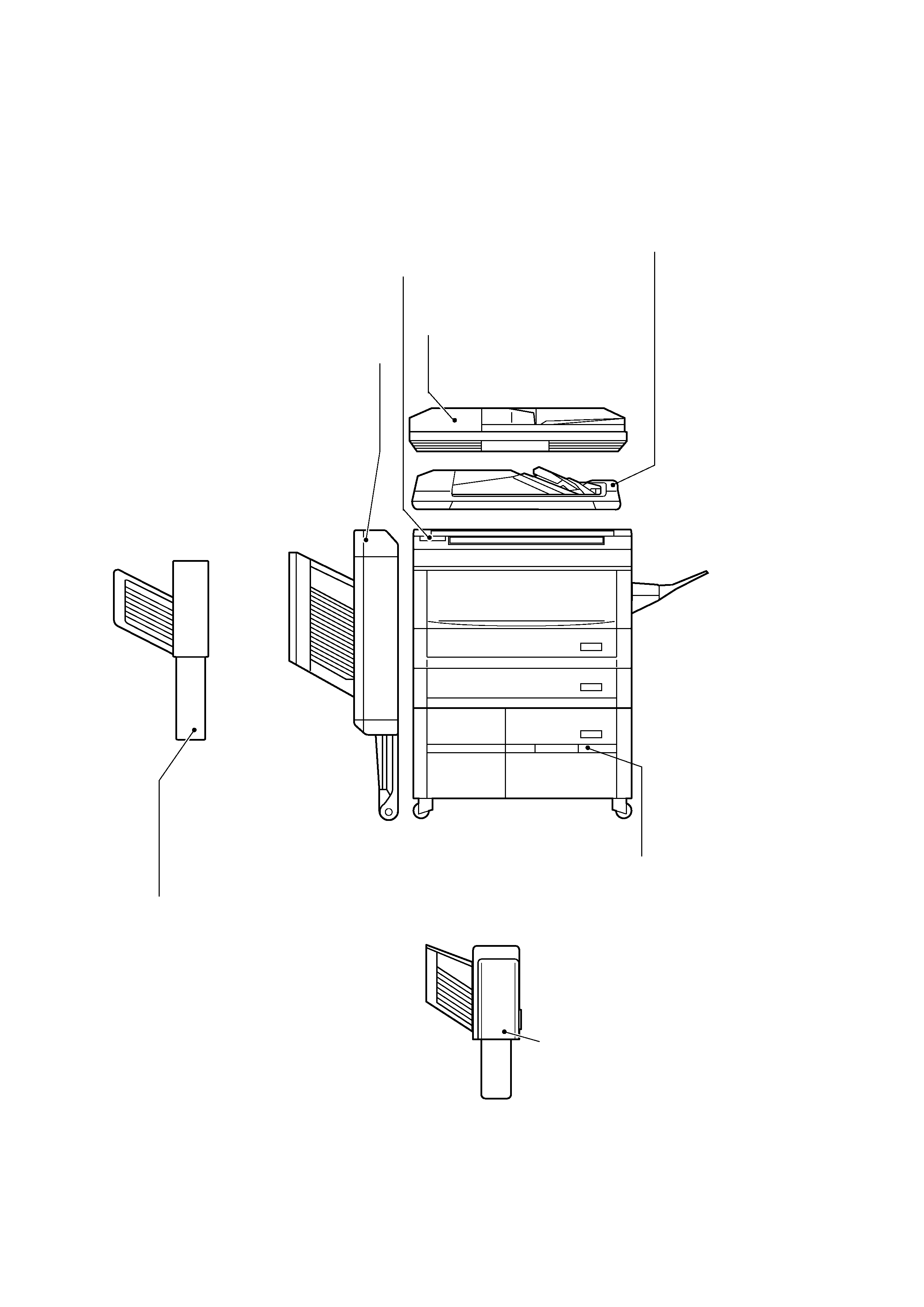
System Configuration
The NP6320 is designed to accommodate the following for fully automated copy work:
ADF-A1
A stack of documents may be placed for
automatic pick-up and feed.
Sorter-A1
Up to 20 copies may be automatically sorted or
grouped by page.
MS-A1
Up to 10 sets of copies may be automatically sorted
or grouped by page.
Stapler Sorter-D3
Up to 10 sets of copies
may be automatically
sorted. Further, copies
may be automatically
sorted and then stapled in
sequence.
Paper Deck Pedestal-J1
Accommodates
as many as 1000
sheets of copy paper.
Control Card V
With the card, the volume of copy work
may be put under control.
ADF-D1
The fastest and easiest way to copy.
Place originals in this feeder and they
are automatically fed to the platen
glass.

COPYRIGHT © 1999 CANON INC.
CANON NP6320 REV.0 DEC. 1999 PRINTED IN JAPAN (IMPRIME AU JAPON)
iii
CONTENTS
CHAPTER 1 GENERAL DESCRIPTION
I.
FEATURES .................................. 1-1
II.
SPECIFICATIONS ....................... 1-2
A.
Type ....................................... 1-2
B.
Construction .......................... 1-2
C.
Performance .......................... 1-3
D.
Others .................................... 1-3
III. NAMES OF PARTS ...................... 1-5
A.
External View ........................ 1-5
B.
Cross Section ........................ 1-6
IV. OPERATION ................................1-7
A.
Control Panel .........................1-7
B.
Setting the Auto Shut-Off
Time ...................................... 1-9
C.
Daily Inspection to Be
Performed by the User .......... 1-9
V.
IMAGE FORMATION
PROCESS ................................. 1-11
A.
Outline ................................ 1-11
CHAPTER 2 BASIC OPERATION
CHAPTER 3 EXPOSURE SYSTEM
I.
BASIC OPERATION .................... 2-1
A.
Functions ............................... 2-1
B.
Outline of Electric Circuitry ... 2-2
C.
Inputs to the DC Controller ... 2-4
D.
DC Controller Outputs ........... 2-7
E.
Basic Sequence of Operations
(Direct, continuous copying, 2
sheets)................................ 2-10
I.
BASIC OPERATION .................... 3-1
A.
Changing the Reproduction
Ratio ...................................... 3-1
II.
LENS DRIVE SYSTEM ................ 3-2
A.
Outline ................................... 3-2
B.
Basic Lens Drive System
Operation (change of
reproduction ratio) ................. 3-4
III. SCANNER DRIVE SYSTEM ....... 3-5
A.
Outline ................................... 3-5
B.
Relation Between Scanner
Sensor and Signals ............... 3-6
C. Basic Scanner Operation ...... 3-7
D.
Scanner Motor Drive System
Operation .............................. 3-8
E.
Scanner Movement for Two-
Page Separation Mode
(copy count 2) .................... 3-10
F.
Document Size
Identification ....................... 3-11
IV. DISASSEMBLY AND
ASSEMBLY ............................... 3-14
A.
Lens Drive Assembly ......... 3-14
B.
Scanner Drive Assembly .... 3-16