REVISION 0
FY8-23B9-000
COPYRIGHT© 2000 CANON INC. 2000 CANON C2050/2020, C2100/2100S REV.0 NOV. 2000 PRINTED IN JAPAN (IMPRIME AU JAPON)
Color image RUNNER
C2050/2020
iR C2100/2100S
NOV. 2000

COPYRIGHT© 2000 CANON INC. 2000 CANON C2050/2020, C2100/2100S REV.0 NOV. 2000 PRINTED IN JAPAN (IMPRIME AU JAPON)
Application
This manual has been issued by Canon Inc. for qualified persons to learn technical
theory, installation, maintenance, and repair of products. This manual covers all
localities where the products are sold. For this reason, there may be information in this
manual that does not apply to your locality.
Corrections
This manual may contain technical inaccuracies or typographical errors due to
improvements or changes in products. When changes occur in applicable products or in
the contents of this manual, Canon will release technical information as the need arises.
In the event of major changes in the contents of this manual over a long or short period,
Canon will issue a new edition of this manual.
The following paragraph does not apply to any countries where such provisions are
inconsistent with local law.
Trademarks
The product names and company names used in this manual are the registered
trademarks of the individual companies.
Copyright
This manual is copyrighted with all rights reserved. Under the copyright laws, this
manual may not be copied, reproduced or translated into another language, in whole or
in part, without the written consent of Canon Inc.
Caution
Use of this manual should be strictly supervised to avoid disclosure of confidential information.
COPYRIGHT © 2000 CANON INC.
Printed in Japan
Imprimé au Japon
i
INTRODUCTION
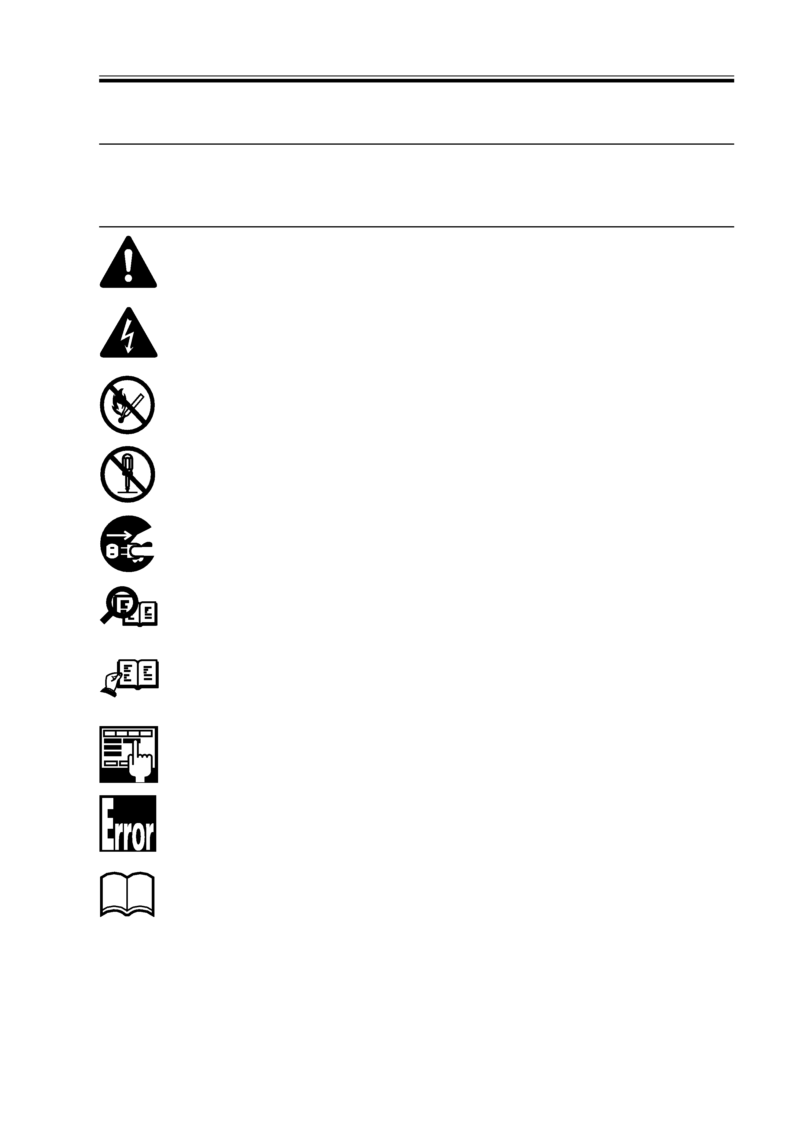
1 Symbols Used
This documentation uses the following symbols to indicate special information:
Symbol
Description
Indicates an item requiring care to avoid combustion (fire).
Indicates an item prohibiting disassembly to avoid electric shocks or problems.
Indicates an item requiring disconnection of the power plug from the electric
outlet.
Indicates an item intended to provide notes assisting the understanding of the
topic in question.
Memo
Indicates an item of reference assisting the understanding of the topic in ques-
tion.
REF.
Provides a description of a service mode.
Provides a description of the nature of an error indication.
Refers to the Copier Basics Series for a better understanding of the contents.
Indicates an item of a non-specific nature, possibly classified as Note, Caution,
or Warning.
Indicates an item requiring care to avoid electric shocks.

ii
INTRODUCTION

iii
CONTENTS
Contents (Reader Unit)
CHAPTER 1 MAINTENANCE AND INSPECTION
1 Variable Resistors, Light-Emitting
Diodes, and Check Pins by PCB ........ 3-6
CHAPTER 3 ARRANGEMENT AND FUNCTIONS
OF ELECTRICAL PARTS
1
2
3
1 Periodically Replaced Parts ................ 1-1
2 Consumables and Durables ................ 1-1
3 Scheduled Servicing ........................... 1-2
4 Scheduled Servicing Chart ................. 1-4
1 Adjusting the Image Position ............. 2-1
1.1
Standards .................................... 2-1
1.2
Checking the Image Position ..... 2-1
2 Making Scanner-Related
Adjustments ........................................ 2-2
2.1
Routing the Scanner Drive
Cable .......................................... 2-2
2.2
Adjusting the Intensity of
the Scanning Lamp .................... 2-3
2.3
After Replacing the Scanning
Lamp .......................................... 2-4
2.4
Mounting Back the Existing
Scanning Lamp .......................... 2-4
2.5
Keeping the Reader Unit
Level ........................................... 2-5
2.6
After Replacing the Standard
White Plate ................................. 2-6
3 Adjusting Other Electrical Parts ......... 2-7
3.1
When Replacing the CCD
Unit ............................................ 2-7
CHAPTER 2 STANDARDS AND ADJUSTMENTS
3.2
When Replacing the Reader
Controller PCB .......................... 2-8
3.3
When Replacing the AP-IP
PCB ............................................ 2-9
3.4
When Replacing the ECO
PCB ............................................ 2-9
3.5
When Replacing the Light
Intensity Detection PCB ............ 2-9
4 Checking the Photointerrupters ........ 2-10
5 Upgrading the Machine .................... 2-12
5.1
Replacing the DIMM ............... 2-12
5.1.1
Removing the DIMM from
the Reader Controller
PCB .................................... 2-13
5.1.2
Mounting the DIMM on the
Reader Controller PCB ...... 2-14
5.2
Downloading ............................ 2-15
5.2.1
Making Preparations .......... 2-15
5.2.2
Downloading Procedure .... 2-15