COPYRIGHT © 1999 CANON INC.
CANON CLC1120/1130/1150 REV.0 MAR. 1999 PRINTED IN JAPAN (IMPRIME AU JAPON)
REVSION 0
MAR. 1999
FY8-13G3-000
COLOR LASER COPIER
1120/1130/1150

COPYRIGHT © 1999 CANON INC.
CANON CLC1120/1130/1150 REV.0 MAR. 1999 PRINTED IN JAPAN (IMPRIME AU JAPON)
IMPORTANT
THIS DOCUMENTATION IS PUBLISHED BY CANON INC., JAPAN, TO SERVE AS A SOURCE
OF REFERENCE FOR WORK IN THE FIELD.
SPECIFICATIONS AND OTHER INFORMATION CONTAINED HEREIN MAY VARY SLIGHTLY
FROM ACTUAL MACHINE VALUES OR THOSE FOUND IN ADVERTISING AND OTHER
PRINTED MATTER.
ANY QUESTIONS REGARDING INFORMATION CONTAINED HEREIN SHOULD BE DIRECTED
TO THE COPIER SERVICE DEPARTMENT OF THE SALES COMPANY.
THIS DOCUMENTATION IS INTENDED FOR ALL SALES AREAS, AND MAY CONTAIN IN-
FORMATION NOT APPLICABLE TO CERTAIN AREAS.
COPYRIGHT © 1999 CANON INC.
Printed in Japan
Imprimé au Japon
Use of this manual should be strictly su-
pervised to avoid disclosure of confidential
information.
Prepared by
OFFICE IMAGING PRODUCTS TECHNICAL SUPPORT DIVISION
CANON INC.
5-1, Hakusan 7-chome, Toride, Ibaraki, 302-8501 Japan

COPYRIGHT © 1999 CANON INC.
CANON CLC1120/1130/1150 REV.0 MAR. 1999 PRINTED IN JAPAN (IMPRIME AU JAPON)
i
INTRODUCTION
This Service Manual contains basic data and figures on the plain paper CLC1120/
1130/1150 needed to service the machine in the field. The copier is designed to enable
fully automated copying work, and may be configured with the following options:
1.
RDF-E2
2.
Stapler Sorter-F1
3.
Film Projector-D1
4.
Paper Deck-E1
For the RDF-E2, Stapler Sorter-F1, and Film Projector-D1, see their respective
Service Manuals for details. This Service Manual covers the copier itself, and consists of
the following chapters:
Chapter 1
General Description introduces the copier's features and specifications,
shows how to operate the printer unit, and explains how copies are made.
Chapter 2
Basic Operation provides outlines of the steps used to generate copies.
Chapter 3
Exposure System discusses the principles of operation used for the
mechanical/electrical operations of the copier's exposure system. It also
explains the timing at which the various units involved are operated, and
shows how they may be disassembled/assembled and adjusted.
Chapter 4
Image Processing System discusses the principles of operation used for
the mechanical/electrical operations of the copier's image processing
system. It also explains the timing at which the various units involved are
operated, and shows how they may be disassembled/assembled and
adjusted.
Chapter 5
Laser Exposure System discusses the principles of operation used for the
mechanical/electrical operations of the copier's laser exposure system. It
also explains the timing at which the various units involved are operated,
and shows how they may be disassembled/assembled and adjusted.
Chapter 6
Image Formation System discusses the principles of how images are
formed. It also explains the timing at which the various units involved in
image formation are operated, and shows how they may be disassembled/
assembled and adjusted.
Chapter 7
Pick-Up/Feeding System discusses the principles of how the printer unit
picks up and moves paper inside it. It also explains the timing at which the
various units involved are operated, and shows how they may be
disassembled/assembled and adjusted.
Chapter 8
Fixing System discusses the principles of how the printer unit fuses toner
images to paper. It also explains the timing at which the various units
involved are operated, and shows how they may be disassembled/
assembled and adjusted.

COPYRIGHT © 1999 CANON INC.
CANON CLC1120/1130/1150 REV.0 MAR. 1999 PRINTED IN JAPAN (IMPRIME AU JAPON)
ii
Chapter 9
Externals/Auxiliary Mechanisms shows the copier's external parts, and
explains the principles used for the copier's various control mechanisms in
view of the functions of electrical and mechanical units and in relation to
their timing of operation. It also shows how these units may be
disassembled/assembled and adjusted.
Chapter 10
Paper Deck discusses the principles of operation used for the series of
operations between pickup and delivery performed by the paper deck. It
also explains the timing at which the various units involved are operated,
and shows how they may be disassembled/assembled and adjusted.
Chapter 11
Installation introduces requirements for the site of installation, and shows
how the printer unit may be installed using step-by-step instructions.
Chapter 12
Maintenance and Servicing provides tables of periodically replaced parts
and consumables/durables and scheduled servicing charts.
Chapter 13
Troubleshooting provides tables of maintenance/inspection, standards/
adjustments, and problem identification (image fault/malfunction).
Appendix contains a general timing chart and general circuit diagrams.
The following rules apply throughout this Service Manual:
1.
Each chapter contains sections explaining the purpose of specific functions
and the relationship between electrical and mechanical systems with
reference to the timing of operation.
In the diagrams,
represents the path of mechanical drive
where a
signal name accompanies the symbol
, the arrow indicates the direction
of the electric signal.
The expression "turn on the power" means flipping on the power switch,
closing the front door, and closing the delivery unit door, which results in
supplying the machine with power.
2.
In the digital circuits, `1' is used to indicate that the voltage level of a given
signal is "High," while `0' is used to indicate "Low." (The voltage value,
however, differs from circuit to circuit.) In addition, the asterisk (*) as in
"DRMD*" indicates that the DRMD signal goes on when `0'.
In practically all cases, the internal mechanisms of a microprocessor cannot
be checked in the field. Therefore, the operations of the microprocessors used
in the machines are not discussed: they are explained in terms of from sensors
to the input of the DC controller PCB and from the output of the DC controller
PCB to the loads.
The descriptions in this Service Manual are subject to change without notice for
product improvement or other purposes, and major changes will be communicated in the
form of Service Information bulletins.
All service persons are expected to have a good understanding of the contents of this
Service Manual and all relevant Service Information bulletins and be able to identify and
isolate faults in the machine.
COPYRIGHT © 1999 CANON INC.
CANON CLC1120/1130/1150 REV.0 MAR. 1999 PRINTED IN JAPAN (IMPRIME AU JAPON)
iii
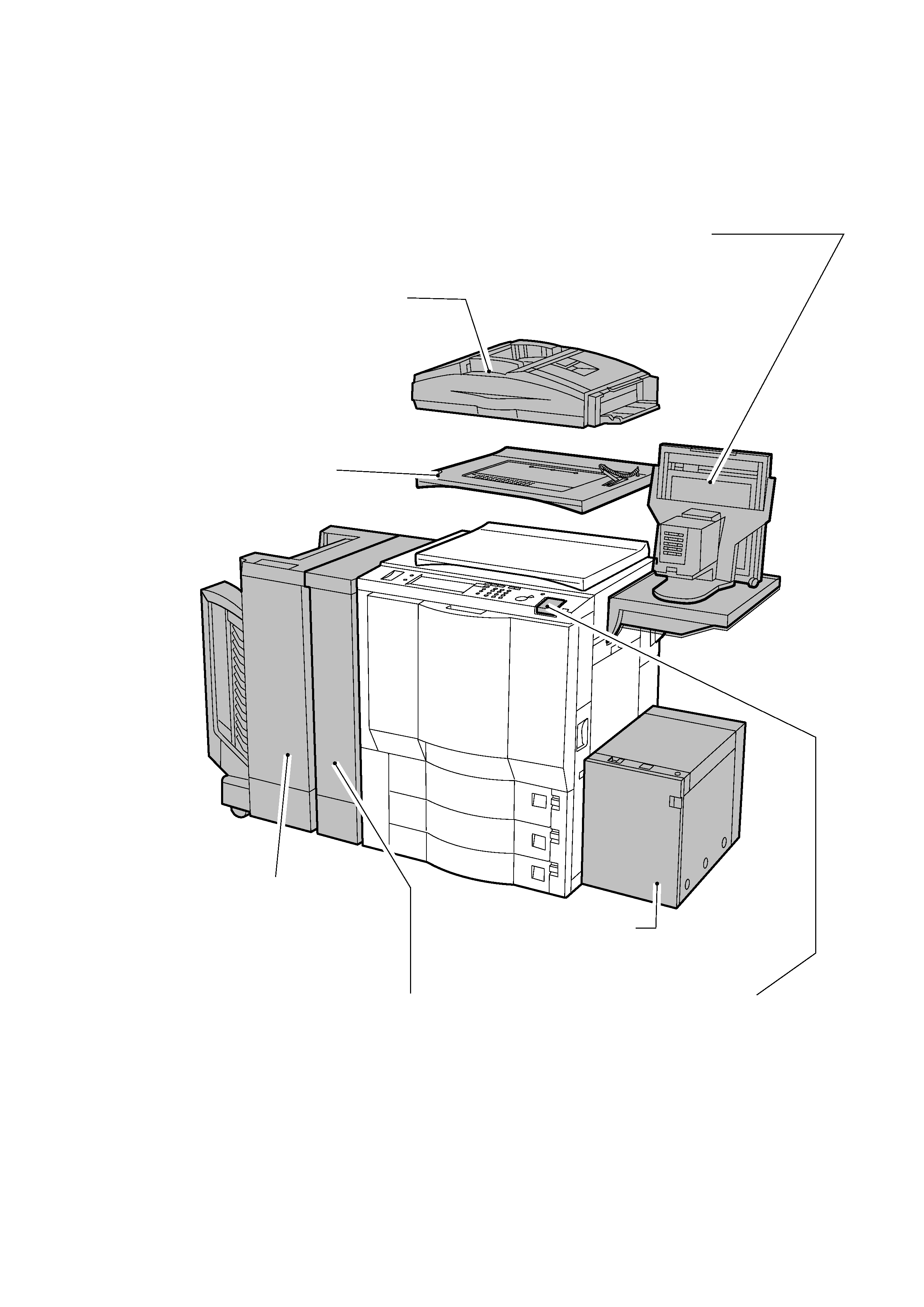
System Configuration
The CLC1120/1130/1150 may be configured as follows to make up a system (the shaded areas
indicate accessories):
The figures above represents the CLC1150; however, the CLC1120/1130 may be configure in
the same way.
CLC1120:
2-cassette model
CLC1130:
3-cassette model
CLC1150:
2-cassette model with a duplexing unit.
RDF-E2
Feeds a large number of originals
automatically for continuous
copying. Accepts double-sided
originals.
CLC Film Projector-D1
Projects 35mm negative or
positive film, large-size negative
film, or transparencies for making
color copies.
Editor-F1
Enables selecting areas and
colors using a point pen.
Stapler Sorter-F1
Sorts or groups copies.
Staples sorted copies.
CLC Buffer Path Unit 1
Limits curling of copied paper.
CLC Paper Deck-E1
Accommodates as many as 2500 sheets of
copy paper (A4/B5/LTR).
Control Card-V
Enables control of copying
work by group.