
ALPINE ELECTRONICS, INC.
Tokyo office: 1-1-8 Nishi Gotanda,
Shinagawa-ku, Tokyo 141-8501, Japan
Tel.: (03) 3494-1101
ALPINE ELECTRONICS OF AMERICA, INC.
19145 Gramercy Place, Torrance,
California 90501, U.S.A.
Tel.: 1-800-ALPINE-1 (1-800-257-4631)
1-888-NAV-HELP (1-888-628-4357)
ALPINE ELECTRONICS OF CANADA, INC.
Suite 203, 7300 Warden Ave. Markham,
Ontario L3R 9Z6, Canada
Tel.: 1-800-ALPINE-1 (1-800-257-4631)
1-888-NAV-HELP (1-888-628-4357)
ALPINE ELECTRONICS OF AUSTRALIA PTY. LTD.
6-8 Fiveways Boulevarde Keysborough,
Victoria 3173, Australia
Tel.: (03) 9769-0000
ALPINE ELECTRONICS GmbH
Kreuzerkamp 7-11
40878 Ratingen, Germany
Tel.: 02102-45 50
ALPINE ITALIA S.p.A.
Via C. Colombo 8, 20090 Trezzano Sul
Naviglio MI, Italy
Tel.: 02-48 47 81
ALPINE ELECTRONICS FRANCE S.A.R.L.
(RCS PONTOISE B 338 101 280)
98, Rue De La Belle Etoile, Z.I. Paris Nord Il
B.P. 50016 F-95945, Roissy,
Charles De Gaulle Cedex, France
Tel.: 01-48 63 89 89
ALPINE ELECTRONICS OF U.K., LTD.
13 Tanners Drive, Blakelands,
Milton Keynes MK14 5BU, U.K.
Tel.: 01908-61 15 56
ALPINE ELECTRONICS DE ESPAÑA, S.A.
Portal De Gamarra 36, Pabellón 32
01013 Vitoria (Alava)-Apdo. 133, Spain
Tel.: 34-45-283588
Designed by ALPINE Japan
Printed in Japan (Y)
68P30540Y46-O
Yamagata Printing
Co., Ltd.
2-6-34, Takashima,
Nishi-ku, Yokohama,
Kanagawa, Japan
R
R
NVE-N077P
Guide for Installation and Connections
Guide d'installation et de connexion
Guía de instalación y conexiones
Installations- und Anschlußanleitung
Guida all'installazione e al collegamento
Handleiding voor installatie en aansluiting Nederlands
Italiano
Deutsch
Español
Français
English
Voice Navigation System
2
PRECAUTIONS
s GUIIDE FOR INSTALLATION AND CONNECTIONS
FOR AUTHORIZED ALPINE DEALERS
· Please read this GUIDE FOR INSTALLATION
AND CONNECTIONS FOR AUTHORIZED
ALPINE DEALERS and the OWNER'S MANUAL
thoroughly to familiarize yourself with each control
and function. We at ALPINE hope that your new
NVE-N077P will give you many years of
enjoyment.
In case of problems when installing your unit, please
contact your authorized ALPINE dealer.
Points to Observe for Safe Usage
· For safe operation of this system, please read this
manual carefully. We cannot be responsible for
problems resulting from failure to observe the
instructions in this manual.
· Pictorial displays are used to point out safety tips
to prevent harm to yourself or others and property
damage. Here is what these pictorial displays
mean. Knowing them is important to understand
this manual.
· Meaning of displays
BEFORE WIRING, DISCONNECT THE CABLE
FROM THE NEGATIVE BATTERY TERMINAL.
Failure to do so may result in electric shock or injury
due to electrical shorts.
DO NOT ALLOW CABLES TO BECOME ENTAN-
GLED IN SURROUNDING OBJECTS. Arrange
wiring and cables in compliance with the manual to
prevent obstructions when driving. Cables or wiring
that obstruct or hang up on places such as the
steering wheel, shift lever, brake pedals, etc. can be
extremely hazardous.
DO NOT SPLICE INTO ELECTRICAL CABLES.
Never cut away cable insulation to supply power to
other equipment. Doing so will exceed the current
carrying capacity of the wire and result in fire or
electric shock.
DO NOT INSTALL IN LOCATIONS WHICH MIGHT
HINDER VEHICLE OPERATION, SUCH AS THE
STEERING WHEEL OR SHIFT LEVER. Doing so
may obstruct forward vision or hamper movement
etc. and results in serious accident.
DO NOT DAMAGE PIPE OR WIRING WHEN
DRILLING HOLES. When drilling holes in the
chassis for installation, take precautions so as not to
contact, damage or obstruct pipes, fuel lines, tanks
or electrical wiring. Failure to take such precautions
may result in fire.
DO NOT USE BOLTS OR NUTS IN THE BRAKE
OR STEERING SYSTEMS TO MAKE GROUND
CONNECTIONS. Bolts or nuts used for the brake or
steering systems (or any other safety-related sys-
tem), or tanks should NEVER be used for installa-
tions or ground connections. Using such parts could
disable control of the vehicle and cause fire etc.
DO NOT INSTALL THE MONITOR NEAR THE
PASSENGER SEAT AIR BAG. If the unit is not
installed correctly the air bag may not function
correctly and when triggered the air bag may cause
the monitor to spring upwards causing an accident
and injuries.
MAKE THE CORRECT CONNECTIONS. Failure to
make the proper connections may result in fire or
product damage.
Warning
Warning
Caution
DO NOT DISASSEMBLE OR ALTER. Doing so may
result in an accident, fire or electric shock.
KEEP SMALL OBJECTS SUCH AS BATTERY OUT
OF THE REACH OF CHILDREN. Swallowing them
may result in serious injury. If swallowed, consult a
physician immediately.
USE THE CORRECT AMPERE RATING WHEN
REPLACING FUSES. Failure to do so may result in
fire or electric shock.
USE ONLY IN CARS WITH A 12 VOLT NEGATIVE
GROUND. (Check with your dealer if you are not
sure.) Failure to do so may result in fire, etc.
This symbol means important
instructions. Failure to heed them
can result in injury or material
property damage.
This symbol means important
instructions. Failure to heed them
can result in serious injury or
death.

3
Precautions
IMPORTANT
Please record the serial number of your unit in the
space provided on the back cover of Owner's
Manual and keep it as a permanent record. The
serial number plate is located on the bottom of the
unit.
· For installation of the main unit, avoid areas with a
high incidence of dust or moisture. Installing the
unit in such locations may result in contamination
of the DVD ROM making it unreadable.
· Do not install the navigation system near a CD
player that may interfere with GPS signal
reception.
· The optimum locations for instaling the GPS aerial
are:
on the dashboard where no metal piece (such
as the defogger wire or aerial wire) is located on
the windshield.
where no metal cover is located.
· Route the Speed Pulse Sensor cable away from
the audio cables in order to avoid picking up
noises.
Caution
ARRANGE THE WIRING SO IT IS NOT CRIMPED
OR PINCHED BY A SHARP METAL EDGE. Route
the cables and wiring away from moving parts (like
the seat rails) or sharp or pointed edges. This will
prevent crimping and damage to the wiring. If wiring
passes through a hole in metal, use a rubber grom-
met to prevent the wire's insulation from being cut by
the metal edge of the hole.
HAVE THE WIRING AND INSTALLATION DONE
BY EXPERTS. The wiring and installation of this unit
requires special technical skill and experience. To
ensure safety, always contact the dealer where you
purchased this product to have the work done.
USE SPECIFIED ACCESSORY PARTS AND
INSTALL THEM SECURELY. Be sure to use only
the specified accessory parts. Use of other than
designated parts may damage this unit internally or
may not securely install the unit in place. This may
cause parts to become loose resulting in hazards or
product failure.
DO NOT INSTALL IN LOCATIONS WITH HIGH
MOISTURE OR DUST. Avoid installing the unit in
locations with high incidence of moisture or dust.
Moisture or dust that penetrates into this unit may
result in product failure.

4
PRECAUTIONS
2
1. Preparation
5
2. Connections
6
3-1. NVE-N077P Wiring Diagram With TME-M750
7
3-2. NVE-N077P Wiring Diagram With IVA-C800R/IVA-M700R/
CVA-1005R
8
3-3. NVE-N077P Wiring Diagram With CVA-1000R
9
3. Mounting
12
4. Confirmation
14
3-4. NVE-N077P Wiring Diagram With TME-M006SP/TME-M005P 10
Contents
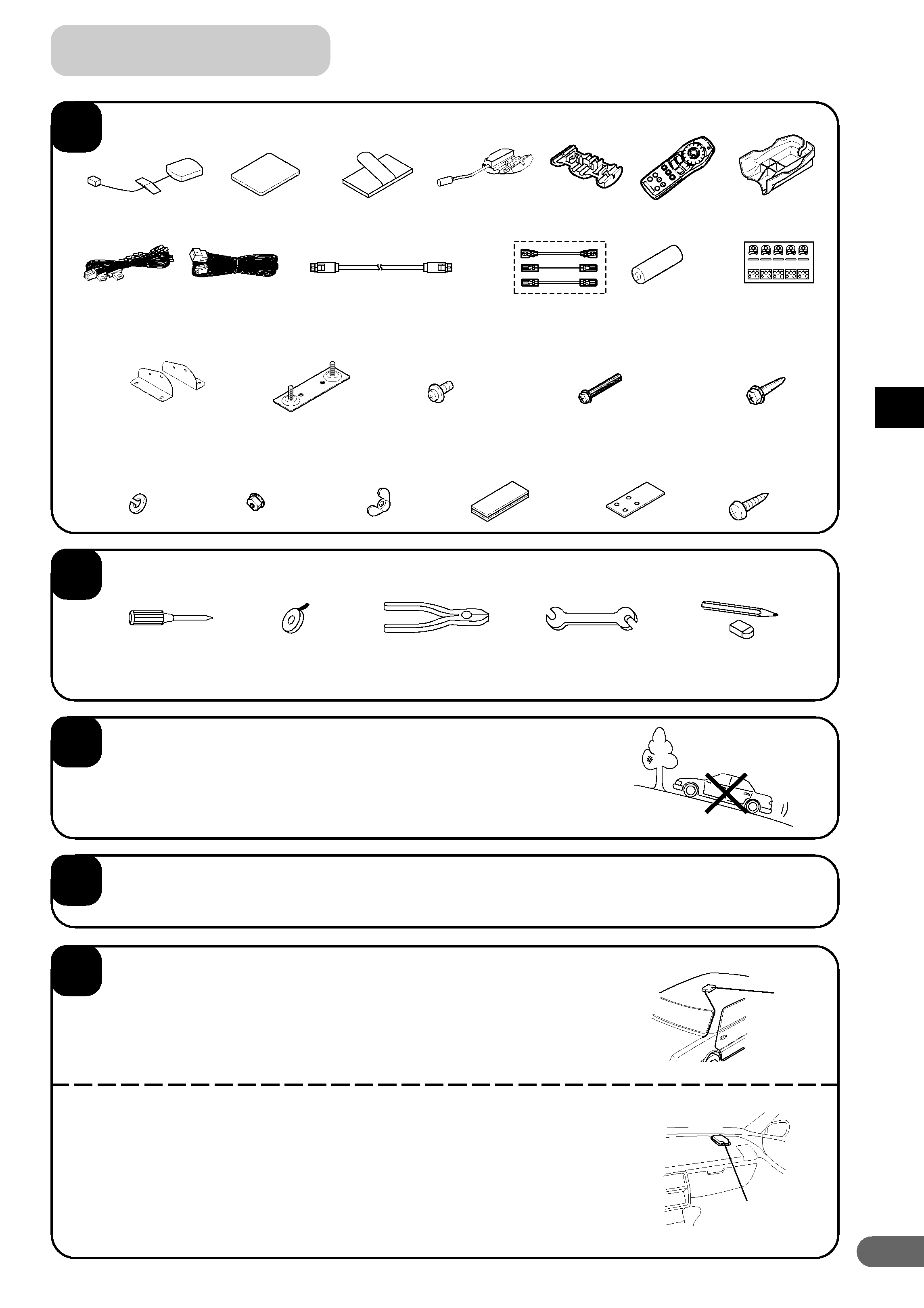
5
Check accessory parts.
× 3
× 2
Prepare tools and mounting information.
Screwdriver
Pencil and eraser
Spanner
Pliers
Electrical tape
Park the vehicle in a safe and level location.
Apply the brake and remove the ignition key.
Mount the aerial on the roof.
Clean dust and oil at the mounting location and mount the aerial.
Notes:
· The magnet of the aerial is very strong. Proceed cautiously to prevent any
damage to the vehicle's body. Keep the magnet away from articles susceptible
to magnetic fields such as credit cards, watches, etc.
· Do not paint the aerial. Reception sensitivity may be decreased.
Mounting the aerial inside the vehicle.
1. Clean the mounting location.
2. Put on the aerial mounting plate.
3. Mount the aerial.
Notes:
· Mount the aerial on a flat plane of the dash board or rear tray.
· Some thermal reflection type or thermal absorption type glass may interrupt
high frequency waves. If reception is poor with the aerial installed inside the
car, try to mount the aerial outside the car.
Aerial
Aerial
1. Preparation
1
2
3
4
5
Power cables
13P RGB extension cable (6 m)
Remote control
stickers
1 Bracket
5 Flanged self-tapping
screw (M5
× 15)
4 Hex bolt (M6
× 50)
3 Screw with double
washer (M5
× 8)
2 Floor base
One each for left and right
6 Spring
washer (M6)
7 Flanged hex
nut (M6)
8 Wing nut (M6)
9 Velcro
fastener
" Self-tapping
screw (M4
× 12)
! Velcro tape
× 2
× 4
× 4
× 4
× 4
× 4
× 4
× 2
× 4
× 2
Battery (AA)
ZOOM
UNGEB.
EIN
AUS
ROUTE
POS.
ZIEL
EING.
MENU
ZURUCK
STIMM
ZOOM
UNGEB.
EIN
AUS
ROUTE
POS.
ZIEL
EING.
MENU
ZURUCK
STIMM
ZOOM
UNGEB.
EIN
AUS
ROUTE
POS.
ZIEL
EING.
MENU
ZURUCK
STIMM
ZOOM
UNGEB.
EIN
AUS
ROUTE
POS.
ZIEL
EING.
MENU
ZURUCK
STIMM
ZOOM
UNGEB.
EIN
AUS
ROUTE
POS.
ZIEL
EING.
MENU
ZURUCK
STIMM
Extension
cables
Remote control
holder
Remote
control
Solderless
connector
Parking brake
aux. cord
Cable clamper
Aerial
mounting plate
GPS aerial