En
COMPACT DISC STEREO SYSTEM
SISTEMA ESTEREO CON REPRODUCTOR DE DISCOS COMPACTOS
CHAINE STEREO AVEC LECTEUR DE DISQUES COMPACTS
Z-A60
OPERATING INSTRUCTIONS
MANUAL DE INSTRUCCIONES
MODE D'EMPLOI
En (English)
E (Español)
8C-MA5-901-01
0200420AMO-U-S
F (Français)
U
Visit us on the Internet at
Consultez notre site Internet
www.aiwa.com
Call Toll Free
Appel gratuit
1-800-BUY-AIWA
FOR ASSISTANCE AND INFORMATION
POUR L'ASSISTANCE ET LES INFORMATIONS
2 ENGLISH
ENGLISH
IMPORTANT SAFETY INSTRUCTIONS
Read the Operating Instructions carefully and completely before
operating the unit. Be sure to keep the Operating Instructions for
future reference. All warnings and cautions in the Operating
Instructions and on the unit should be strictly followed, as well
as the safety suggestions below.
Warning
To prevent electric shock or injury, these safety instructions should
be followed in the installation, use and servicing the unit.
Installation
Attachments - Do not use attachments not recommended by
the unit manufacturer as they may result in the risk of fire, electric
shock or injury to persons.
Water and Moisture - Do not use this unit near water - for
example, near a bathtub, washbowl, kitchen sink, or laundry tub,
in a wet basement, or near a swimming pool, and the like.
WARNING
TO REDUCE THE RISK OF FIRE OR ELECTRIC
SHOCK, DO NOT EXPOSE THIS APPLIANCE TO
RAIN OR MOISTURE.
"CAUTION:TO REDUCE THE RISK OF
ELECTRIC SHOCK,
DO NOT REMOVE COVER (OR BACK).
NO USER-SERVICEABLE PARTS INSIDE.
REFER SERVICING TO QUALIFIED
SERVICE PERSONNEL."
CAUTION
RISK OF ELECTRIC SHOCK
DO NOT OPEN
Explanation of Graphical Symbols:
The lightning flash with arrowhead symbol,
within an equilateral triangle, is intended to alert
the user to the presence of uninsulated
"dangerous voltage" within the product's
enclosure that may be of sufficient magnitude
to constitute a risk of electric shock to persons.
The exclamation point within an equilateral
triangle is intended to alert the user to the
presence
of
important
operating
and
maintenance (servicing) instructions in the
literature accompanying the appliance.
Owner's record
For your convenience, record the model number and serial
number (you will find them on the rear of your unit) in the space
provided below. Please refer to them when you contact your Aiwa
dealer in case of difficulty.
Model No.
Serial No. (Lot No.)
CX-ZA60
SX-ZA60
Heat - Do not use this unit near sources of heat, including heating
vents, stoves, or other appliances that generate heat. It also
should not be placed in temperatures less than 5°C (41°F) or
greater than 35°C (95°F ).
Mounting surface - Place the unit on a flat, even surface.
Accessories - Do not place this unit on an unstable cart, stand,
tripod, bracket, or table. The unit may fall, causing serious injury
to a child or an adult, and serious damage to the appliance. Use
only with a cart, stand, tripod, bracket, or table recommended by
the manufacturer, or sold with the unit. Any mounting of the
appliance should follow the manufacturer's instructions, and
should use a mounting accessory recommended by the
manufacturer.
Portable cart - An appliance and cart
combination should be moved with care. Quick
stops, excessive force, and uneven surfaces may
cause the appliance and cart combination to
overturn.
Ventilation - The unit should be situated with adequate space
around it so that proper heat ventilation is assured. Allow 10 cm
clearance from the rear and the top of the unit, and 5 cm from
the each side.
Slots and openings in the cabinet and the back or bottom are
provided for ventilation, and to ensure reliable operation of the
unit and to protect it from overheating, these openings must not
be blocked or covered. The openings should never be blocked
by placing the unit on a bed, sofa, rug or other similar surface.
This unit should not be placed in a built-in installation such as a
bookcase unless proper ventilation is provided.
Object and Liquid Entry - Never push objects of any kind into
this unit through the cabinet slots as they may touch dangerous
voltage points or short-circuit parts that could result in a fire or
electric shock. Never spill liquid of any kind on the unit.
Electric Power
Power Sources - This unit should be operated only from the
type of power source indicated on the marking label. If you are
not sure of the type of power supply to your home, consult your
appliance dealer or local power company. To operate unit on
battery power, or other sources, refer to the operating instructions.
Grounding or Polarization - This unit is provided with a polarized
alternating-current line plug (a plug having one blade wider than
the other). This plug will fit into the power outlet only one way.
This is a safety feature. If you are unable to insert the plug fully
into the outlet, try reversing the plug. If the plug should still fail to
fit, contact your electrician to replace your obsolete outlet. Do
not defeat the safety purpose of the polarized plug.
Power-Cord Protection - Power-supply cords should be routed
so that they are not likely to be walked on or pinched by items
placed upon or against them, paying particular attention to cords
at plugs, convenience receptacles, and the point where they exit
from the product.
Overloading - Do not overload wall outlets, extension cords,
integral convenience receptacles as this can result in a risk of
fire or electric shock.
ENGLISH
3
En
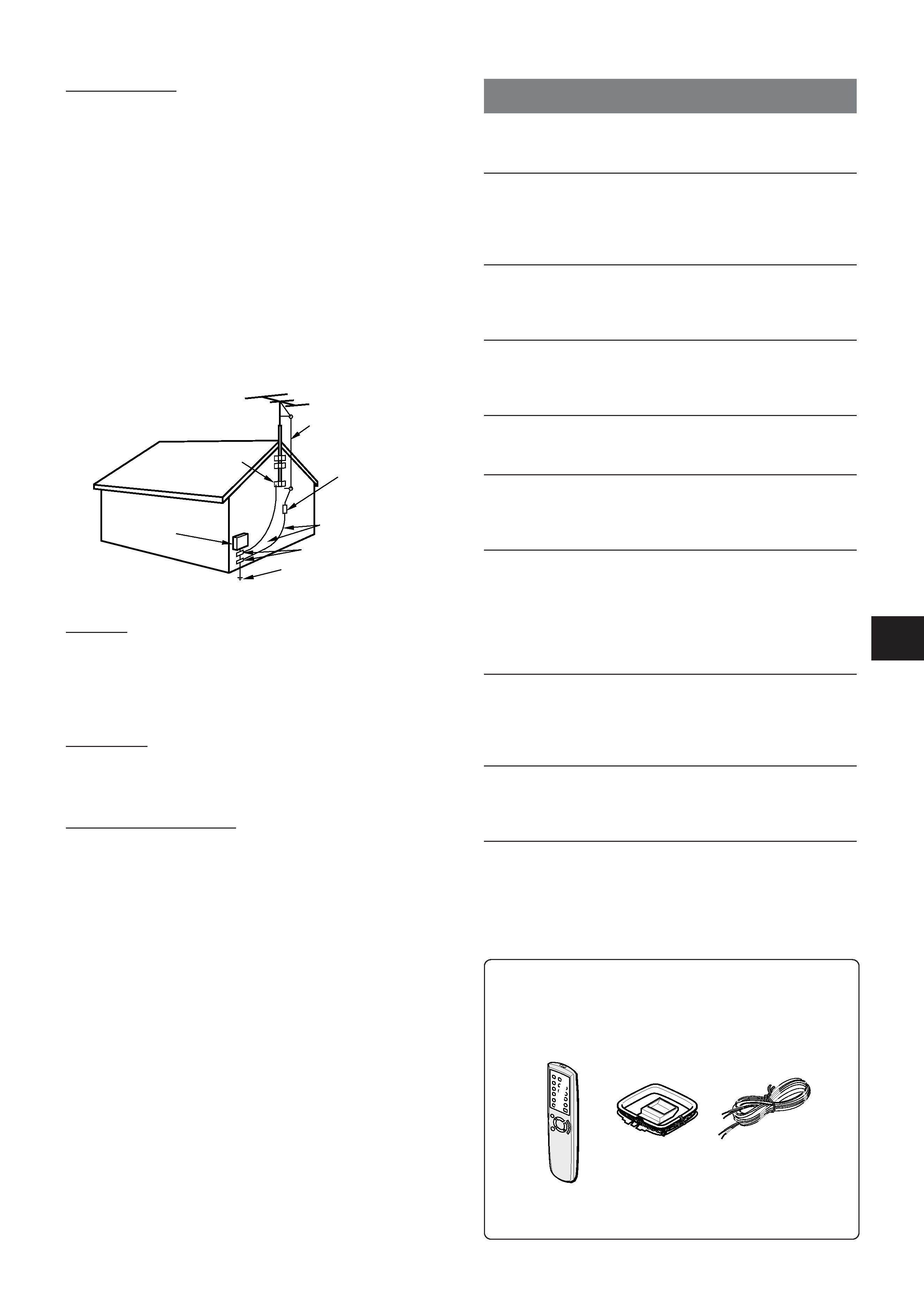
Operating Instructions, etc.
Check your system and accessories
CX-ZA60 Compact disc stereo cassette receiver
SX-ZA60 Front speakers
Remote Control
FM antenna
AM antenna
TABLE OF CONTENTS
PREPARATIONS
CONNECTIONS ...............................................................
4
REMOTE CONTROL ........................................................
5
BEFORE OPERATION .....................................................
5
SOUND
AUDIO ADJUSTMENTS ..................................................
7
GRAPHIC EQUALIZER ....................................................
7
RADIO RECEPTION
MANUAL TUNING ............................................................
8
PRESETTING STATIONS ................................................
9
TAPE PLAYBACK
BASIC OPERATIONS ......................................................
9
CD PLAYING
BASIC OPERATIONS ...................................................... 10
PROGRAMMED PLAY ..................................................... 11
RECORDING
BASIC RECORDING ........................................................ 11
DUBBING ......................................................................... 12
DUBBING THE WHOLE TAPE ......................................... 12
AI EDIT RECORDING ...................................................... 13
PROGRAMMED EDIT RECORDING ............................... 14
CLOCK AND TIMER
SETTING THE CLOCK ..................................................... 15
SETTING THE SLEEP TIMER ......................................... 15
SETTING THE TIMER ...................................................... 16
OTHER CONNECTIONS
CONNECTING OPTIONAL EQUIPMENT ....................... 17
LISTENING TO EXTERNAL SOURCES ......................... 17
GENERAL
CARE AND MAINTENANCE ........................................... 18
TROUBLESHOOTING GUIDE ......................................... 18
SPECIFICATIONS ............................................................ 19
PARTS INDEX ...................................................
Back cover
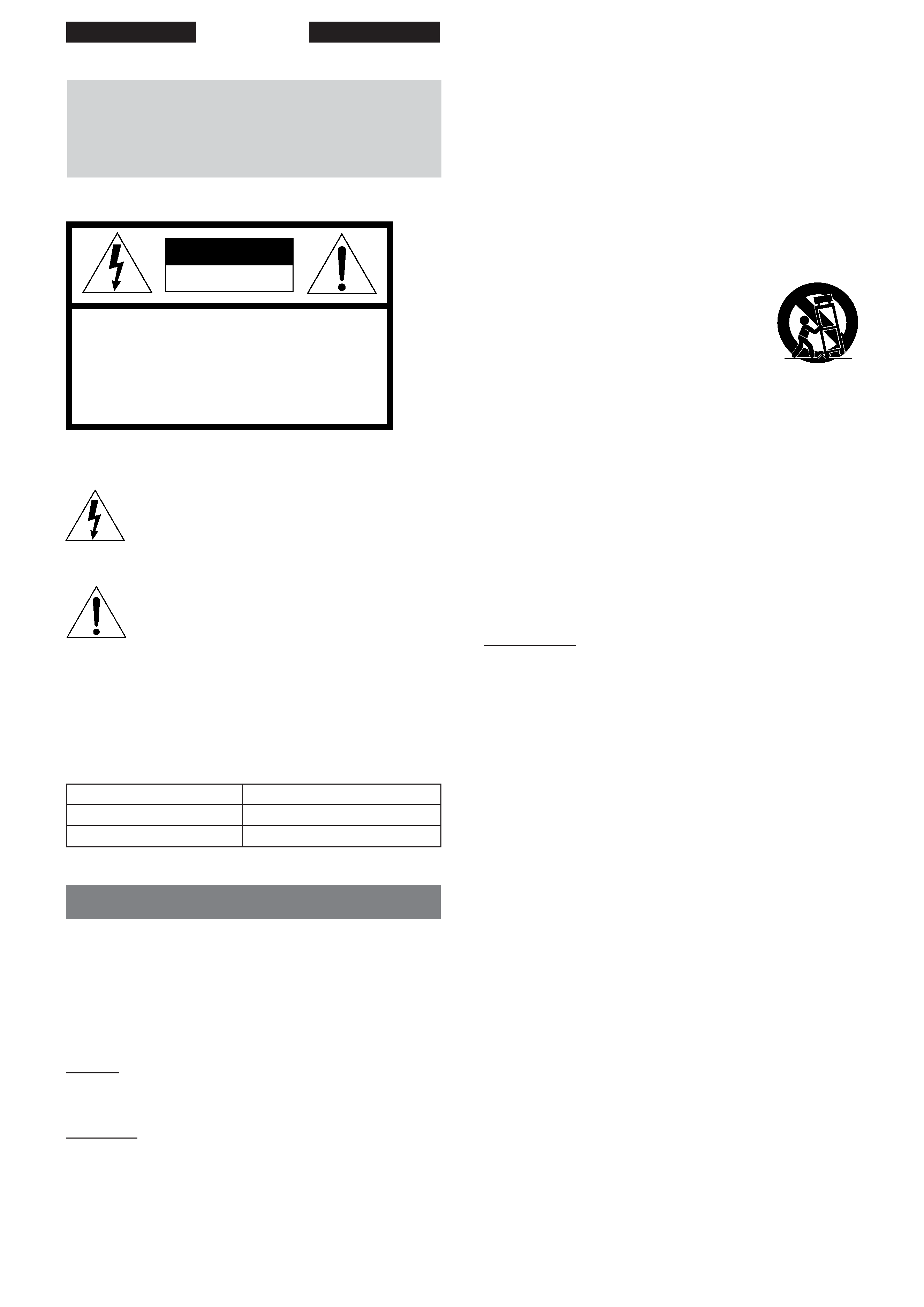
Outdoor Antenna
Power lines - An outside antenna system should not be located
in the vicinity of overhead power lines or other electric light or
power circuits, or where it can fall into such power lines or circuits.
When installing an outside antenna system, extreme care should
be taken to keep from touching such power lines or circuits as
contact with them might be fatal.
Outdoor Antenna Grounding - If an outside antenna or cable
system is connected to the unit, be sure the antenna or cable
system is grounded so as to provide some protection against
voltage surges and built-up static charges. Section 810 of the
National Electrical Code, ANSI/NFPA No.70, provides information
with regard to proper grounding of the mast and supporting
structure, grounding of the lead-in wire to an antenna discharge
unit, size of grounding conductors, location of antenna-discharge
unit, connection to grounding electrodes, and requirements for
the grounding electrode. See the figure.
ANTENNA LEAD IN WIRE
ANTENNA DISCHARGE
UNIT
(NEC SECTION 810-20)
GROUNDING
CONDUCTORS
(NEC SECTION 810-21)
GROUND CLAMPS
POWER SERVICE GROUNDING
ELECTRODE SYSTEM
(NEC ART 250 PART H)
NEC-NATIONAL ELECTRICAL CODE
ELECTRIC
SERVICE
EQUIPMENT
GROUND CLAMP
Antenna Grounding According to the National Electrical Cord
Lightning
For added protection for this unit receiver during a lightning storm,
or when it is left unattended and unused for long periods of time,
unplug it from the wall outlet and disconnect the antenna or cable
system. This will prevent damage to the unit due to lightning and
powerline surges.
Maintenance
Cleaning - Unplug this unit from the wall outlet before cleaning.
Do not use liquid cleaners or aerosol cleaners. Use a damp cloth
for cleaning.
Damage Requiring Service
Unplug this unit from the wall outlet and refer servicing to qualified
service personnel under the following conditions:
- When the power cord or plug is damaged.
- If liquid has been spilled, or objects have fallen into the unit.
- If the unit has been exposed to rain or water.
- If the unit does not operate normally by following the operating
instructions. Adjust only those controls that are covered by the
operating instructions as improper adjustment of other controls
may result in damage and will often require extensive work by
a qualified technician to restore the unit to normal operation.
- If the unit has been dropped or the cabinet has been damaged.
- When the unit exhibits a distinct change in performance - this
indicates a need for service.
Do not attempt to service this unit yourself as opening or removing
covers may expose you to dangerous voltage or other hazards.
Refer all servicing to qualified service personnel.
Replacement Parts - When replacement parts are required, be
sure the service technician has used replacement parts specified
by the manufacturer or having the same characteristics as the
original part. Unauthorized substitutions may result in fire, electric
shock or other hazards.
Safety Check - Upon the completion of any service or repairs to
this unit, ask the service technician to perform safety checks to
determine that the unit is in proper operating condition.
4 ENGLISH
PREPARATIONS
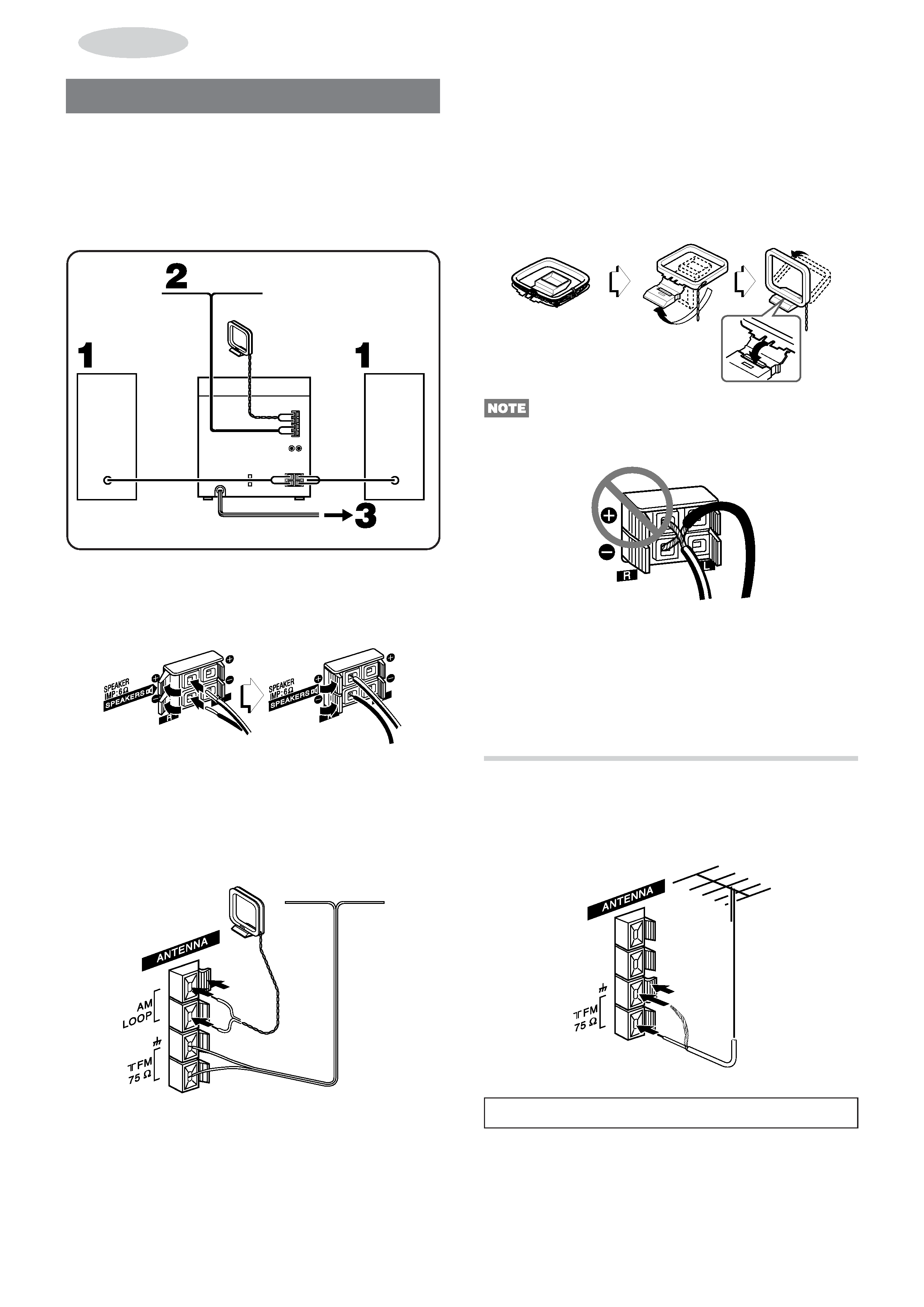
CONNECTIONS
IMPORTANT
Connect the speakers, antennas and all optional equipment first.
Then connect the AC cord.
There are no difference between the front speakers. Both
speakers can be connected as L (left) or R (right).
FM antenna
AM antenna
Left
speaker
Right
speaker
Speaker
cord
AC cord
1 Connect the right and left speakers to the main
unit.
Connect the right speaker cord to SPEAKERS R terminals,
and left to SPEAKERS L terminals.
The speaker cord with the white stripe should be connected
to 0 terminal and the black cord to 9 terminal.
2 Connect the supplied antennas.
Connect the FM antenna to FM 75 terminals and the AM
antenna to AM LOOP terminals.
3 Connect the AC cord to an AC outlet.
· The Demo will begin when the AC cord is plugged into an
AC outlet. See page 6 "DEMO" for details.
AM antenna
FM antenna
To position the antennas
FM antenna:
Extend the antenna horizontally in a T-shape and fix its ends to
the wall.
AM antenna:
Position to find the best reception.
To stand the AM antenna on a surface
Fix the claw to the slot.
· Be sure to connect the speaker cords correctly. Improper
connections can cause short circuits in SPEAKERS terminals.
· Do not leave objects generating magnetism, such as credit
cards, near the speakers, as the objects may be damaged.
· Do not bring the FM antenna near metal objects or curtain rails.
· Do not bring the AM antenna near other optional equipment,
the stereo system itself, the AC cord or speaker cords, since
noise will be picked up.
· Do not unwind the AM antenna wire.
CONNECTING AN OUTDOOR ANTENNA
For better FM reception, use of an outdoor antenna is
recommended.
Connect the outdoor antenna to FM 75 terminals.
To connect other optional equipment page 17.
ENGLISH
5
En
PREP
ARA
TIONS
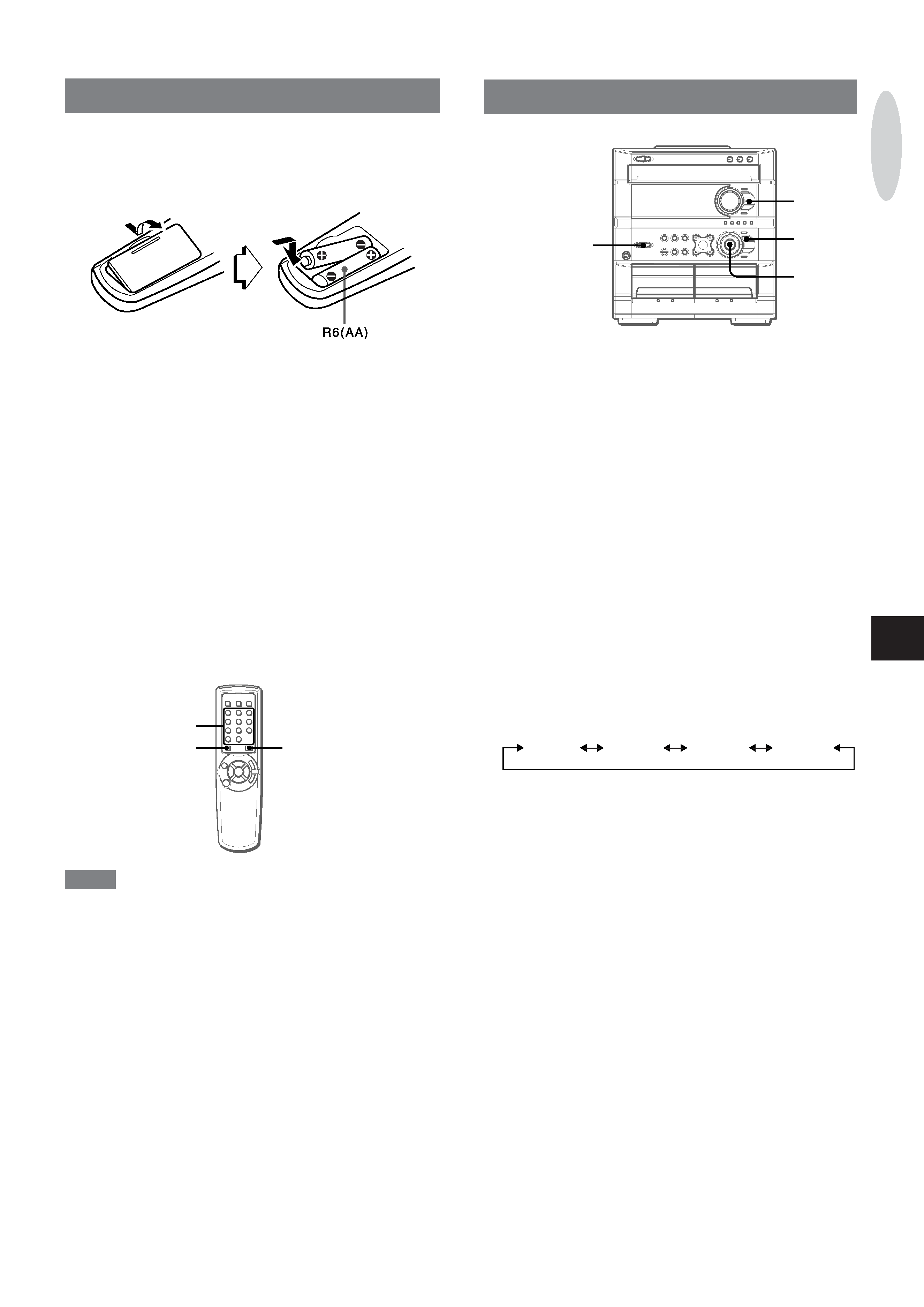
REMOTE CONTROL
Inserting batteries
Detach the battery cover on the rear of the remote control and
insert two R6 (size AA) batteries.
When to replace the batteries
The maximum operational distance between the remote control
and the sensor on the main unit should be approximately 5 meters
(16 feet). When this distance decreases, replace the batteries
with new ones.
To use SHIFT on the remote control
Buttons 1 have two different functions. One of these functions
is indicated on the button, and the other on the plate above the
button.
To use the function on the button, simply press the button.
To use the function on the plate above the button, press the button
while pressing SHIFT.
To use FUNCTION on the remote control
FUNCTION substitutes for the function buttons (TAPE/DECK 1/2,
TUNER/BAND, VIDEO/AUX/PHONO, CD) on the main unit.
Each time FUNCTION is pressed, the next function is selected
cyclically.
1
SHIFT
FUNCTION
NOTE
· If the remote control is not going to be used for an extended
period of time, remove the batteries to prevent possible
electrolyte leakage.
· The remote control may not operate correctly when:
- The line of sight between the remote control and the remote
sensor inside the display window is exposed to intense light,
such as direct sunlight.
- Other remote controls are used nearby (those of a television,
etc.).
BEFORE OPERATION
POWER
6 STANDBY/ON
ECO
MULTI
JOG
ENTER
To turn the power on
Press one of the function buttons (TAPE/DECK 1/2, TUNER/
BAND, VIDEO/AUX/PHONO or CD).
Playback of the inserted disc or tape begins, or the previously
tuned station is received (Direct Play Function).
POWER is also available.
When the unit is turned on, the disc compartment may open and
close to reset the unit.
To turn the power off
Press POWER 6 STANDBY/ON
Illumination guides
Whenever POWER or one of the function buttons is pressed,
the buttons for the selected operation light up or flash.
Example: When CLOCK is pressed, aSET, f and g light
up as a guide to setting the current time.
To change the brightness level of the display
1 Press ECO twice so that "DIM MODE" is displayed.
2 Within 4 seconds, press ENTER.
3 Within 4 seconds, turn MULTI JOG to select the dimmer mode
as below.
DIM-OFF
DIMMER 1
DIMMER 2
DIMMER 3
"DIM OFF" mode is the brightest and "DIMMER 3" mode is
the dimmest.
In "DIMMER 3" mode, the spectrum analyzer, and the button
illumination light off in addition.
4 Within 4 seconds, press ENTER to set the selected mode.