SERVICE MANUAL
DA
TA
XR-M200
XR-M201
XRM200
RCAAT11
SYSTEM
TYPE
REMOTE
CONTROLLER
COMPACT DISC
STEREO SYSTEM
BASIC TAPE MECHANISM : 2ZM-1 YR9NC / YR11NC
BASIC CD MECHANISM : 3ZG-3 E3NC
LH, U, K, G,
HA, HR, HS
EZ
S/M Code No. 09-006-425-1R1
REVISION
· This Service Manual is the "Revision Publishing" and replaces "Simple Manual"
XR-M200 <LH,U,K,HA,HR,HS> / XR-M201 <EZ> (S/M Code No. 09-004-425-1T1).
· This Service Manual does not include "TAPE MECHANISM EXPLODED VIEW &
PARTS LIST" for 2ZM-1 YR11NC. This items will be issued in the next Supplement.
TAPE
MECHANISM
CD
MECHANISM
XRM200
XRM201
3ZG3
E3NC
LH, U, K, HA,
HR, HS
G
EZ
2ZM1
YR9NC
2ZM1
YR11NC
2ZM1
YR9NC

2
Inputs
VIDEO/AUX: 0.4 V
MD: 0.4 V
Outputs
LINE OUT: 0.4 V (47 kohms load)
SPEAKERS HIGH FREQ:
accepts speakers of 16 ohms or more
SPEAKERS LOW FREQ:
accepts speakers of 6 ohms or more
PHONES (stereo minijack): accepts
headphones of 32 ohms or more
<Cassette deck section>
Track format
4 tracks, 2 channels stereo
Frequency response
CrO
2 tape: 50 Hz 16000 Hz
Normal tape: 50 Hz 15000 Hz
Signal-to-noise ratio
50 dB
(CrO
2 tape peak level above 1 kHz)
Recording system
AC bias
Heads
Recording/playback head x 1
Erase head x 1
<Compact disc player section>
Laser
Semiconductor laser (
=780 nm)
D/A converter
1 bit dual
Signal-to-noise ratio
75 dB (1 kHz, 0 dB)
Harmonic distortion
0.1 % (1 kHz, 0 dB)
Wow and flutter
Unmeasurable
<General>
Power requirements
LH,HA,HR: AC : 120 V/220 V 240 V,
switchable 50/60 Hz
U:
AC : 120 V, 60 Hz
EZ,K,HS,G: AC : 230 V, 50 Hz
Power consumption
LH,HA,HR: 95 W
U:
80 W
EZ,K,HS,G: 90 W
Dimensions of main unit
175 x 260 x 299 mm
(W x H x D)
(7 x 101/
4 x 11
7/
8 in.)
Weight of main unit
5.5 kg (12 lbs 2 oz)
Standby power consumption If the power-economizing mode is on:
1.0 W
If the power-economizing mode is off:
LH,HA,HR,EZ,K,HS,G:
13 W
U:
12 W
Speaker system
Cabinet type
3 way, built in subwoofer
(magnetic shield type)
Speakers
Subwoofer:
130 mm (51/
8 in.) cone type
Full range:
100 mm (4 in.) cone type
Super tweeter:
20 mm (13/
16 in.) ceramic type
Impedance
6 ohms / 16 ohms
Output sound pressure level 86 dB/W/m
Dimensions (W x H x D)
162 x 258 x 200 mm
(61/
2 x 10
1/
4 x 7
7/
8 in.)
Weight
3.2 kg (7 lbs 1 oz)
SPECIFICATIONS
Main unit XR-M200/201
<FM Tuner section>
Tuning range
87.5 MHz to 108 MHz
Usable sensitivity (IHF)
LH,U,HA,HR: 13.2 dBf
EZ,K,HS,G:
16.8 dBf
Antenna terminal
75 ohms (unbalanced)
<AM Tuner section> (LH,U,HA,HR only)
Tuning range
LH,U,HA:
530 kHz to 1710 kHz (10 kHz step)
531 kHz to 1602 kHz (9 kHz step)
HR:
531 kHz to 1602 kHz (9 kHz step)
530 kHz to 1710 kHz (10 kHz step)
Usable sensitivity
350
µV/m
Antenna
Loop antenna
<MW Tuner section> (EZ,K,HS,G only)
Tuning range
531 kHz to 1602 kHz (9 kHz step)
530 kHz to 1710 kHz (10 kHz step)
Usable sensitivity
350
µV/m
Antenna
Loop antenna
<LW Tuner section> (EZ,K,HS,G only)
Tuning range
144 kHz to 290 kHz
Usable sensitivity
1400
µV/m
Antenna
Loop antenna
<Amplifier section>
Mid-high frequency amplifier
Power output
LH,HA,HR:
Rated: 10 W + 10 W
(16 ohms, T.H.D. 10 %, 1 kHz)
Reference: 8 W + 8 W
(16 ohms, T.H.D. 1 %, 1 kHz)
U:
8 W + 8 W (200 Hz 20 kHz,
T.H.D. less than 1 %, 16 ohms)
10 W + 10 W (1 kHz,
T.H.D. less than 10 %, 16 ohms)
EZ,K,HS,G:
Rated: 8 W + 8 W (16 ohms,
T.H.D. 1 %, 1 kHz / DIN 45500)
Reference: 10 W + 10 W (16 ohms,
T.H.D. 10 %, 1 kHz / DIN 45324)
Total harmonic distortion 0.15 %
(5 W, 1 kHz, 16 ohms, DIN AUDIO)
EZ,K,HS,G only:
DIN MUSIC POWER: 20 W + 20 W
Low frequency amplifier
Power output
LH,HA,HR:
Rated: 30 W + 30 W
(6 ohms, T.H.D. 10 %, 75 Hz)
Reference: 25 W + 25 W
(6 ohms, T.H.D. 1 %, 75 Hz)
U:
25 W + 25 W (35 Hz 200 Hz,
T.H.D. less than 1 %, 6 ohms)
30 W + 30 W (75 Hz,
T.H.D. less than 10 %, 6 ohms)
EZ,K,HS,G
Rated: 25 W + 25 W (6 ohms,
T.H.D. 1 %, 75 Hz / DIN 45500)
Reference: 30 W + 30 W (6 ohms,
T.H.D. 10 %, 75 Hz / DIN 45324)
Total harmonic distortion 0.15 %
(12.5 W, 75 Hz, 6 ohms, DIN AUDIO)
EZ,K,HS,G only:
DIN MUSIC POWER: 65 W + 65 W
· Design and specifications are subject to change without notice.
3
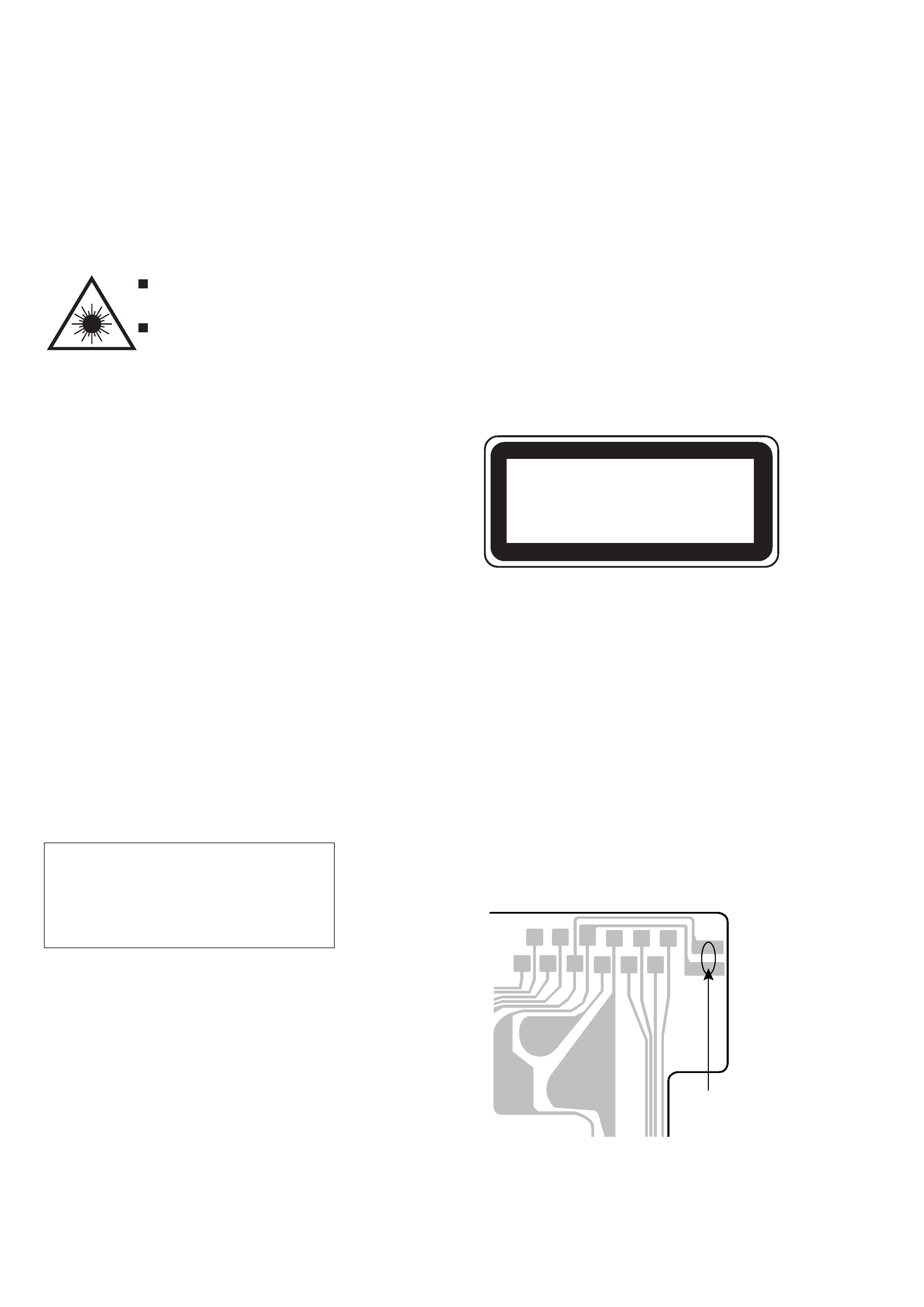
(KSS 213F)
Body or clothes electrostatic potential could
ruin laser diode in the optical block. Be sure
ground body and workbench, and use care
the clothes do not touch the diode.
1) After the connection, remove solder
shown in the right figure.
Precaution to replace Optical block
This set employs laser. Therefore, be sure to follow carefully the
instructions below when servicing.
WARNING!!
WHEN SERVICING, DO NOT APPROACH THE LASER
EXIT WITH THE EYE TOO CLOSELY. IN CASE IT IS
NECESSARY TO CONFIRM LASER BEAM EMISSION.
BE SURE TO OBSERVE FROM A DISTANCE OF MORE
THAN 30cm FROM THE SURFACE OF THE OBJECTIVE
LENS ON THE OPTICAL PICK-UP BLOCK.
Caution: Invisible laser radiation when
open and interlocks defeated avoid
exposure to beam.
Advarsel: Usynlig laserståling ved åbning,
når sikkerhedsafbrydere er ude af funktion.
Undgå udsættelse for stråling.
VAROITUS!
Laiteen Käyttäminen muulla kuin tässä käyttöohjeessa
mainitulla
tavalla
saataa
altistaa
käyt-täjän
turvallisuusluokan 1 ylittävälle näkymättömälle
lasersäteilylle.
VARNING!
Om apparaten används på annat sätt än vad som
specificeras i denna bruksanvising, kan användaren
utsättas för osynling laserstrålning, som överskrider
gränsen för laserklass 1.
PROTECTION OF EYES FROM LASER BEAM DURING SERVICING
CAUTION
Use of controls or adjustments or performance of proce-
dures other than those specified herin may result in
hazardous radiation exposure.
ATTENTION
L'utillisation de commandes, réglages ou procédures
autres que ceux spécifiés peut entraîner une dangereuse
exposition aux radiations.
ADVARSEL
Usynlig laserståling ved åbning, når sikkerhedsafbrydereer
ude af funktion. Undgå udsættelse for stråling.
This Compact Disc player is classified as a CLASS 1
LASER product.
The CLASS 1 LASER PRODUCT label is located on the
rear exterior.
CLASS 1
LASER PRODUCT
KLASSE 1
LASER PRODUKT
LUOKAN 1
LASER LAITE
KLASS 1
LASER APPARAT
Solder
PICKUP Assy P.C.B.
4
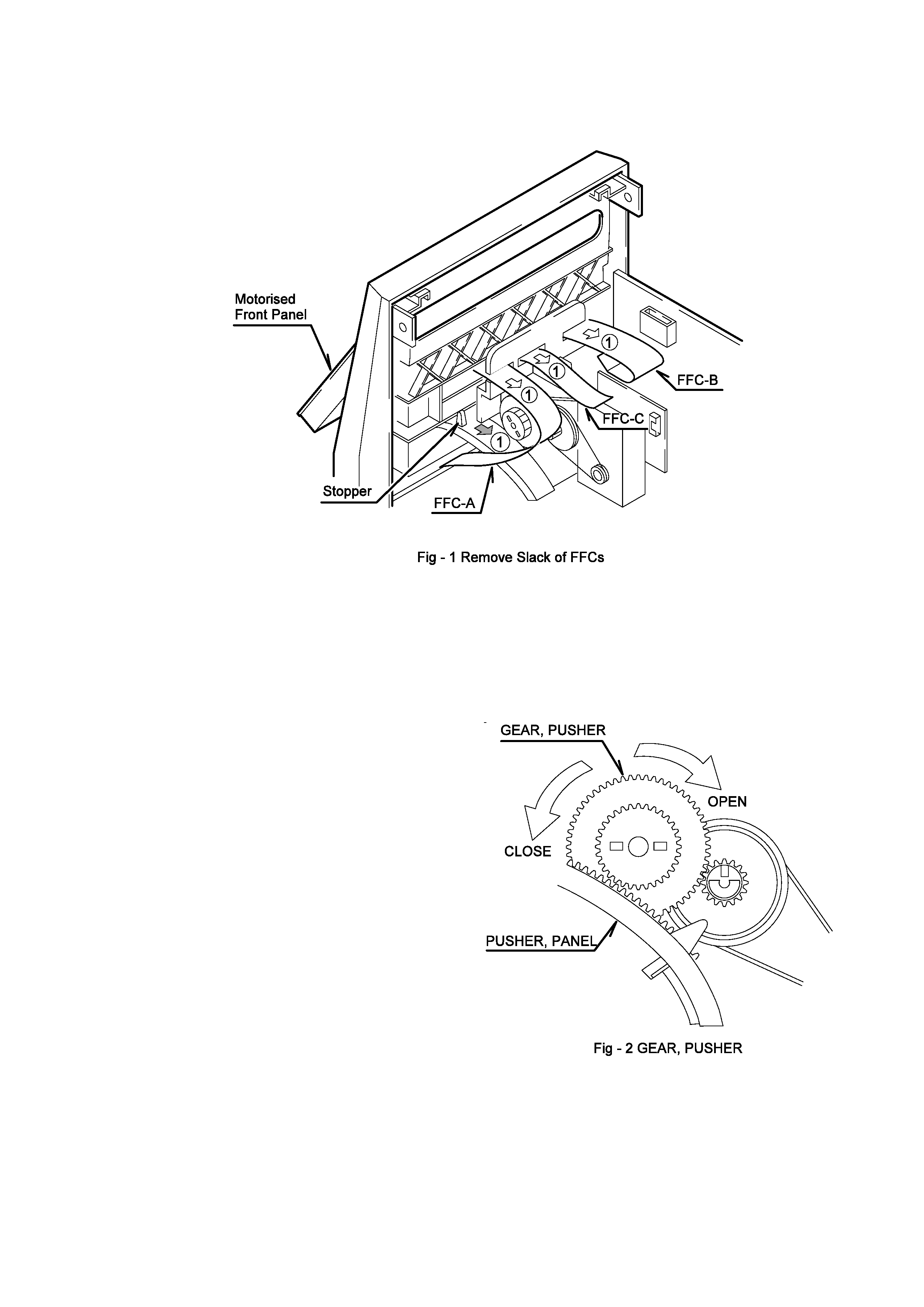
CAUTION WHEN SERVICING
The 3 FFCs connected to the Motorised Front Panel is movable with
the Motorised Front Panel.
To prevent the FFCs from being trap in between the Motorised Front
Panel and the Front Cabinet, the FFCs must be arrange as shown in
Fig. 1.
1.
Remove slack of FFCs
1)
Return the Motorised Front Panel to its upright position slowly
while at the same time pull the FFCs (FFC-A/-B/-C) near to
the slot to remove any slack that is formed in between the
Motorised Front Panel and the Front Cabinet.
Note: To remove the Motorised Front Panel, rotate GEAR, PUSHER
as shown in Fig. 2.
5
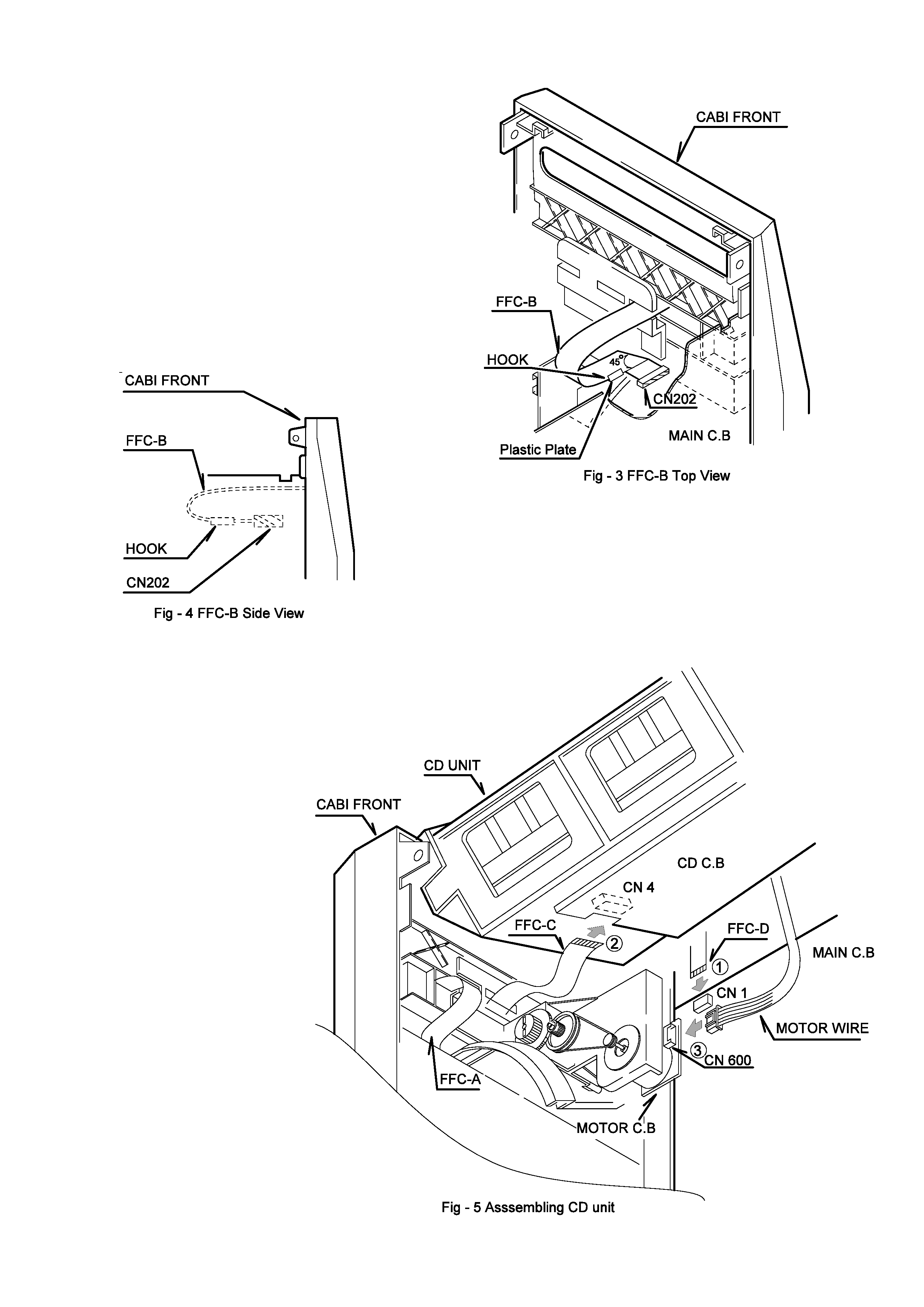
2.
Arranging FFC-B
1)
Fold the end of the FFC-B at an angle of 45 degrees.
2)
Connect FFC-B to CN202 of MAIN C.B.
3)
Put FFC-B onto the Plastic Plate to prevent it from sagging.
Note: FFC-B is easy to trap in between the CD unit and the Front
Cabinet when assembling the CD unit to the set.
Arrange FFC-B as shown in Fig. 4.
3.
Assembling CD unit
1)
Assemble CD unit to the Front Cabinet.
2)
Connect FFC-D to CN1 of MAIN C.B (1).
3)
Connect FFC-C to CN4 of CD C.B (2).
4)
Connect the motor wire to CN600 of MOTOR C.B (3).