
file:///C|/Documents%20and%20Settings/bob/My%20Documents/manualdirectory.htm
This file was downloaded and provided FREE OF CHARGE
from the ManualDirectory community.
You can find many free to download Service Manuals & Schematics at
http://www.manualdirectory.co.uk
file:///C|/Documents%20and%20Settings/bob/My%20Documents/manualdirectory.htm01/04/2007 01:34:00
SERVICE MANUAL
DA
TA
MD / CD STEREO SYSTEM
BASIC TAPE MECHANISM : 2ZM-3MK2 PR4NM
BASIC CD MECHANISM : AZG-1 ZD8RMDM
BASIC MD MECHANISM : AZG-7 DM
XR-HG5MD K, EZ
S/M Code No. 09-004-423-9R2
REVISION
· This Service Manual is the "Revision Publishing" and replaces "Simple Manual"
XR-HG5MD (K, EZ), (S/M Code No. 09-002-423-9T2).
· If requiring information about the CD mechanism, see Service Manual of
AZG-1 ZD8RMDM, (S/M Code No. 09-001-335-3NA).
· If requiring information about the MD mechanism, see Service Manual of
AZG-7 DM, (S/M Code No. 09-001-338-4N2).
XRHG5MD
SPEAKER
SYSTEM
CD
CASSEIVER
SXWNHG5
CXNHG5MD
RCZAS16
REMOTE
CONTROLLER

2
SPECIFICATIONS
<FM tuner section>
Tuning range
87.5 MHz to 108 MHz
Usable sensitivity (IHF)
16.8 dBf
Antenna terminals
75 ohms (unbalanced)
<MW tuner section>
Tuning range
530 kHz to 1710 kHz (10 kHz step)
531 kHz to 1602 kHz (9 kHz step)
Usable sensitivity
350
µV/m
Antenna
Loop antenna
<LW tuner section>
Tuning range
144 kHz to 290 kHz
Usable sensitivity
1400
µV/m
Antenna
Loop antenna
<Amplifier section>
Mid-high frequency amplifier
Power output*
Rated: 15 W + 15 W
(8 ohms, T.H.D. 1 %, 200 Hz to 20 kHz/
DIN 45500)
Reference: 18 W + 18 W
(8 ohms, T.H.D. 10 %, 200 Hz to 20 kHz
/DIN 45324)
EZ:
DIN MUSIC POWER: 32 W + 32 W
Total harmonic distortion 0.06 % (8 W, 1 kHz, 8 ohms, DIN
AUDIO)
Low frequency amplifier
Power output*
Rated: 45 W + 45 W
(6 ohms, T.H.D. 1 %, 50 Hz to 200 Hz/
DIN 45500)
Reference : 54 W + 54 W
(6 ohms, T.H.D. 10 %, 50 Hz to 200 HZ/
DIN 45324)
EZ:
DIN MUSIC POWER: 74 W + 74 W
Total harmonic distortion 0.06 % (20 W, 130 Hz, 6 ohms, DIN
AUDIO)
* without connecting to the SURROUND SPEAKERS
Inputs
VIDEO/AUX: 500 mV
DIGITAL IN
Outputs
SPEAKERS HIGH FREQ:
accept speakers of 8 ohms or more
SPEAKERS LOW FREQ:
accept speakers of 6 ohms or more
SURROUND SPEAKERS:
accept speakers of 8 to 16 ohms
PHONES (stereo jack):
accepts headphones of 32 ohms or more
CD DIGITAL OUT (OPTICAL) jack
<Cassette deck section>
Track format
4 tracks, 2 channels stereo
Frequency response
50 Hz 15000 Hz
Recording system
AC bias
Heads
Deck 1 : Playback head x 1
Deck 2 : Recording/Playback head
x 1, erase head x 1
<Compact disc player section>
Laser
Semiconductor laser (
=780 nm)
D-A converter
1 bit dual
Signal-to-noise ratio
85 dB (1 kHz, 0 dB)
Harmonic distortion
0.05 % (1 kHz, 0 dB)
Wow and flutter
Unmeasurable
<MD recorder section>
Scanning method
Non-contact optical scanner
(Semiconductor laser application)
Recording section
Magnetic polarity modulation
overwrite system
Rotation speed
Approx. 400 - 900 rpm (CLV)
Sampling frequency
44.1 kHz
No. of channels
Stereo: 2 channels
Monaural: 1 channels
A-D, D-A converter
1 bit
Frequency
20 to 20000 Hz +0.5 - 1.5dB
Wow and flutter
Unmeasurable
<Speaker system SXWNHG5>
Cabinet type
3 way, built-in subwoofer (magnetic
shielded type)
Speakers
Subwoofer:
160 mm cone type
Full range:
100 mm cone type
Super tweeter:
20 mm ceramic type
Impedance
LOW FREQ.: 6 ohms
HIGH FREQ.: 8 ohms
Output sound pressure level 87 dB/W/m
Dimensions (W x H x D)
240 x 324 x 270 mm
Weight
4.8 kg
<General>
Power requirements
230 V AC, 50 Hz
Power consumption
EZ: 150 W
K: 160 W
Power consumption in standby mode
If the power-economizing mode
is ECO OFF: 21 W
If the power-economizing mode
is ECO ON or ECO AUTO: 0.9 W
Dimensions of main unit
260 x 326.5 x 348 mm
(W x H x D)
Weight of main unit
8.4 kg
· Design and specifications are subject to change without notice.
3
CLASS 1
LASER PRODUCT
KLASSE 1
LASER PRODUKT
LUOKAN 1
LASER LAITE
KLASS 1
LASER APPARAT
This set employs laser. Therefore, be sure to follow carefully
the instructions below when servicing.
WARNING!!
WHEN SERVICING, DO NOT APPROACH THE LASER
EXIT WITH THE EYE TOO CLOSELY. IN CASE IT IS
NECESSARY TO CONFIRM LASER BEAM EMISSION.
BE SURE TO OBSERVE FROM A DISTANCE OF MORE
THAN 30cm FROM THE SURFACE OF THE OBJEC-
TIVE LENS ON THE OPTICAL PICK-UP BLOCK.
s Caution: Invisible laser radiation when
open and interlocks defeated avoid
exposure to beam.
s Advarsel: Usynlig laserståling ved åbning,
når sikkerhedsafbrydere er ude af funktion.
Undgå udsættelse for stråling.
VAROITUS!
Laiteen Käyttäminen muulla kuin tässä käyttöohjeessa
mainitulla
tavalla
saataa
altistaa
käyt-täjän
turvallisuusluokan 1 ylittävälle näkymättömälle
lasersäteilylle.
VARNING!
Om apparaten används på annat sätt än vad som
specificeras i denna bruksanvising, kan användaren
utsättas för osynling laserstrålning, som överskrider
gränsen för laserklass 1.
PROTECTION OF EYES FROM LASER BEAM DURING SERVICING
CAUTION
Use of controls or adjustments or performance of proce-
dures other than those specified herin may result in
hazardous radiation exposure.
ATTENTION
L'utillisation de commandes, réglages ou procédures
autres que ceux spécifiés peut entraîner une dangereuse
exposition aux radiations.
ADVARSEL
Usynlig laserståling ved åbning, når sikkerhedsafbrydereer
ude af funktion. Undgå udsættelse for stråling.
This Compact Disc player is classified as a CLASS 1
LASER product.
The CLASS 1 LASER PRODUCT label is located on the
rear exterior.
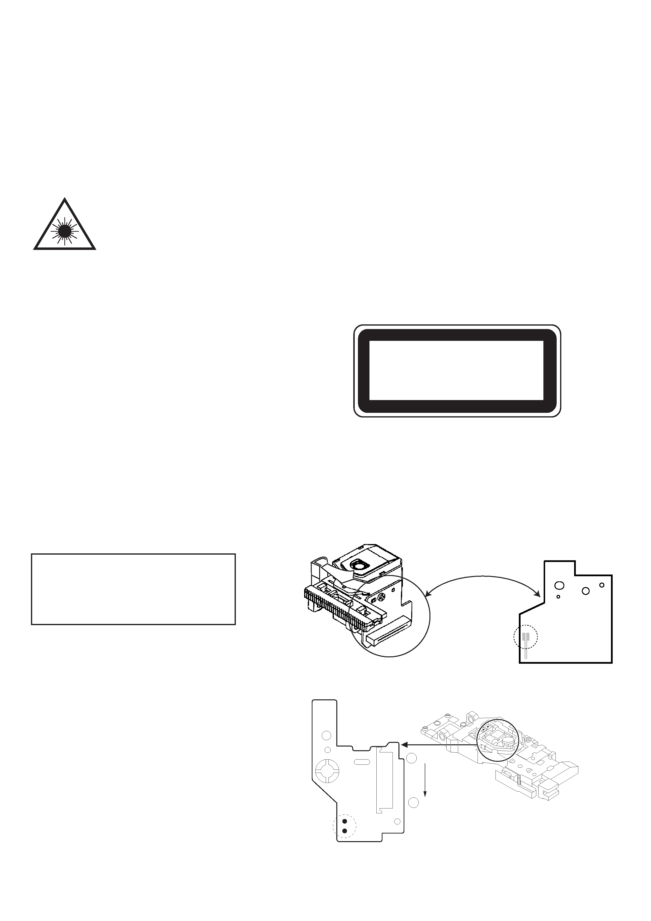
Precaution to replace Optical block
(KMS-260B / KSM-880CAB)
Body or clothes electrostatic potential could
ruin laser diode in the optical block. Be sure
ground body and workbench, and use care the
clothes do not touch the diode.
1) After the connection, remove solder shown in
right figure.
MD PICK-UP Assy P.C.B (KMS-260B)
1
VEE
21
TRK --
Solder
Pattern side
solder
CD PICK-UP Assy P.C.B (KSM-880CAB)
4
NOTE ON BEFORE STARTING REPAIR
Charging voltage (V)
Discharging
Rated power (W)
Parts number
(C101, 102)
resistor (
)
25-48
100
3
87-A00-247-090
49-140
220
5
87-A00-232-090
Note: The reference numbers (C101, C102) of the electrolytic capacitors can change depending on the models. Be sure to check the
reference numbers of the charging capacitors on schematic diagram before starting the discharging work.
2. Check items before exchanging the MICROCOMPUTER
Be sure to check the following items before exchanging the MICROCOMPUTER. Exchange the MICROCOMPUTER after confirming
that the MICROCOMPUTER is surely defective.
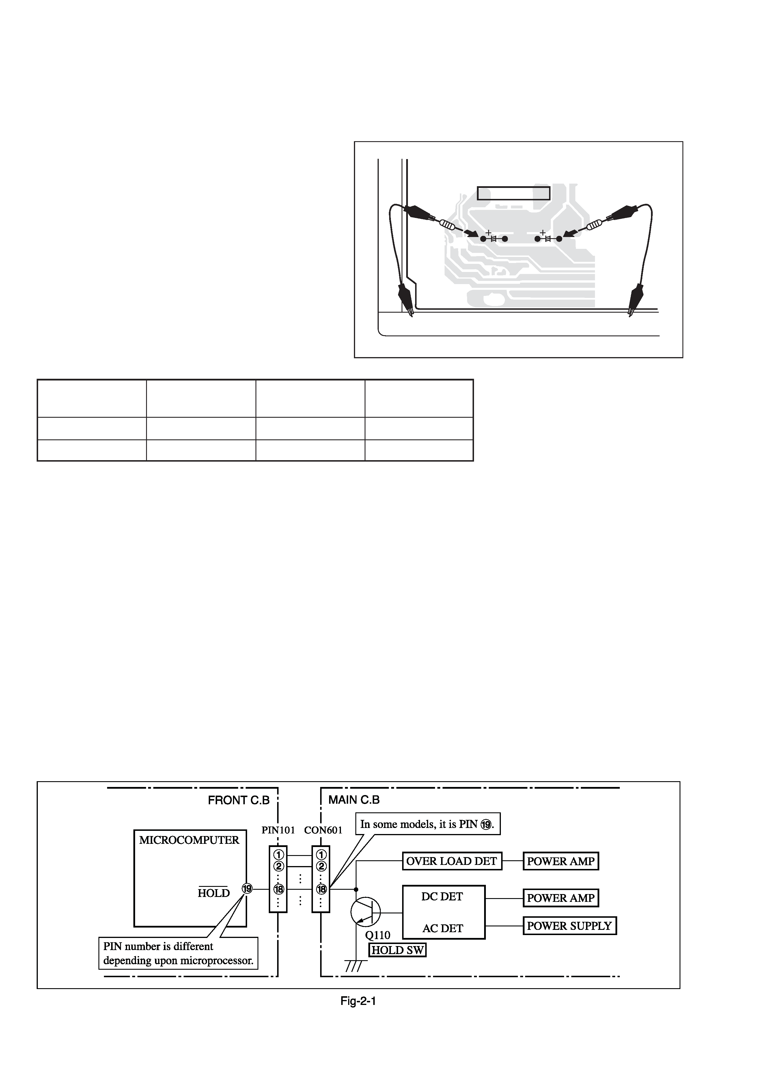
2-1. Regarding the HOLD terminal of the MICROCOMPUTER
When the HOLD terminal (INPUT) of the MICROCOMPUTER is "H", the MICROCOMPUTER is judged to be operating correctly.
When this terminal is "L", the main power cannot be turned on. Therefore, be sure to check the terminal voltage of the HOLD
terminal before exchange.
When the MICROCOMPUTER is not defective, the HOLD terminal can also go "L" when the POWER AMPLIFIER has any
abnormalities that triggers the abnormality detection circuit on the MAIN C. B. that sets the HOLD terminal to "L".
· Good or no good judgement of the MICROCOMPUTER
1
1
1
1
1 Turn on the AC main power.
2
2
2
2
2 Confirm that the main power is turned on and the HOLD terminal of the MICROCOMPUTER keeps the "H" level or not.
3
3
3
3
3 When the HOLD terminal is "L" level, the abnormality detection circuit is judged to be working correctly and the
MICROCOMPUTER is judged to be good.
1. Forced discharge of electrolytic capacitor of power supply block
When repair is going to be attempted in the set that uses relay circuit in the power supply block, electric potential is kept charged across
the electrolytic capacitors (C101, 102) even though AC power cord is removed. If repair is attempted in this condition, secondary defect
can occur.
In order to prevent the secondary trouble, perform the following measures before starting repair work.
Discharge procedure
1
1
1
1
1 Remove the AC power cord.
2
2
2
2
2 Connect a discharging resistor at an end of lead wire that
has clips at both ends. Connect the other end of the lead
wire to metal chassis.
3
3
3
3
3 Contact the other end of the discharging resistor to the
positive (+) side (+VH) of C101. (For two seconds)
4
4
4
4
4 Contact the same end of the discharging resistor as step
3
3
3
3
3 to the negative (-) side (-VH) of C102 in the same way.
(For two seconds)
5
5
5
5
5 Check that voltage across C101 and C102 has decreased
to 1 V or less using a multimeter or an oscilloscope.
Select a discharging resistor referring to the following table.
Fig-1
MAIN C.B
D101
C101
C102
22
3
4