SERVICE MANUAL
DA
TA
BASIC DVD MECHANISM : DV32BF2
MICRO COMPO STEREO/ DVD PLAYER
XR-DV700
XR-DV701
S/M Code No. 09-018-358-0N1
U(S), K(S)
EZ(S)
SYSTEM
XR-DV700 U(S)
XR-DV700 K(S)
XR-DV701 EZ(S)
DVD PLAYER
CX-SLDV700 U(S)
CX-SLDV700 K(S)
CX-SLDV701 EZ(S)
SUB WOOFER
TS-SLW700 U(S)
TS-SLW700 K(S)
TS-SLW701 EZ(S)
If requiring information about the SUB WOOFER, see Service Manual of TS-SLW700,
S/M Code No.09-019-449-2R1.
SPEAKER
SX-SLDV700YJSN

-2-
TABLE OF CONTENTS
SPECIFICATIONS ................................................................................................................................................ 3
Caution when replacing lithium battery................................................................................................................. 4
ACCESSORIES/PACKAGE LIST-1/1 .................................................................................................................. 4
PROTECTION OF EYES FROM LASER BEAM DURING SERVICING ............................................................... 5
Precaution to replace Optical block ...................................................................................................................... 6
ELECTRICAL MAIN PARTS LIST .................................................................................................................... 7-14
BLOCK DIAGRAM-1/4 (EXCEPT DVD C.B) ...................................................................................................... 15
BLOCK DIAGRAM-2/4 (MAIN : MICON BLOCK) ................................................................................................ 16
BLOCK DIAGRAM-3/4 (DVD-2/2 : DVD BLOCK) .............................................................................................. 17
BLOCK DIAGRAM-4/4 (DVD-2/2 : FRONT END) .............................................................................................. 18
WIRING-1/10 (FRONT, KEY, MOT-SW) ............................................................................................................ 19
SCHEMATIC DIAGRAM-1/18 (FRONT, KEY, MOT-SW) ................................................................................... 20
WIRING-2/10 (TUNER <U>) .............................................................................................................................. 21
SCHEMATIC DIAGRAM-2/18 (TUNER <U>) ...................................................................................................... 22
WIRING-3/10 (TUNER <K, EZ>) ........................................................................................................................ 23
SCHEMATIC DIAGRAM-3/18 (TUNER <K, EZ>) ............................................................................................... 24
WIRING-4/10 (MAIN, FAN : COMPONENT) ....................................................................................................... 25
WIRING-5/10 (MAIN, FAN : CONDUCTOR) ....................................................................................................... 26
SCHEMATIC DIAGRAM-4/18 (MAIN-1/3 : MICON) ............................................................................................. 27
SCHEMATIC DIAGRAM-5/18 (MAIN-2/3 : AC3 FILTER) ..................................................................................... 28
SCHEMATIC DIAGRAM-6/18 (MAIN-3/3 : FUN, PRO LOGIC) ............................................................................ 29
SCHEMATIC DIAGRAM-7/18 (FAN) ................................................................................................................... 30
WIRING-6/10 (DVD : COMPONENT) ................................................................................................................. 31
WIRING-7/10 (DVD : CONDUCTOR) ................................................................................................................ 32
SCHEMATIC DIAGRAM-8/18 (DVD : RF AMP) .................................................................................................. 33
SCHEMATIC DIAGRAM-9/18 (DVD : DSP) ........................................................................................................ 34
SCHEMATIC DIAGRAM-10/18 (DVD : AV DECODER) ..................................................................................... 35
SCHEMATIC DIAGRAM-11/18 (DVD : 5.1CH DECODER) ................................................................................ 36
SCHEMATIC DIAGRAM-12/18 (DVD : VIDEO ENCODER) ............................................................................... 37
SCHEMATIC DIAGRAM-13/18 (DVD : POWER, SPINDLE DRIVER) ............................................................... 38
SCHEMATIC DIAGRAM-14/18 (DVD : µ-COM) .................................................................................................. 39
SCHEMATIC DIAGRAM-15/18 (DVD : SYSCON) .............................................................................................. 40
WIRING-8/10 (SUPPLY, HP) .............................................................................................................................. 41
SCHEMATIC DIAGRAM-16/18 (SUPPLY, HP) ................................................................................................... 42
WIRING-9/10 (PT) .............................................................................................................................................. 43
SCHEMATIC DIAGRAM-17/18 (PT) ................................................................................................................... 44
WIRING-10/10 (JACK-SV, JACK-AU) ................................................................................................................. 45
SCHEMATIC DIAGRAM-18/18 (JACK-SV, JACK-AU) ........................................................................................ 46
TRANSISTOR ILLUSTRATION-1/1 .................................................................................................................... 47
FL (BCQ-0 ) GRID ASSIGNMENT/ANODE CONNECTION-1/1 ......................................................................... 48
WAVE FORM ................................................................................................................................................ 49-50
DVD TEST MODE ........................................................................................................................................ 51-53
IC BLOCK DIAGRAM .................................................................................................................................... 54-57
IC DESCRIPTION ......................................................................................................................................... 58-80
MECHANICAL EXPLODED VIEW ................................................................................................................. 81-86
MECHANICAL PARTS LIST .......................................................................................................................... 87-88
SPEAKER PARTS LIST ..................................................................................................................................... 89
-3-
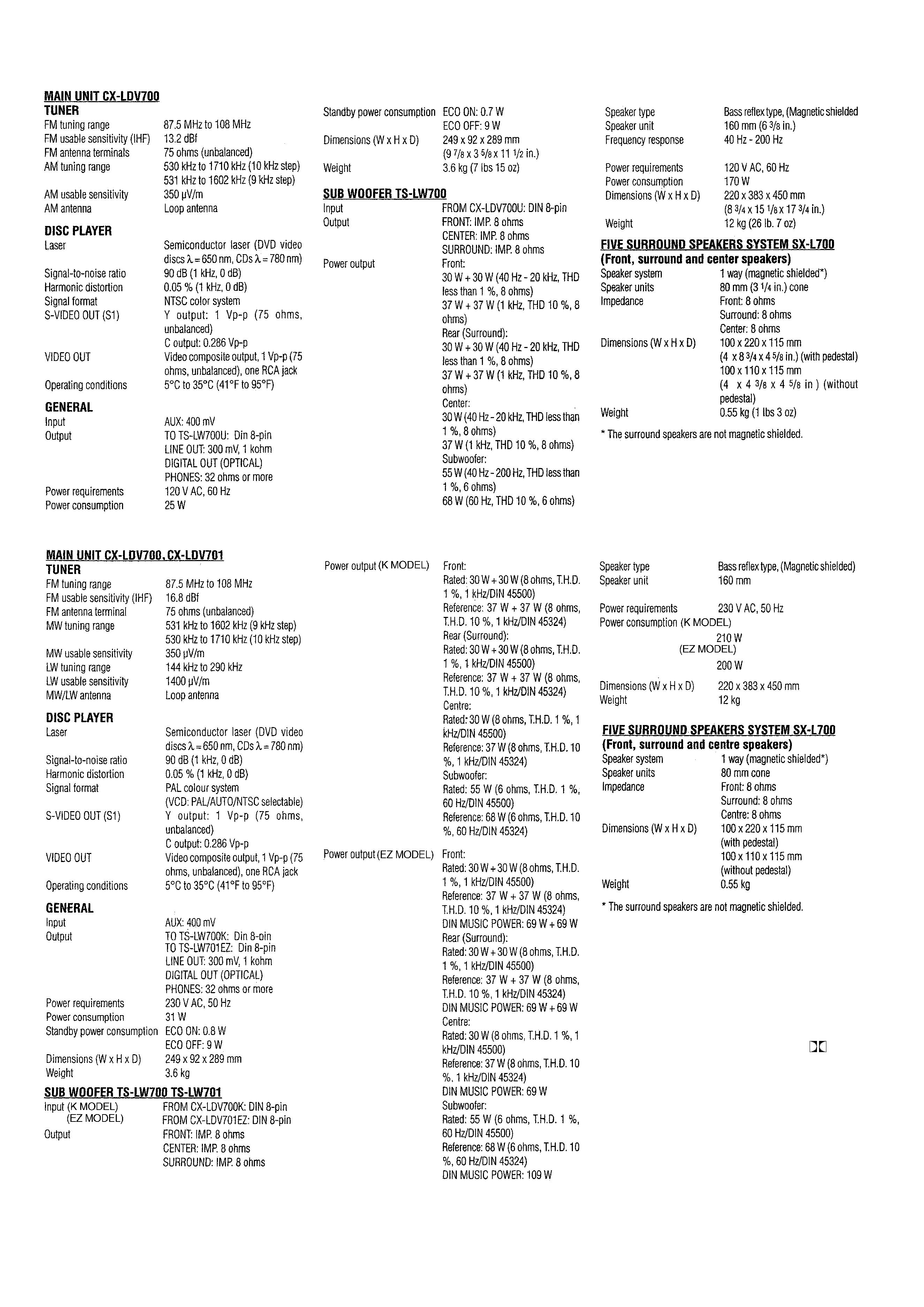
SPECIFICATIONS
U MODEL
K, EZ MODEL
· Design and specifications are subject to
change withoutnotice.
· Dolby noise reduction manufactured under
license from Dolby Laboratories Licensing
Corporation.
"DOLBY" and the double-D symbol
and
"PRO LOGIC" are trademarks of Dolby
Laboratories Licensing Corporation.
Laboratories Licensing Corporation.
· Manufactured under license from Digital Theater
Systems, Inc.
US Pat. No.5,451,942 and other worldwide patents
Issued and pending. "D T S" and "D T S Digital
Surround" are trade marks of Digital Theater
Systems, Inc. Systems, Inc. c 1996 Digital Theater
systems, Inc. All rights reserved.

-4-
Danger of explosion if battery is incorrectly replaced.
Replace only with the same (CR2025) or equivalent type recommended
by the manufacturer.
Discard used batteries according to the manufacturer's instruction.
Caution when replacing lithium battery
REF. NO
PART NO.
KANRI
DESCRIPTION
NO.
ACCESSORIES/PACKAGE LIST-1/1
1
8B-CQA-907-010
IB,EZ(4L)M<701 EZSM>
1
8B-CQA-906-010
IB,EZ(5L)M<701 EZSM>
1
8B-CQA-905-010
IB,K(E)M<700 KSM>
1
8B-CQA-903-010
IB,U(ESF)M<700 USM>
2
8B-CQA-951-010
RC UNIT,RC-BAT08
3
8B-CQA-961-010
CORD ASSY,DIN 13P-5M<700 USM>
3
87-A80-167-010
CORD,PIN 1PY 150CM
4
87-006-225-010
AM LOOP ANT NC2<700 USM>
5
87-043-115-010
ANT,FEEDER FM<700 USM>
5
87-A90-118-010
ANT,WIRE FM (Z)<EXCEPT 700 USM>
-5-
PROTECTION OF EYES FROM LASER BEAM DURING SERVICING
VAROITUS!
Laiteen Käyttäminen muulla kuin tässä käyttöohjeessa mainit-
ulla tavalla saattaa altistaa käyt-täjän turvallisuusluokan 1 ylit-
tävälle näkymättömälle lasersäteilylle.
VARNING!
Om apparaten används på annat sätt än vad som specificeras i
denna bruksanvising, kan användaren utsättas för osynling
laserstrålning, som överskrider gränsen för laserklass 1.
Caution: Invisible laser radiation when
open and interlocks defeated avoid expo-
sure to beam.
Advarsel:Usynling laserståling ved åbning,
når sikkerhedsafbrydere er ude af funktion.
Undgå udsættelse for stråling.
CAUTION
Use of controls or adjustments or performance of procedures
other than those specified herein may result in hazardous
radiation exposure.
Danger of explosion if battery is incorrectly replaced.
Replace only with the same (CR2025) or equivalent type recommended
by the manufacturer.
Discard used batteries according to the manufacturer's instruction.
ATTENTION
L'utilisation de commandes, réglages ou procédures autres que
ceux spécifiés peut entraîner une dangereuse exposition aux
radiations.
ADVARSEL!
Usynlig laserståling ved åbning, når sikkerhedsafbrydereer ude
af funktion. Undgå udsættelse for stråling.
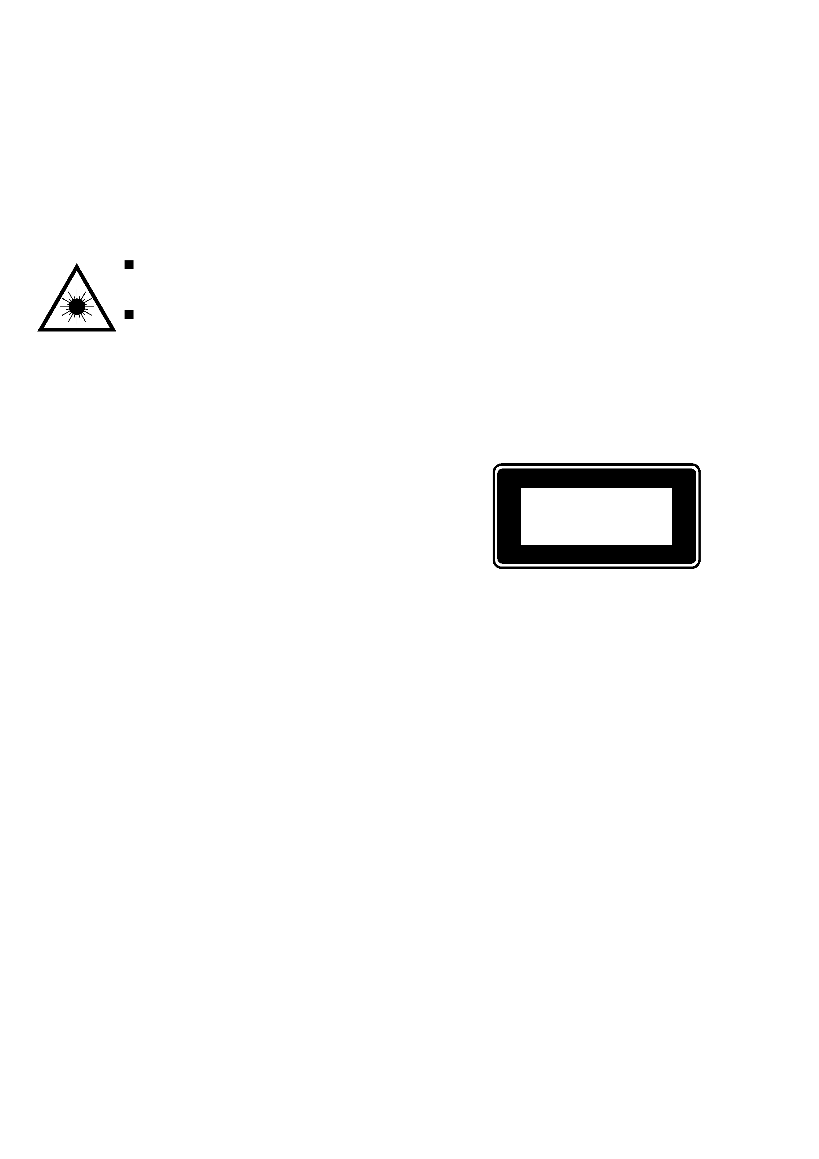
This Compact Disc player is classified as a CLASS 1 LASER
product.
The CLASS 1 LASER PRODUCT label is located on the rear
exterior.
This set employs laser. Therefore, be sure to follow carefully the
instructions below when servicing.
WARNING!
WHEN SERVICING, DO NOT APPROACH THE LASER EXIT
WITH THE EYE TOO CLOSELY. IN CASE IT IS NECESSARY TO
CONFIRM LASER BEAM EMISSION. BE SURE TO OBSERVE
FROM A DISTANCE OF MORE THAN 30cm FROM THE
SURFACE OF THE OBJECTIVE LENS ON THE OPTICAL
PICK-UP BLOCK.
CLASS 1
KLASSE 1
LUOKAN 1
KLASS 1
LASER PRODUCT
LASER PRODUKT
LASER LAITE
LASER APPARAT