SERVICE MANUAL
DA
TA
DVD PLAYER
XD-DV370
S/M Code No. 09-009-349-9N1
HR(N) EZ(N, B) K(N)
U(B)
DP2[6721R-0308A](HR/K/U)
DP3[6721R-0309A](EZ)
BASIC DVD/CD MECHANISM :
If requiring information about the ELECTRICAL ADJUSTMENT & MECHANSIM
ADJUSTMENT & MECHANISM PARTS LOCATION <EZ> & MECHANISM DISASSEMBLY
<EZ> & FL GRID ASSINGMENT/ANODE CONNECTION/PIN CONNECTION.
see Supplement Service manual of XD-DV370(HR/U/K/EZ) (S/M Code No. 09-00C-349-9S1)
<HR(N)>
<Except for HR(N)>

-2-
TABLE OF CONTENTS
SPECIFICATIONS ........................................................................................................................................................................... 3
PROTECTION OF EYES FROM LASER BEAM DURING SERVING ............................................................................................ 4
ACCESSORIES LIST ...................................................................................................................................................................... 5
DISASSEMBLY INSTRUCTIONS ............................................................................................................................................. 6 ~ 7
ELECTRICAL MAIN PARTS LIST ........................................................................................................................................... 8 ~ 10
TRANSISTOR ILLUSTRATION ..................................................................................................................................................... 11
BLOCK DIAGRAM - 1 (OVERALL) <HR> ..................................................................................................................................... 12
BLOCK DIAGRAM - 2 (OVERALL) <Except HR> ......................................................................................................................... 13
BLOCK DIAGRAM - 3 (POWER) <U> .......................................................................................................................................... 14
BLOCK DIAGRAM - 4 (POWER) <Except U> .............................................................................................................................. 15
BLOCK DIAGRAM - 5 (RF/CD DSP/DVD SERVO) ...................................................................................................................... 16
BLOCK DIAGRAM - 6 (AUDIO) .................................................................................................................................................... 17
BLOCK DIAGRAM - 7 (MPEG) <HR> ........................................................................................................................................... 18
BLOCK DIAGRAM - 8 (MPEG) <Except HR> ............................................................................................................................... 19
BLOCK DIAGRAM - 9 (µ-COM) .................................................................................................................................................... 20
BLOCK DIAGRAM - 10 (KARAOKE) <HR> .................................................................................................................................. 21
WIRE HARNESS DIAGRAM ......................................................................................................................................................... 22
SCHEMATIC DIAGRAM - 1 (MAIN - 1/5, AUDIO SECTION) ........................................................................................................ 23
SCHEMATIC DIAGRAM - 2 (MAIN - 2/5, DRIVE & RF SECTION) ............................................................................................... 24
SCHEMATIC DIAGRAM - 3 (MAIN - 3/5, DVD DSP SECTION) ................................................................................................... 25
SCHEMATIC DIAGRAM - 4 (MAIN - 4/5, MPEG SECTION) <HR> .............................................................................................. 26
SCHEMATIC DIAGRAM - 5 (MAIN - 4/5, MPEG SECTION) <Except HR> .................................................................................. 27
SCHEMATIC DIAGRAM - 6 (MAIN - 5/5, MAIN µ-COM SECTION) ............................................................................................. 28
SCHEMATIC DIAGRAM - 7 (INTERFACE - 1/3, TIMER SECTION) (KEY1, KEY2 SECTION) <HR> ......................................... 31
SCHEMATIC DIAGRAM - 8 (INTERFACE - 1/3, TIMER SECTION) (KEY1, KEY2 SECTION) <Except HR> ............................. 32
SCHEMATIC DIAGRAM - 9 (INTERFACE - 2/3, JACK SECTION) <HR> ................................................................................... 33
SCHEMATIC DIAGRAM - 10 (INTERFACE - 2/3, JACK SECTION) <U> .................................................................................... 34
SCHEMATIC DIAGRAM - 11 (INTERFACE - 2/3, JACK SECTION) <EZ, K> ............................................................................... 35
SCHEMATIC DIAGRAM - 12 (INTERFACE - 3/3, POWER SECTION) <U> ................................................................................ 36
SCHEMATIC DIAGRAM - 13 (INTERFACE - 3/3, POWER SECTION) <Except U> .................................................................... 37
WIRING - 1 (MAIN C.B) <HR> ...................................................................................................................................................... 29
WIRING - 2 (MAIN C.B) <Except HR> .......................................................................................................................................... 30
WIRING - 3 (INTERFACE C.B) <HR> ........................................................................................................................................... 38
WIRING - 4 (INTERFACE C.B) <U> ............................................................................................................................................. 39
WIRING - 5 (INTERFACE C.B) <EZ, K> ....................................................................................................................................... 40
WIRING - 6 (KEY1, KEY2 C.B) ..................................................................................................................................................... 41
WAVEFORMS ....................................................................................................................................................................... 42 ~ 43
IC BLOCK DIAGRAM ............................................................................................................................................................ 44 ~ 45
IC DESCRIPTION ................................................................................................................................................................. 46 ~ 67
MECHANICAL EXPLODED VIEW 1/1 .......................................................................................................................................... 68
MECHANICAL MAIN PARTS LIST 1/1 ......................................................................................................................................... 69
COLOR NAME TABLE .................................................................................................................................................................. 70
DVD MECHANISM EXPLODED VIEW 1/1 ................................................................................................................................... 71
DVD MECHANISM MAIN PARTS LIST 1/1 ................................................................................................................................... 72
ELECTRICAL TROUBLESHOOTING GUIDE ....................................................................................................................... 73 ~ 83
DVD MECHANISM PARTS LOCATION <Except EZ> .................................................................................................................. 84
DVD MECHANISM DISASSEMBLY <Except EZ> ................................................................................................................ 85 ~ 87
-3-
SPECIFICATIONS
230 V AC, 50 Hz <K>
Power supply
110 - 240 V AC, 50/60 Hz <HR, EZ>
Power consumption
16 W
Weight
3.2 kg
External dimensions 430
× 88 × 245 mm (w × h × d)
Laser
Semicounductor laser,
wave length 650/750 nm
Signal format
PAL/NTSC
Supported discs
DVD video discs
12 cm (single-sided single-layer,
single-sided
double-layer,
double-sided-double layer)
8 cm (single-sided single-layer,
single-sided
double-layer,
double-sided-double layer)
Compact discs (CD-DA, video CD)
12 cm and 8 cm discs
S video output
Y output: 1 Vp-p (75 ohms, sync
negative)
C output: 0.286 Vp-p
1 Mini DIN 4 pin
Video output
Video composite output
1 Vp-p (75 ohms, sync negative)
1 RCA jack
1 Scart connector
Audio output
Digital output
0.5 Vp-p (75 ohms)
1 Fiber optical connector
1 RCA jack
Analogue output
2.0 Vr ms (1kHz, 0dB, 330
ohms)
1 RCA jacks (L/R)
Audio output characteristics
Signal to noise ratio
More than 105 dB (EIAJ)
Dynamic range
More than 95 dB (EIAJ)
Harmonic distortion
0.003%
Frequency range:
CD / VCD: 2 Hz to 20 kHz
DVD: 2Hz to 22kHz (48kHz
sampling)
2Hz to 44kHz (96kHz
sampling)
Wow and flutter: unmeasurable
Operating conditions
Manufactured under license from Dolby
Laboratories. Dolby , Pro Logic and the double-
D symbol are trademarks of Dolby Laboratories.
Confidential unpublished works. c1992-1997 Dolby
Laboratories. All rights reserved.
Manufactured under license from Digital Theater
Systems, Ino. US Pat. No. 5,451,942 and other
worldwide patents issued and pending. DTS and
DTS Digital Surround are trademarks of Digital
Theater Systems, Inc. c1996 Digital Theater
systems, Ino. All rights reserved.
Spatializer¤ 3-D Stereo, Spatializer N-2-2 (TM)
and the circle-in-square device are trademarks
owned by Desper Products, Inc,.
Power supply
120 V AC, 60 Hz
Power consumption
16 W
Weight
3.2 kg (7.1 lbs)
External dimensions 430
× 88 × 245 mm (w × h × d)
(17
× 3.5 × 9.9 inches)
Signal format
NTSC
Supported discs
DVD video discs
12 cm (single-sided single-layer,
single-sided
double-layer,
double-sided-double layer)
8 cm (single-sided single-layer,
single-sided
double-layer,
double-sided-double layer)
Compact discs (CD-DA, video CD)
12 cm and 8 cm discs
S video output
Y output: 1 Vp-p (75 ohms, sync
negative)
C output: 0.286 Vp-p
1 Mini Din 4 pin
Video output
Video composite output
1 Vp-p (75 ohms, sync negative)
1 RCA jack
Video component output
Y output: 1 Vp-p (75 ohms, sync
negative)
1 RCA jack
PB,PR output: 0.7 Vp-p (75 ohms)
1 RCA jacks (PB,PR)
Video component output <HR>
Y output: 1 Vp-p (75 ohms, sync
negative)
1 RCA jack
PB,PR output: 0.7 Vp-p (75 ohms)
1 RCA jacks (PB,PR)
Audio output
Digital output
0.5 Vp-p (75 ohms)
1 Fiber optical connector
Analog output
2.0 Vr ms (1kHz, 0dB, 330
ohms)
2 RCA jacks (L/R)
Audio output characteristics
Signal to noise ratio
More than 105 dB (EIAJ)
Dynamic range
More than 95 dB (EIAJ)
Harmonic distortion
0.003%
Frequency range:
CD / VCD: 2 Hz to 20 kHz
DVD: 2Hz to 22kHz (48kHz
sampling)
2Hz to 44kHz (96kHz
sampling)
Wow and flutter: unmeasurable
Operating conditions
<HR, EZ, K MODELS>
<U MODEL>
Design and specifications are subject to change without notice.
-4-
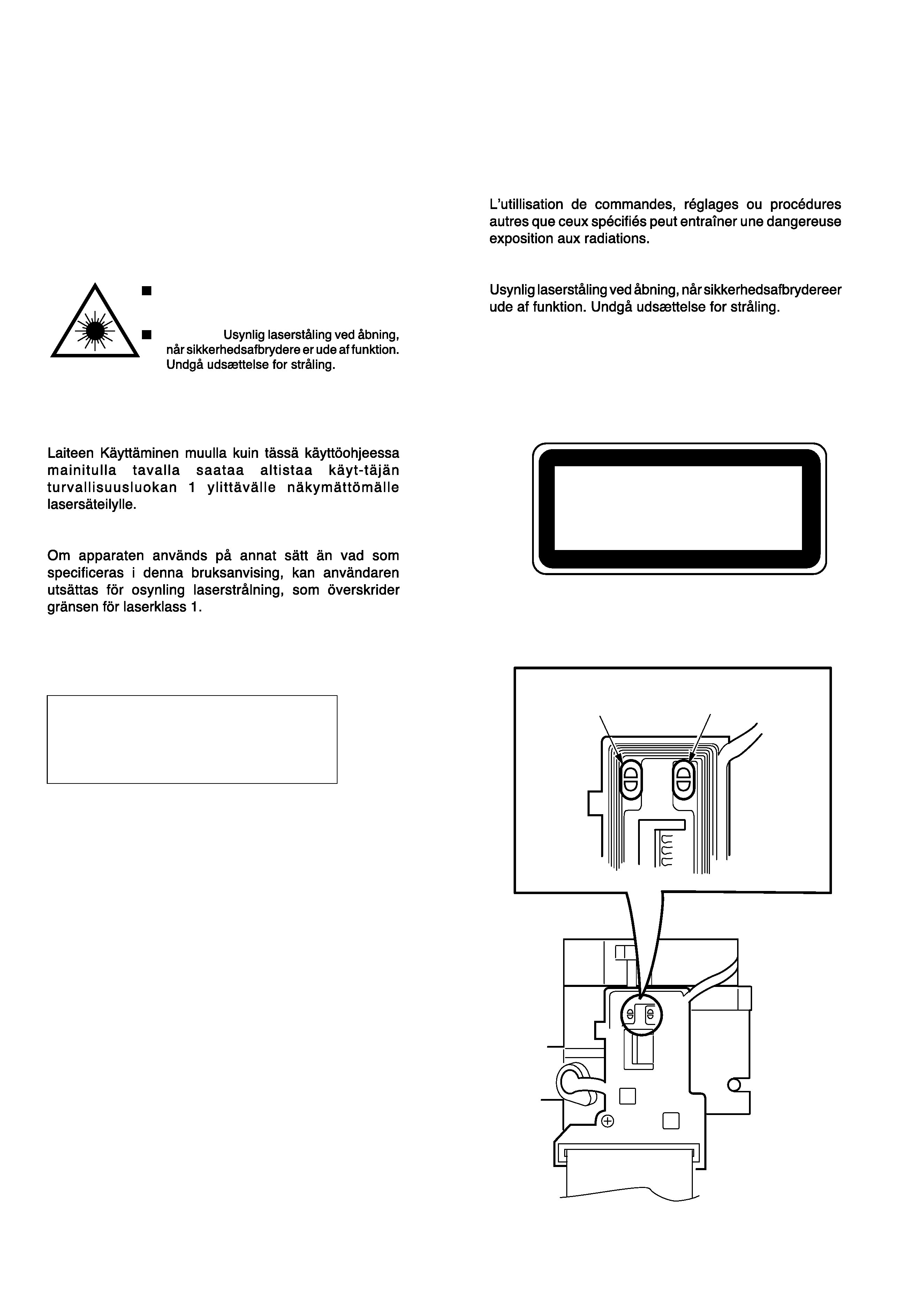
PROTECTION OF EYES FROM LASER BEAM DURING SERVICING
This set employs laser. Therefore, be sure to follow carefully the
instructions below when servicing.
WARNING!
WHEN SERVICING, DO NOT APPROACH THE LASER
EXIT WITH THE EYE TOO CLOSELY. IN CASE IT IS
NECESSARY TO CONFIRM LASER BEAM EMISSION.
BE SURE TO OBSERVE FROM A DISTANCE OF MORE
THAN 30cm FROM THE SURFACE OF THE OBJECTIVE
LENS ON THE OPTICAL PICK-UP BLOCK.
Caution: Invisible laser radiation when
open and interlocks defeated avoid
exposure to beam.
Advarsel:
VAROITUS!
VARNING!
CAUTION
Use of controls or adjustments or performance of proce-
dures other than those specified herin may result in
hazardous radiation exposure.
ATTENTION
ADVARSEL!
This Compact Disc player is classified as a CLASS 1
LASER product.
The CLASS 1 LASER PRODUCT label is located on the
rear exterior.
CLASS 1
LASER PRODUCT
KLASSE 1
LASER PRODUKT
LUOKAN 1
LASER LAITE
KLASS 1
LASER APPARAT
Body or clothes electrostatic potential could
ruin laser diode in the optical block. Be sure
ground body and workbench, and use care
the clothes do not touch the diode.
1) After the connection, remove solder
shown in the figures below.
Precaution to replace Optical block
Solder short for
DVD laser diode
Solder short for
CD laser diode
(SPU3140)

-5-
REF. NO
PART NO.
KANRI
DESCRIPTION
NO.
ACCESSORIES LIST
1
S8-35R-S00-12X
INSTRUCTION ASSY<HRN>
1
S8-35R-S00-12W
INSTRUCTION ASSY<UB>
1
S8-35R-S00-12V
INSTRUCTION ASSY<KN>
1
S8-35R-S00-12Z
INSTRUCTION ASSY<EZB,EZN>
2
S7-11R-2N0-13F
REMOTE CONTROLLER ASSY<HRN>
2
S7-11R-2N0-13D
REMOTE CONTROLLER ASSY<UB,EZB>
2
S7-11R-2N0-13E
REMOTE CONTROLLER ASSY<KN,EZN>
3
S5-640-17B-000
PLUG ASSY PHONE CORD 1WAY
3
S5-640-18B-000
PLUG ASSY PHONO CORD