BASIC DVD MECHANISM : LDM-H109
(6721R-0300A)
DVD PLAYER
XD-DV290
S/M Code No. 09-99C-337-5R1
U(B)
SERVICE MANUAL
REVISION
DA
TA
This Service Manual is the "Revision Publishing" and replaces "Simple Manual"
(S/M Code No.09-99C-337-5T1).

2
TABLE OF CONTENTS
SPECIFICATIONS .................................................................................................................................. 3
ACCESSORIES/PACKAGE LIST ........................................................................................................... 3
PROTECTION OF EYES FROM LASER BEAM DURING SERVICING/
Precaution to replace Optical block ......................................................................................................... 4
DISASSEMBLY INSTRUCTIONS ...................................................................................................... 5-10
ELECTRICAL MAIN PARTS LIST ........................................................................................................ 11
TRANSISTOR ILLUSTRATION ............................................................................................................ 12
BLOCK DIAGRAM-1 (OVERALL) ......................................................................................................... 13
BLOCK DIAGRAM-2 (POWER) ............................................................................................................ 14
BLOCK DIAGRAM-3 (RF/DSP/SERVO) ............................................................................................... 15
BLOCK DIAGRAM-4 (AUDIO) .............................................................................................................. 16
BLOCK DIAGRAM-5 (MPEG) ............................................................................................................... 17
BLOCK DIAGRAM-6 (SYSTEM CONTROL) ........................................................................................ 18
WIRING-1 (MAIN: COMPONENT SIDE) ........................................................................................ 19, 20
WIRING-2 (MAIN: CONDUCTOR SIDE) ........................................................................................ 21, 22
SCHEMATIC DIAGRAM-1 (MAIN 1/5) ............................................................................................ 23, 24
SCHEMATIC DIAGRAM-2 (MAIN 2/5) ............................................................................................ 25, 26
SCHEMATIC DIAGRAM-3 (MAIN 3/5) ............................................................................................ 27, 28
SCHEMATIC DIAGRAM-4 (MAIN 4/5) ............................................................................................ 29, 30
SCHEMATIC DIAGRAM-5 (MAIN 5/5) ............................................................................................ 31, 32
SCHEMATIC DIAGRAM-6 (JACK) ................................................................................................. 33, 34
WIRING-3 (JUNCTION/JACK) ........................................................................................................ 35, 36
SCHEMATIC DIAGRAM-7 (JUNCTION) ........................................................................................ 37, 38
WIRING-4 (TIMER/KEY/POWER) .................................................................................................. 39, 40
SCHEMATIC DIAGRAM-8 (TIMER/KEY) ....................................................................................... 41, 42
SCHEMATIC DIAGRAM-9 (POWER) ............................................................................................. 43, 44
WAVE FORM ................................................................................................................................... 45-47
TROUBLE-SHOOTING .................................................................................................................... 48-57
LCD DISPLAY ....................................................................................................................................... 58
IC DESCRIPTION ............................................................................................................................ 59-77
IC BLOCK DIAGRAM ....................................................................................................................... 78-80
MECHANICAL EXPLODED VIEW 1/1 .................................................................................................. 81
MECHANICAL PARTS LIST 1/1 ........................................................................................................... 82
MECHANISM EXPLODED VIEW 1/1 ............................................................................................. 83, 84
MECHANISM PARTS LIST 1/1 ............................................................................................................. 85

3
SPECIFICATIONS
DVD PLAYER
Power supply
120 V, 60 Hz
Power consumption
20 W
Weight
3.5 kg (7.7 lbs)
External dimensions
430 * 91 * 293 (W * H * D)
Signal system
NTSC
Laser
Semiconductor laser, wavelength 650 nm
Frequency range (digital audio)
2 Hz to 44 kHz
Signal-to-noise ratio (digital audio)
More than 105 dB (EIAJ)
Audio dynamic range (digital audio)
More than 95 dB (EIAJ)
Harmonic distortion (digital audio)
0.003%
Wow and flutter
Below measurable level (less than +0.001% (W.PEAK)) (EIAJ)
Operating conditions
Temperature : 41°F to 95°F,
Operation status : Horizontal
OUTPUTS
Video outputs
1.0 V (p-p), 75
, negative sync., RCA jack * 1
S video outputs
(Y) 1.0 V (p-p), 75
, negative sync.,Mini DIN 4-pin * 1
(C) 0.286 V (p-p), 75
Component video output
(Y) 1.0 V (p-p), 75
, negative sync., RCA jack * 1
(Pb)/ (Pr) 0.7 V (p-p), 75
Audio output (digital audio)
0.5 V (p-p), 75
, RCA jack * 1
Audio output (optical audio)
Optical connector * 1
Audio output (analog audio)
2.0 Vrms (1 kHz, 0 dB), 330
, RCA jack (L, R) * 2
· Design and specifications are subject to change without notice.
· Weight and dimensions shown are approximate.
· Dolby noise reduction manufactured under license from
Dolby Laboratories Licensing Corporation.
"DOLBY" and the double-D symbol
and "PRO LOGIC" are trademarks of Dolby Laboratories
Licensing Corporation.
Laboratories Licensing Corporation.
· Manufactured under license from Digital Theater Systems, Inc.
US Pat. No. 5,451,942 and other worldwide patents issued and
pending. "DTS" and "DTS Digital Surround" are trademarks of
Digital Theater Systems, Inc. c 1996 Digital Theater systems,
Inc. All rights reserved.
REF. NO
PART NO.
KANRI
DESCRIPTION
NO.
ACCESSORIES/PACKAGE LIST
1
S8-35R-S00-08G
INSTRUCTION BOOK DVD-2520N
2
S7-11R-2N0-13A
DVD-2520
REM
3
S8-615-20G-000
DVD-2520N CABLE ASSY
4
S5-640-17B-000
PLUG ASSY 1WAY(YL)
5
S5-640-18B-000
PLUG ASSY 2WAY(RD/WH)
4
PROTECTION OF EYES FROM LASER BEAM DURING SERVICING
VAROITUS!
Laiteen Käyttäminen muulla kuin tässä käyttöohjeessa mainit-
ulla tavalla saattaa altistaa käyt-täjän turvallisuusluokan 1 ylit-
tävälle näkymättömälle lasersäteilylle.
VARNING!
Om apparaten används på annat sätt än vad som specificeras i
denna bruksanvising, kan användaren utsättas för osynling
laserstrålning, som överskrider gränsen för laserklass 1.
Caution: Invisible laser radiation when
open and interlocks defeated avoid expo-
sure to beam.
Advarsel:Usynling laserståling ved åbning,
når sikkerhedsafbrydere er ude af funktion.
Undgå udsættelse for stråling.
CAUTION
Use of controls or adjustments or performance of procedures
other than those specified herein may result in hazardous
radiation exposure.
ATTENTION
L'utilisation de commandes, réglages ou procédures autres que
ceux spécifiés peut entraîner une dangereuse exposition aux
radiations.
ADVARSEL!
Usynlig laserståling ved åbning, når sikkerhedsafbrydereer ude
af funktion. Undgå udsættelse for stråling.
This Compact Disc player is classified as a CLASS 1 LASER
product.
The CLASS 1 LASER PRODUCT label is located on the rear
exterior.
This set employs laser. Therefore, be sure to follow carefully the
instructions below when servicing.
WARNING!
WHEN SERVICING, DO NOT APPROACH THE LASER EXIT
WITH THE EYE TOO CLOSELY. IN CASE IT IS NECESSARY TO
CONFIRM LASER BEAM EMISSION. BE SURE TO OBSERVE
FROM A DISTANCE OF MORE THAN 30cm FROM THE
SURFACE OF THE OBJECTIVE LENS ON THE OPTICAL
PICK-UP BLOCK.
CLASS 1
KLASSE 1
LUOKAN 1
KLASS 1
LASER PRODUCT
LASER PRODUKT
LASER LAITE
LASER APPARAT
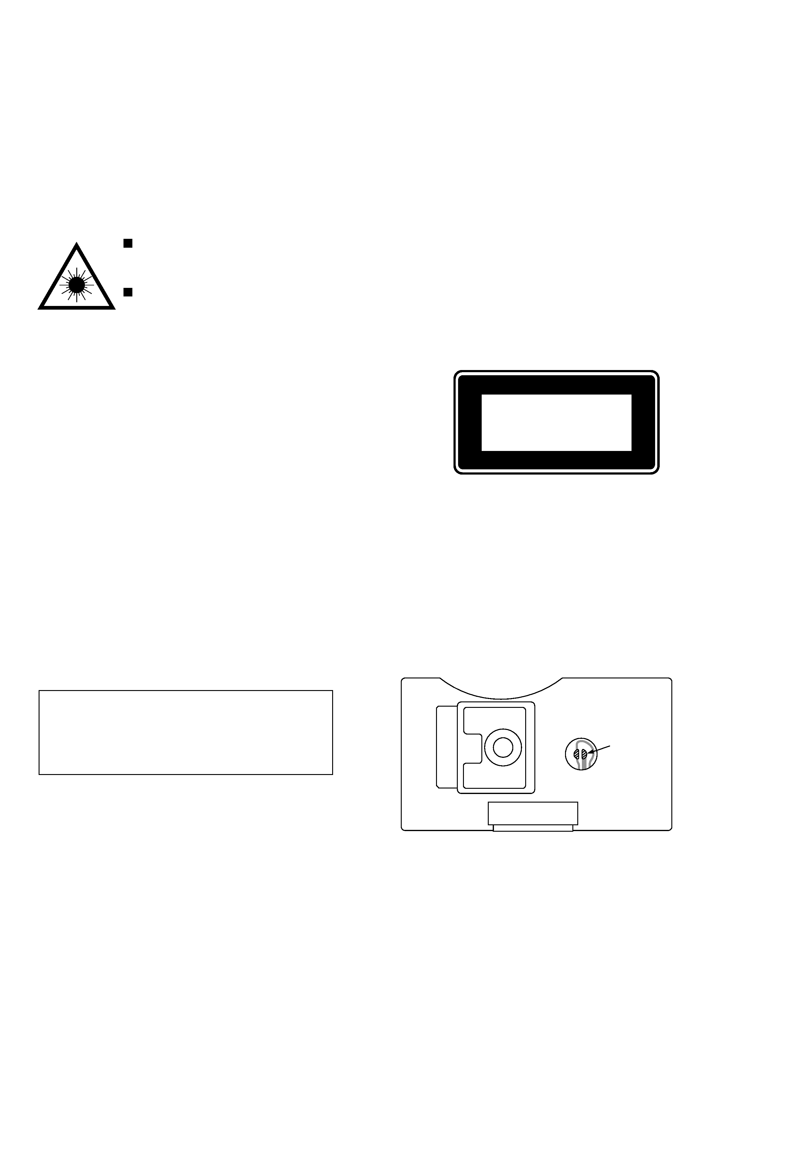
Precaution to replace Optical block
(LPC-512A)
1) After the connection, remove solder shown in
the right figure.
Body or clothes electrostatic potential could ruin
laser diode in the optical block. Be sure ground
body and workbench, and use care the clothes
do not touch the diode.
Solder
5
DISASSEMBLY INSTRUCTIONS
CAUTION BEFORE STARTING SERVICING
Electronic parts are susceptible to static electricity and may easily damaged, so do not forget to take a proper
grounding treatment as required.
Many screws are used inside the unit. To prevent missing, dropping, etc. of the screws, always use a
magnetized screw driver in servicing. Several kinds of screws are used and some of them need special
cautions. That is, take care of the tapping screws securing molded parts and fine pitch screws used to secure
metal parts. If they are used improperly, the screw holes will be easily damaged and the parts can not be
fixed.
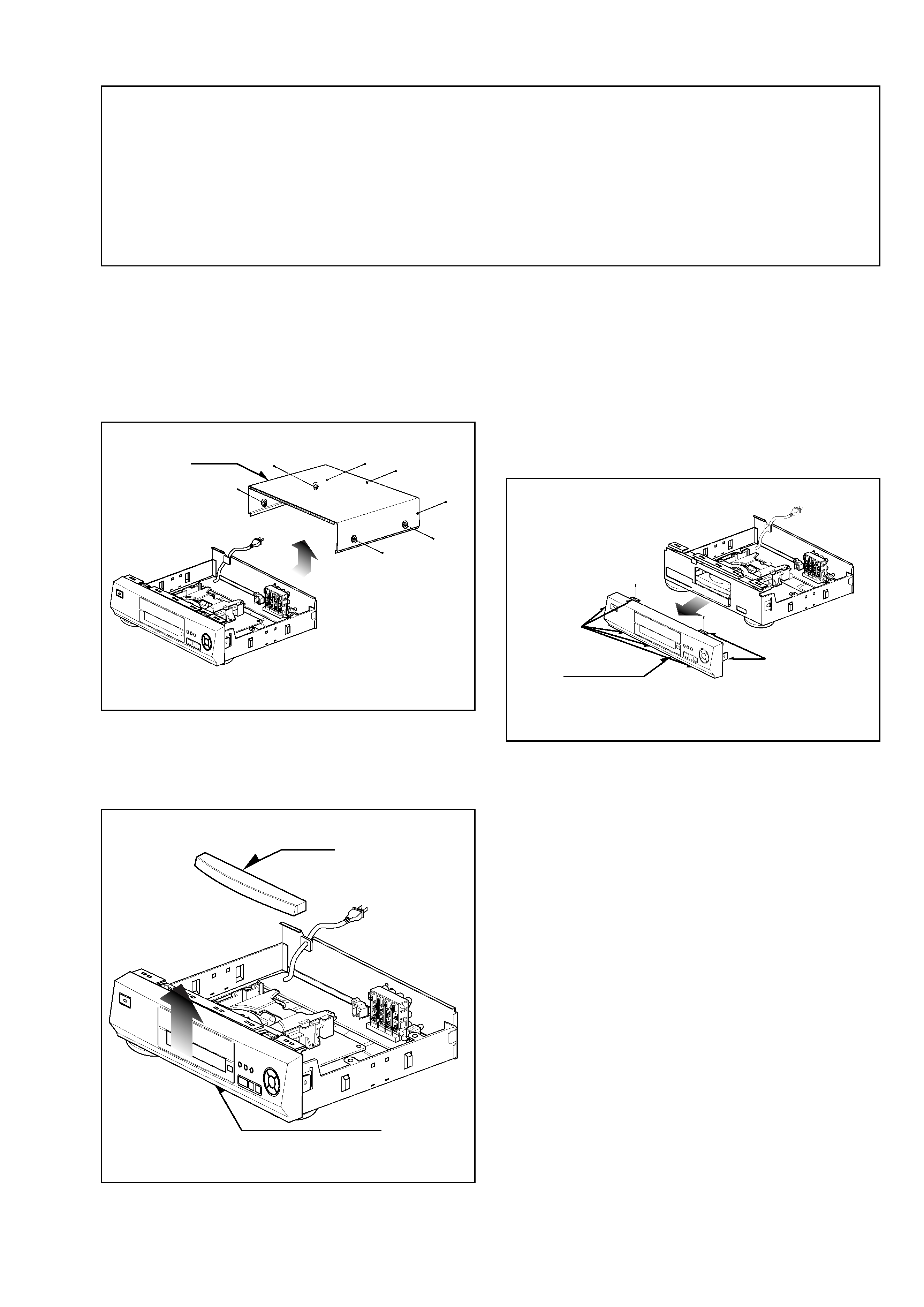
CABINET DISASSEMBLY
1. Top Case
1) Release 7 screws (A). (See Fig-1)
2) Lift the top case with holding the back of it, and remove
it in the direction of the arrow.
2. Tray Door
1) Eject the disc tray.
2) Lift up the tray door in the direction of the arrow.
3. Front Panel
1) Eject the disc tray. (See Fig-2)
2) Remove the tray door. (See Fig-2)
3) Release 2 screws (B).
4) Pull the front panel toward you while pressing 7
stoppers to disengage, and remove the front panel. (See
Fig-3)
Tray Door
Disc Tray
Fig-2
Fig-1
Front Panel
Stopper
Stopper
(B)
(B)
(A)
Top Case
(A)
(A)
(A)
(A)
(A)
(A)
Fig-3