SERVICE MANUAL
DA
TA
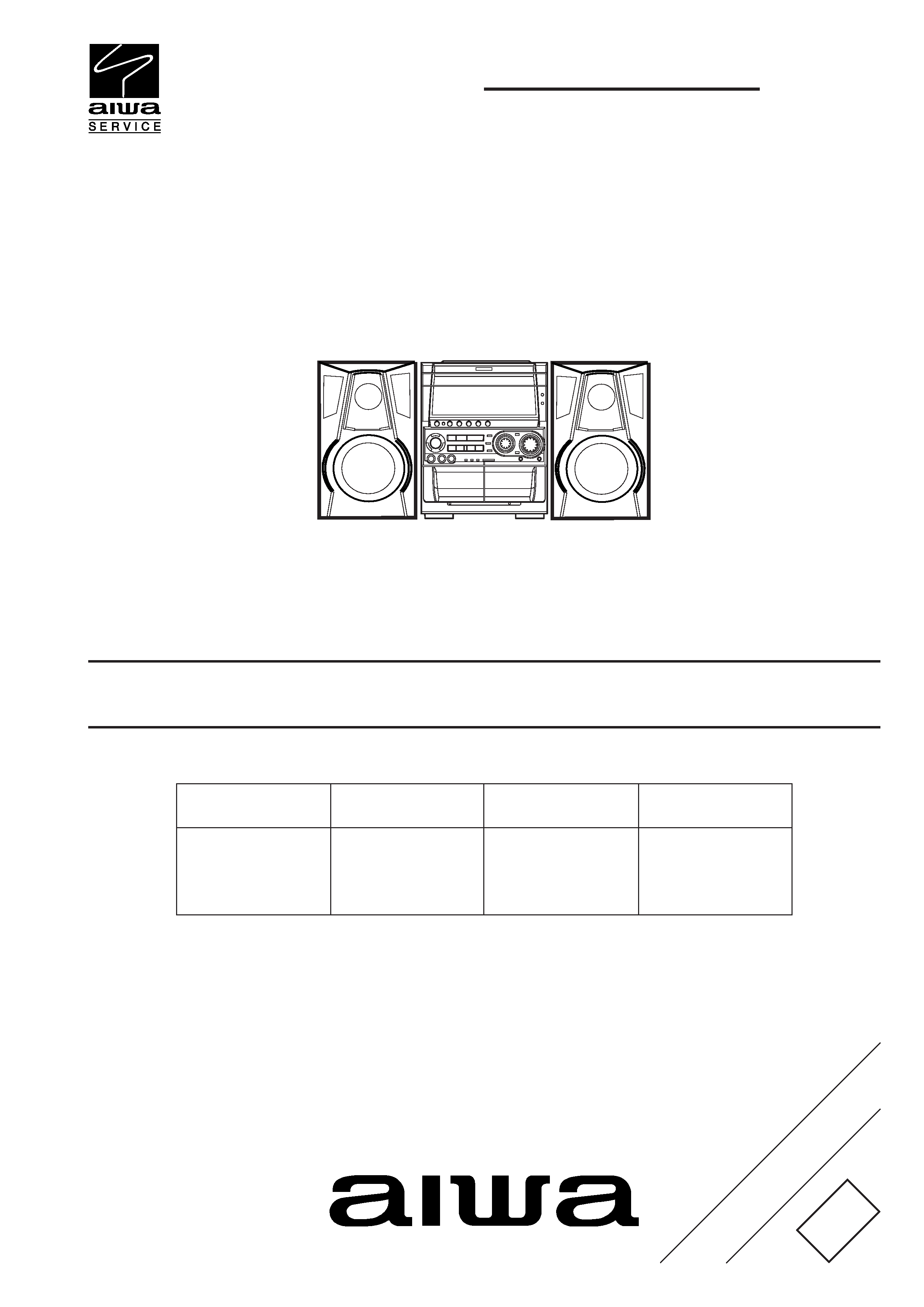
NSXHMT75
SYSTEM
CD
CASSEIVER
REMOTE
CONTROLLER
CXNHMT75
COMPACT DISC/
STEREO CASSETTE RECEIVER
BASIC TAPE MECHANISM : 2ZM-3 MK2 PR4NM
BASIC CD MECHANISM : AZG-1 ZD3RDM
NSX-HMT75 U
S/M Code No. 09-003-425-9R1
REVISION
· This Service Manual is the "Revision Publishing" and replaces "Simple Manual"
(S/M Code No. 09-003-425-9T1).
· If requiring information about the CD mechanism, see Service Manual of AZG-1,
(S/M Code No. 09-001-335-3N8).
SPEAKER
SXNAJ72
SX-R275
SX-C605
RCZAS05
2
SPECIFICATIONS
REF. NO
PART NO.
KANRI
DESCRIPTION
NO.
ACCESSORIES LIST
1
8A-NFU-903-010
IB,U(ESF)M
2
8Z-NFV-702-010
RC UNIT,RC-ZAS05
3
87-006-225-010
ANT,LOOP ANT NC2
4
87-043-115-010
FEEDER-ANT,FM
· Design and specifications are subject to change without notice.
· Dolby noise reduction manufactured under license from Dolby Labo-
ratories Licensing Corporation.
· "DOLBY", and the double-D symbol
are trademarks of Dolby
Laboratories Licensing Corporation.
· The word "BBE" and the "BBE symbol" are trademarks of BBE
Sound, Inc.
· Under license from BBE Sound, Inc.
3
PROTECTION OF EYES FROM LASER BEAM DURING SERVICING
VAROITUS!
Laiteen Käyttäminen muulla kuin tässä käyttöohjeessa mainit-
ulla tavalla saattaa altistaa käyt-täjän turvallisuusluokan 1 ylit-
tävälle näkymättömälle lasersäteilylle.
VARNING!
Om apparaten används på annat sätt än vad som specificeras i
denna bruksanvising, kan användaren utsättas för osynling
laserstrålning, som överskrider gränsen för laserklass 1.
Caution: Invisible laser radiation when
open and interlocks defeated avoid expo-
sure to beam.
Advarsel:Usynling laserståling ved åbning,
når sikkerhedsafbrydere er ude af funktion.
Undgå udsættelse for stråling.
CAUTION
Use of controls or adjustments or performance of procedures
other than those specified herein may result in hazardous
radiation exposure.
ATTENTION
L'utilisation de commandes, réglages ou procédures autres que
ceux spécifiés peut entraîner une dangereuse exposition aux
radiations.
ADVARSEL!
Usynlig laserståling ved åbning, når sikkerhedsafbrydereer ude
af funktion. Undgå udsættelse for stråling.
This Compact Disc player is classified as a CLASS 1 LASER
product.
The CLASS 1 LASER PRODUCT label is located on the rear
exterior.
This set employs laser. Therefore, be sure to follow carefully the
instructions below when servicing.
WARNING!
WHEN SERVICING, DO NOT APPROACH THE LASER EXIT
WITH THE EYE TOO CLOSELY. IN CASE IT IS NECESSARY TO
CONFIRM LASER BEAM EMISSION. BE SURE TO OBSERVE
FROM A DISTANCE OF MORE THAN 30cm FROM THE
SURFACE OF THE OBJECTIVE LENS ON THE OPTICAL
PICK-UP BLOCK.
CLASS 1
KLASSE 1
LUOKAN 1
KLASS 1
LASER PRODUCT
LASER PRODUKT
LASER LAITE
LASER APPARAT
Precaution to replace Optical block
(KSS-213F)
1) After the connection, remove solder shown in
the right figure.
Body or clothes electrostatic potential could ruin
laser diode in the optical block. Be sure ground
body and workbench, and use care the clothes
do not touch the diode.
4
NOTE ON BEFORE STARTING REPAIR
Charging voltage (V)
Discharging
Rated power (W)
Parts number
(C101, 102)
resistor (
)
25-48
100
3
87-A00-247-090
49-140
220
5
87-A00-232-090
Note: The reference numbers (C101, C102) of the electrolytic capacitors can change depending on the models. Be sure to check the
reference numbers of the charging capacitors on schematic diagram before starting the discharging work.
2. Check items before exchanging the MICROCOMPUTER
Be sure to check the following items before exchanging the MICROCOMPUTER. Exchange the MICROCOMPUTER after confirming
that the MICROCOMPUTER is surely defective.
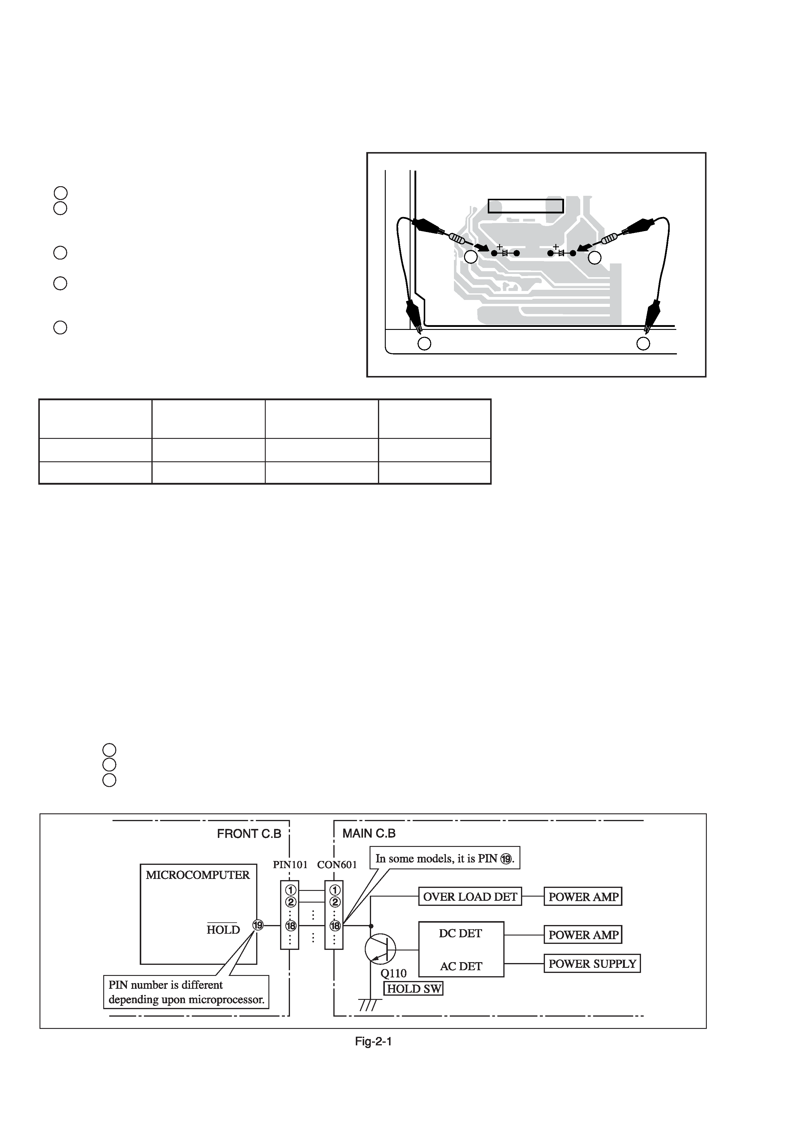
2-1. Regarding the HOLD terminal of the MICROCOMPUTER
When the HOLD terminal (INPUT) of the MICROCOMPUTER is "H", the MICROCOMPUTER is judged to be operating correctly.
When this terminal is "L", the main power cannot be turned on. Therefore, be sure to check the terminal voltage of the HOLD
terminal before exchange.
When the MICROCOMPUTER is not defective, the HOLD terminal can also go "L" when the POWER AMPLIFIER has any
abnormalities that triggers the abnormality detection circuit on the MAIN C. B. that sets the HOLD terminal to "L".
· Good or no good judgement of the MICROCOMPUTER
1
Turn on the AC main power.
2
Confirm that the main power is turned on and the HOLD terminal of the MICROCOMPUTER keeps the "H" level or not.
3
When the HOLD terminal is "L" level, the abnormality detection circuit is judged to be working correctly and the
MICROCOMPUTER is judged to be good.
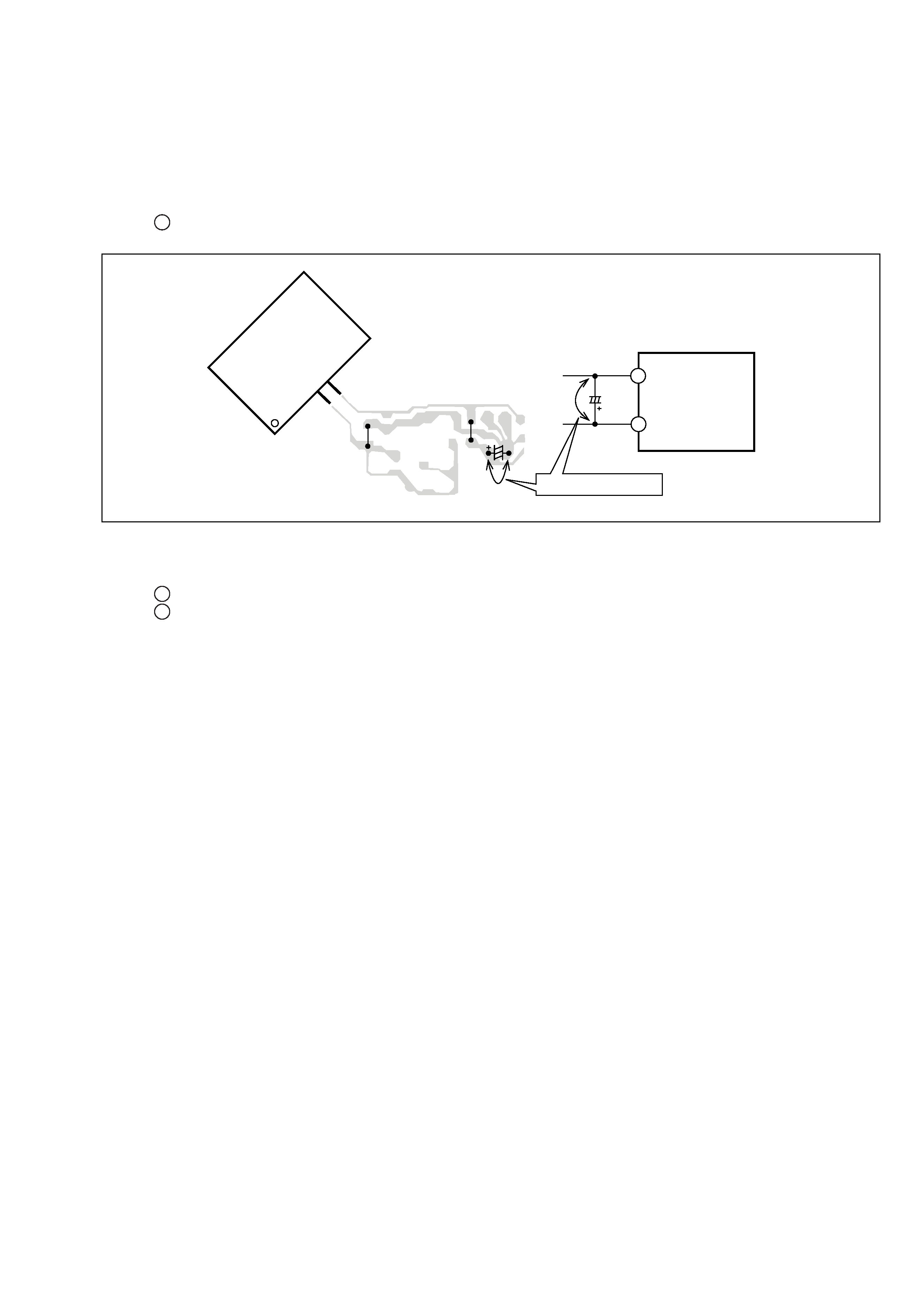
1. Forced discharge of electrolytic capacitor of power supply block
When repair is going to be attempted in the set that uses relay circuit in the power supply block, electric potential is kept charged across
the electrolytic capacitors (C101, 102) even though AC power cord is removed. If repair is attempted in this condition, secondary defect
can occur.
In order to prevent the secondary trouble, perform the following measures before starting repair work.
Discharge procedure
1
Remove the AC power cord.
2
Connect a discharging resistor at an end of lead wire that
has clips at both ends. Connect the other end of the lead
wire to metal chassis.
3
Contact the other end of the discharging resistor to the
positive (+) side (+VH) of C101. (For two seconds)
4
Contact the same end of the discharging resistor as step 3
to the negative (-) side (-VH) of C102 in the same way.
(For two seconds)
5
Check that voltage across C101 and C102 has decreased
to 1 V or less using a multimeter or an oscilloscope.
Select a discharging resistor referring to the following table.
MAIN C.B
D101
C101
C102
3
4
22
5
In such a case, check also if the POWER AMPLIFIER circuit or power supply circuit has any abnormalities or not.
2-2. Regarding reset
There are cases that the machine does not work correctly because the MICROCOMPUTER is not reset even though the AC power
cord is re-inserted, or the software reset (pressing the STOP key + POWER key) is performed.
When the above described phenomenon occurs, it can lead to wrong judgement as if the MICROCOMPUTER is defective and to
exchange the MICROCOMPUTER. In such a case, perform the forced-reset by the following procedure and check good or no
good of the MICROCOMPUTER.
1 Remove the AC power cord.
2
Short both ends of the electrolytic capacitor C113 that is connected to VDD of the MICROCOMPUTER with tweezers.
3
Connect the AC power cord again. If the MICROCOMPUTER returns to the normal operation, the MICROCOMPUTER is
good.
Note: The reference number or MICROCOMPUTER pin number of transistor (Q110) and electrolytic capacitor (C113) can change depending
on the models. Be sure to check the reference numbers on schematic diagram before starting the discharging work.
2-3. Confirmation of soldering state of MICROCOMPUTER
Check the soldering state of the MICROCOMPUTER in addition to the above described procedures. Be sure to exchange the
MICROCOMPUTER after surely confirming that the trouble is not caused by poor soldering but the MICROCOMPUTER itself.
Fig-2-2
MICRO-
COMPUTER
MICR
OCOMPUTER
FRONT C.B
FRONT C.B
VSS
VDD
C113
18
15
C113
18
15
Short with tweezers.