SERVICE MANUAL
DA
TA
MD / CD
STEREO SYSTEM
BASIC TAPE MECHANISM : TN-21ZSC-2003
BASIC CD MECHANISM : DA11T3C
BASIC MD MECHANISM : AZG-4 A
LCX-MD211 EZ
S/M Code No. 09-00B-429-4S2
SUPPLEMENT
· This Service Manual contains the additional information "TEST MODE",
"ADJUSTMENT", "IC BLOCK DIAGRAM", "IC DESCRIPTION",
"LCD DISPLAY" and "VOLTAGE" for the model LCX-MD211(EZ).
If requiring the other information, see Service Manual of LCX-MD211(EZ),
(S/M code No.09-007-429-4R2).
LCXMD211
SYSTEM
SPEAKER
SX-MD210
REMOTE
CONTROLLER
RC-AAT11
2
TEST MODE
1-1 How to activate CD Test Mode
Insert the AC plug while pressing the "CD function" button.
Test mode will be activated and [CD TEST] will be appeared in the LCD display.
Note: Test mode can not be activated when CD door switch is opened.
1-2 CD Test Mode Functions
CD TEST MODE
* Note 1: There are cases when CD cannot be operated owing to the protection circuit being operated when heat builds up in the driver IC if the
focus search is operated continually for more than 10 minutes. In this case, the power supply should be switched off for ten minutes
until heat has been reduced and then re-start.
1-3 How to cancel CD Test Mode
Either one of the following operations will cancel the CD test mode.
· Open the CD door switch.
· Press "POWER" button.
· Disconnect the AC plug.
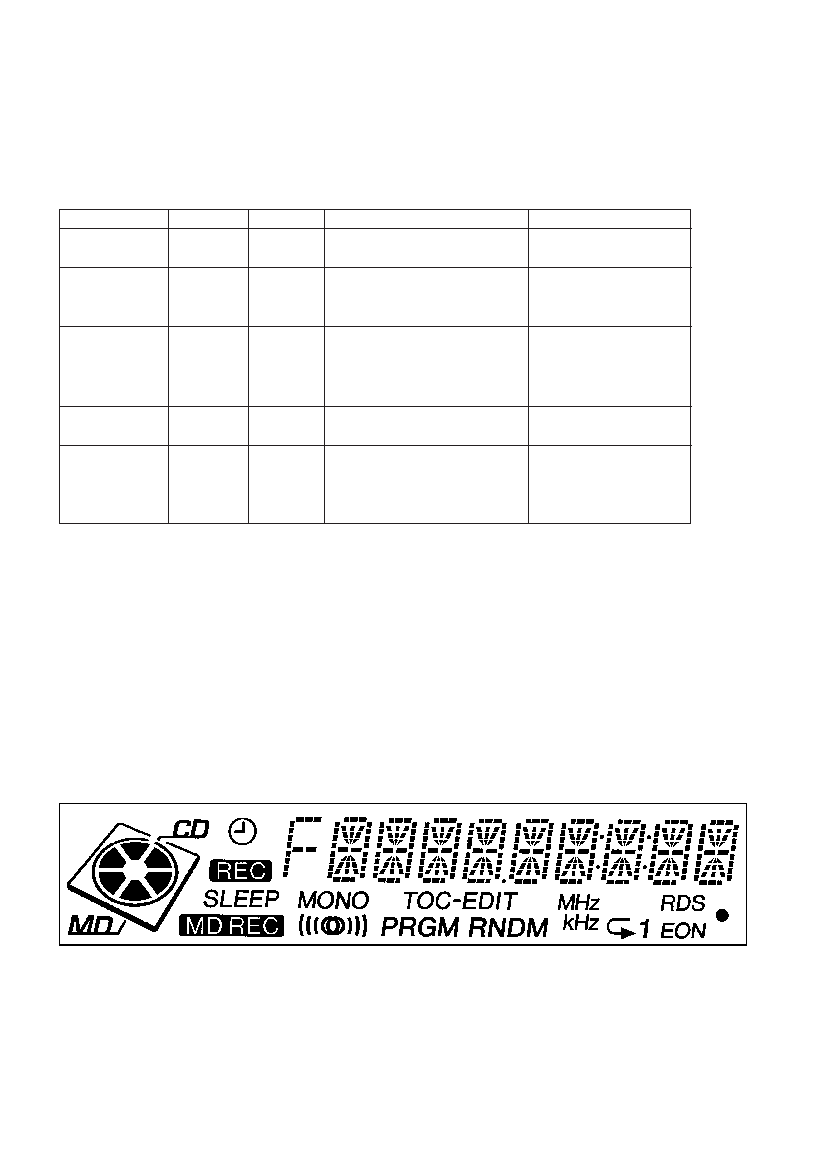
LCD TEST MODE
1-1 How to activate LCD Test Mode
Insert the AC plug while pressing the "DISPLAY" button.
LCD display is fully illuminated and then all segments are lit on and off every one second.
1-2 How to cancel LCD Test Mode
LCD test mode will cancel by press "POWER" button or disconnect the plug.
Start Mode
Display
Search Mode
Continuous Focus Search (Pickup lens
repeat full swing)
* Note 1
Activate CD
Test Mode
CD TEST
Function
Mode
Operation
Content
SEARCH
Play Mode
PLAY
· Normal Playback
· When TOC READ is unavailable,
continuous Focus Search (Same as
Search Mode Operation)
· Focus servo
· Tracking servo
· CLV servo
· Sled servo
Traverse Mode
TRAVERS
Tuner Function
Button
Playback pause status
Tracking servo OFF
Sled Mode
SLED IN
SLED OUT
· Shift to the internal circumference of
pickup
· Shft to the external circumference of
pickup
· Sled servo
· Mecha operation check
s
E
g
f
· APC circuit check
· Laser current measurement
· Focus error waveform check
3
MD TEST MODE
1-1 How to start up MD Test Mode
Insert the AC plug while pressing the "MD function" button.
After the MD test mode has started up, [MD TEST] message appears and the test mode becomes operatable.
Note: · Disconnect the AC plug immediately if any mechanism abnormalities.
· Playback and recording are not possible during the test mode.
1-2 How to cancel MD Test Mode
1) Press the "MD EJECT" button and remove the disc.
2) Disconnect the AC plug or press "POWER" button.
1-3 Operation Check Mode
1) Checks after the test mode has started up.
The following playback audio circuits can be checked.
· Enable circuit to check ------------ DAC, LINEAMP, HEADPHONE AMP
· Output level ------------------------- 1KHz, -24dB
2) Switch status check
ON/OFF statuses of main unit and mechanism switches can be checked on display.
1-4 How to switch to Servo Standby Mode
When the test mode has been established, the mode changes to the servo standby mode by pressing "s" button (lndication on display : ALL
SVOFF).
The various check modes can be entered from this mode.
Pressing the "s" button during each operation returns to [ALL SVOFF].
1-5 Checking Sled Operation
1) When "g" button is pressed in the [ALL SVOFF] state, pickup moves in the outer direction. [T SLEDFWD] is displayed.
2) When "g" button is pressed in the [ALL SVOFF] state, pickup moves in the inner direction. [T SLEDRVS] is displayed.
1-6 Checking Laser Power
1) The laser power is switched each time the "EDIT" button is pressed in the "ALL SVOFF" state. Laser power output is changed as
OFFbLASER READbLASER 1/2bLASER WRITEbOFF order and indication on the display is follows;
OFF
Indication on display
LASER 1/2 WRITE
Mode
LASER READ
LASER WRITE
ALL SVOFF
LA READ
LA 1/2
LA WRITE
2) Press "s" button to return the display to [ALL SVOFF] after checking.
1-7 Checking OWH (Over Write Head) Operation
The operation of OWH can be checked by pressing following buttons in the loading status.
"MD EJECT" button-----------------------OWH UP
"SYNCHRO REC" button----------------OWH DOWN
* Note: Do not down OWH when using the high reflection disc (CD).
1-8 Checking Servo Operation
· Checking the focus search and spindle kick 1
1) When "E" button is pressed in the [ALL SVOFF] state without disc, focus search and spindle kick are executed continuously.
[
FOCUS SCH] is displayed.
REC PROTECT
Switch state
REFRECT
When the high reflection disc (CD) is
used.
TOC EDIT
Switch name
Indication on Display
Usalde disc
MD REC
INNER
MONO
Playback only disc
When the write-protection tab of disc is
stopped.
When the pickup is the positioned at the
innermost track (when the LIMIT SW is
ON).
Record/playback disc

4
2) Press "s" button to display [ALL SVOFF] after checking
· Checking the focus search and spendle kick 2
1) When "TUNER function" button is pressed in the "ALL SVOFF" state regardless disc existence, focus search and spindle kick are executed
continuously. [FOCUS CHK] is displayed and S curve can be checked if disc is loaded.
2) Press "s" button to display [ALL SVOFF] after checking.
· Checking Focus Servo
1) Insert a test disc.
2) Move pickup to center track by pressing "g" or "f" buttons.
3) Press "JOG MODE" button to set the servo mode according to the inserted disc as follows;
· MO disc (MO)----------------Indication on display [SEL GRV].
· PIT disc (CD)-----------------Indication on display [SEL PIT].
4) Press "E" button.
If focus servo is operating normally, the messge [FOCUS ON] is displayed after [FOCUS SCH].
5) Press "s" button to display [ALL SVOFF] after checking.
· Checking all Servos are turned on.
1) Tracking and sled servos and turned on and all servos work when "ENTER" button is pressed in the [FOCUS ON!] state. [ALL SV ON] is
displayed if all servos are normal.
2) Press "s" button to display [ALL SVOFF] after checking.
5
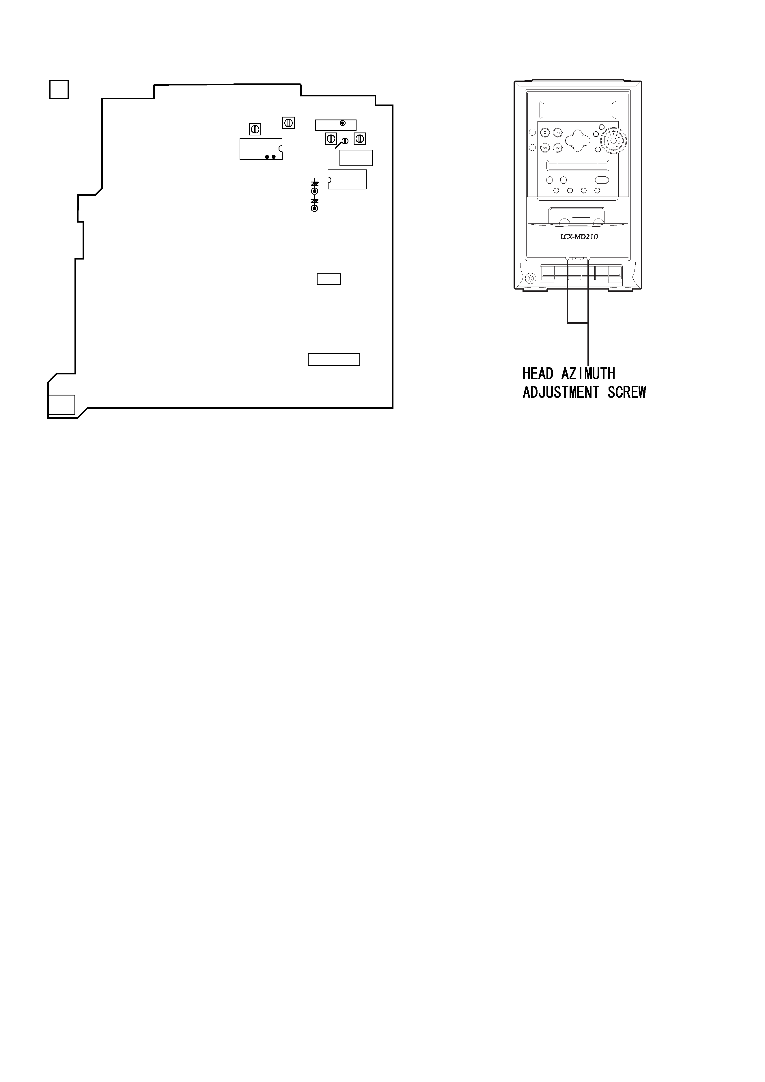
ADJUSTMENT <TUNER / DECK>
TP4 (VT)
FFE801
L981
1
4
IC721
+
+
TP7(Rch)
C786
TP8(Lch)
C785
TP6
TP5
28
26
IC771
L772
L771
IC201
IC202
J201
MAIN C.B
A
L941
L942
TC942
< TUNER SECTION >
1. MW VT Check
Settings :
· Test point : TP4 (VT)
Method :
Set to MW 1602kHz and check that the test point is
less than 5.6V.
2. MW Tracking Adjustment
Settings :
· Test point : TP7 (RCH), TP8 (LCH)
· Adjustment location : L981
Method :
Set to MW 999kHz and adjust L981so that the test
point becomes maximum.
3. AM IF Adjustment
Settings :
· Test point : TP7 (RCH), TP8 (LCH)
· Adjustment location:
L772 .................................................... 450kHz
4. LW VT Adjustment
Settings :
· Test point : TP4 (VT)
· Adjustment location : L942
Method :
Set to LW 153kHz and adjust L942 so that the test
point becomes 1.3V
± 0.05V.
5. LW Tracking Adjustment
Settings :
· Test point : TP7 (RCH), TP8 (LCH)
· Adjustment location :
L941 .................................................... 153kHz
TC942 .................................................. 285kHz
Method :
Set up TC942 to center before adjustment. The level at
153kHz is adjusted to maxinum by L941. Then the
level at 285kHz is adjusted to maxinum by TC942.
6. FM VT Check
Settings :
· Test point : TP4 (VT)
Method :
Set to FM 108MHz and check that the test point is less
than 8.2V .Then set to FM 87.5MHz and check that
the test poit is more than 1.5V.
7. FM Tracking Check
Settings :
· Test point : TP7 (RCH), TP8 (LCH)
Method :
Set to FM 98MHz and check that the test point is less
than 18dB.
8. DC Balance / Mono Distortion Adjustment
Settings : · Test point : TP5, TP6 (DC balance)
TP7 (RCH), TP8(LCH)(Distortion)
· Adjustment location : L771
· Input level : 54dB
Method :
Set to FM 98MHz and adjust L771 so that the voltage
between TP3 and TP4 becomes 0V
± 0.04V.
Next, check that the distortion is less than 1.5%.
9. FM Separation Check
Settings :
· Test point : PHONE JACK (J201)
· Input level : 54dB
Method :
Set to FM 98MHz and check that the test point is more
than 20dB.
< DECK SECTION >
10. Head Azimuth Adjustment
Settings :
· Test tape : TTA330
· Test point : PHONE JACK (J201)
· Adjustment location : Head azimuth
adjustment screw
Method :
1) Connect the L positive terminal to CH1 probe
(positive side) of oscilloscope and L negative
terminal to CH1 probe (negative side).
Connect the R positive and negative terminals to
CH2 probe same condition as CH1 probe.
2) Play back the 10kHz signal of the test tape.
3) Adjust the head azimuth adjustment screw to
become maximum waveform in the oscilloscope
and same phase for CH1 and CH2.